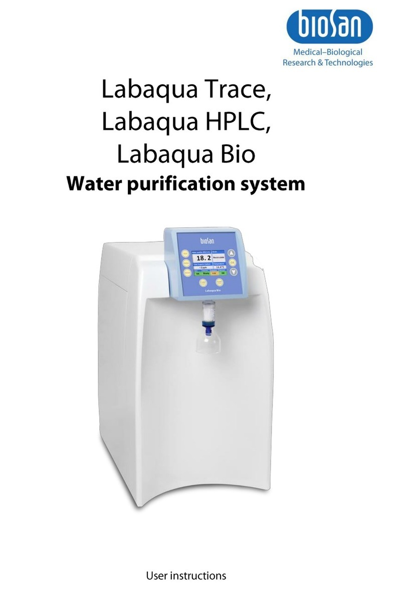
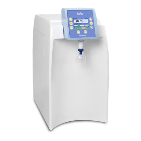
Biosan Labaqua User manual


2

3
Contents
1. Safety precautions ...................................................................................................4
2. General information..................................................................................................5
3. Getting started..........................................................................................................8
4. Rinsing the system.................................................................................................11
5. Operation ...............................................................................................................12
6. TOC level reduction and monitoring.......................................................................14
7. Specifications.........................................................................................................15
8. Cleaning and maintenance.....................................................................................17
9. Warranty and Claims..............................................................................................18
10. Declaration of Conformity.......................................................................................19

4
1. Safety precautions
The following symbol means:
Caution! Make sure you have fully read and understood the present Manual
before using the equipment. Please pay special attention to sections
marked by this symbol.
Caution! Do not service the unit while the open UV lamp is switched ON.
Otherwise it can expose the operator to a dangerous level of UV
emission.
GENERAL SAFETY
Use only as specified in the operating manual provided.
The unit should not be used if dropped or damaged.
The unit must be stored and transported in a horizontal position (see package
label).
After transportation or storage, keep the unit at room temperature for 2-3 hrs before
connecting it to the electric circuit.
Use only cleaning and decontamination methods recommended by the
manufacturer.
Use only original accessories (fuses, tubes, etc.) provided by the manufacturer and
ordered specifically for this model.
Do not make modifications to the design of the unit.
Do not block any ventilation openings.
Do not operate the unit with its covers removed.
Do not drink deionized water.
WATER LEAKAGE SAFETY
Make sure that all water connection tubes are unbent, kink-free.
Make sure that all water connectors are tight.
When installing the tank, connect the fitting marked „Overflow” to the drain. Make
sure that the drain level is lower than the „Overflow” fitting level. This will prevent
water leakage in case of tank level sensor failure.
Do not operate the tank pump if there is no water in the tank. Tank pump may fail if
it is run dry.
A 5 μm sediment filter has to be installed in the feed water supply line. Failure to
install the filter may result in clogging of strainer inside the system and water flow
blockage.
Shut off tap water supply when leaving the system unattended.
ELECTRICAL SAFETY
A power line regulator may be required in the areas where the supplied power is
subject to voltage fluctuations exceeding 10% of the nominal.
Connect only to a mains outlet with voltage corresponding to that on the serial
number label.
Verify that the fuses are properly installed.

5
Do not plug the unit into an ungrounded mains outlet, and do not use an
ungrounded extension lead.
Ensure that the power switch and power connector are easily accessible during
use.
Disconnect the unit from the electric circuit before moving or performing servicing
tasks.
Turn off the unit by disconnecting the mains plug from mains outlet.
If liquid penetrates into the unit, disconnect it from the external power supply unit
and have it checked by a repair and maintenance technician.
Do not operate the unit in premises where condensation can form. Operating
conditions of the unit are defined in the Specifications section.
DURING OPERATION
Do not operate the unit in environments with aggressive or explosive chemical
mixtures. Please contact manufacturer for possibility of operation of the unit in
specific atmosphere.
Do not operate the unit if it is faulty or has been installed incorrectly.
Do not use outside laboratory rooms.
BIOLOGICAL SAFETY
It is the user’s responsibility to carry out appropriate decontamination if hazardous
material is split on or penetrates into the equipment.
2. General information
Water purification system “Labaqua” produces pure and ultrapure water that
complies with ISO 3696 Grade II and Grade I water requirements respectively.
Pure (ISO 3696 Grade II) water applications include, but are not limited to:
Feed for laboratory equipment (washing machines, clinical analysers, humidifiers,
autoclaves, hydrogen gas generators);
Manufacturing of chemical and biochemical reagents;
Buffer preparation;
Microbiological media preparation;
Sensitive analytical techniques (e.g. atomic absorption, ICP-OES).
Ultrapure (ISO 3696 Grade I) water applications include, but are not limited to:
High sensitivity analytical techniques (ICP-MS);
High performance liquid chromatography;
Molecular biology;
Cell culture.

6
There are two types of Labaqua water purification systems:
Labaqua HPLC –Ultrapure water system for analytical applications. Includes 25 l
water storage tank. Uses tap water as feed water, often referred to
as “tap water system”.
Labaqua Bio –Ultrapure water system for molecular biology and cell culture
applications. Includes 25 l water storage tank. Uses tap water as
feed water, often referred to as “tap water system”.
Principle of operation
The hydraulic diagram of Labaqua water purification system is shown below.
The solenoid valve (Fig. 1/1) controls intake of feed water from the tap. The first
purification stage consists of the pre-filter set (P/N 10019, fig. 1/2 and 1/3) that includes
sediment filter and activated carbon intended to remove particles, free chlorine, organics
and colloids. A pressure switch (Fig. 1/5) controls feed water pressure. If feed water
pressure falls below 0.7 bar, the system will automatically switch on the boost pump (Fig.
1/4) and “LowPres” message will be shown on the display.
The boost pump (Fig. 1/4) is used to maintain pressure at the level necessary for
the efficient operation of the reverse osmosis membrane (only in the tap water systems,
Fig. 1/9), deionization module (P/N 10310, fig. 1/12), and UV sterilization module (if
installed, P/N 10102, fig. 1/16).
From the boost pump, the feed flow goes to the membrane to be split into two parts:
the permeate, diffused through the membrane, and the concentrate, which passes over the
membrane, carrying away contaminants to the drain. The permeate goes to the third
purification step –the IonPro deionization module (P/N 10310, fig. 1/12) where the
remaining ions are removed.
Before entering the tank, water is sterilized by UV lamp (if installed, P/N 10102, fig.
1/16); water quality is controlled by Grade 2 water conductivity sensor (Fig. 1/11). LCD
display provides information about the system status.
Purified water is stored in the tank and recirculated on periodical basis. Water in the
tank meets requirements of ISO 3696 Grade II.
Fig. 1. Principle of operation

7
Water dispensing
To dispense ISO 3696 Grade I water, press the Pump Grade I key. The pump (Fig.
1/15) is switched on and water flows through photooxidation module (P/N 10105, fig. 1/16),
polishing cartridge (P/N 10030, fig. 1/17) and protective sediment filter (Fig. 1/18). After
several seconds the valve (Fig. 1/21) opens and Grade I water is dispensed via the 0.22
μm point-of-use microfilter. Labaqua Bio system has an ultrafilter instead of the microfilter.
To dispense ISO 3696 Grade II water, press the Pump Grade II key. Grade II
dispense pump is switched on, and water is dispensed via the “Out” port of the tank.
Possible Labaqua modifications
Labaqua HPLC: Ultrapure, equipped with photooxidation module for low TOC.
Labaqua Bio: Ultrapure, equipped with UV sterilization module, ultrafilter and photooxidation
module for low TOC.

8
3. Getting started
3.1. Unpacking.
Remove packing materials carefully and retain for them future shipment or storage
of the unit. Examine the unit carefully for any damage incurred during transit. The
warranty does not cover in-transit damage.
Caution! Due to the unit’s weight its unpacking and installing is to be carried
out by two persons.
3.2. Complete set. Package contents:
Standart set:
- Labaqua Bio / Labaqua HPLC unit....................................................................1 pce
- LLDPE tube, Ø1/4”, 3m.....................................................................................5 pcs
- point-of-use ultrafilter set (Bio) / microfilter set (HPLC)......................................1 set
- power cable.......................................................................................................1 pce
- prefilter cartridge ...............................................................................................2 pcs
- IonPro deionization cartridge.............................................................................1 pce
- polishing cartridge.............................................................................................1 pce
- controller module...............................................................................................1 pce
- Ø1/4” elbow.......................................................................................................5 pcs
- Ø1/2” NPTF tap water to Ø1/4” JG elbow adapter............................................1 pce
- Ø3/4” NPTF tap water to Ø1/4” JG elbow adapter............................................1 pce
- Ø1/2”NPT tap water to Ø1/4” JG adapter.........................................................1 pce
- Ø1/4” bypass tube with elbows .........................................................................2 pce
- Ø1/4” elbow with tube........................................................................................4 pce
- external storage tank, with pump, level switch and tap......................................1 set
- Ø3/8”with elbow, 3m overflow tube..................................................................1 pce
- Ø3/8”, 1m tank dispense tube...........................................................................1 pce
- tank cable..........................................................................................................1 pce
- hex key for controller module............................................................................1 pce
- Operation manual, declaration of conformity...................................................1 copy
Optional accessories:
- TOC monitoring module (integrated).........................................................on request
- 0.22 μm air vent filter for the storage tank ................................................on request
- Reverse osmosis membrane for higher capacity (20 L/h) ........................on request
- Electrodeionization module 10-30 L/h ......................................................on request
- Water storage tank “Comfort”
with level switch and dispense pump, 60 L ..............................................on request
- Water storage tank “Economy”
with level switch and dispense pump, 50 L ..............................................on request
- Water storage tank “Comfort” with dispense pump, 100 L .......................on request
- Water storage tank “Comfort” with dispense pump, 200 L .......................on request
- Water storage tank “Comfort” with dispense pump, 300 L .......................on request
- IQ/OQ documentation ..............................................................................on request
- For clean tap water with hardness < 130 ppm:
Pre-filter housing 10” with fittings .............................................................on request
Sediment filter 1 μm .................................................................................on request
- For muddy and/or hard tap water with hardness > 130 ppm:
Pre-filter set 3 x 10” with cartridges (polyphosphate, 5 and 1 μm) ...........on request

9
3.3. Pre-installation requirements
The Labaqua system can be placed on a bench or attached to a wall. If the system
is placed on the bench, allow space on the bench 500x500mm. Allow enough space
for the tank (DMH 400x400x600mm) under the bench.
Electrical connections: 230 V, 3A.
Feed water should be filtered with 5 μm sediment filter (not included).
Feed water should be filtered with at least one 5 μm sediment filter. If the filter is
not installed, the input strainer may become clogged thus blocking the water
flow, or pre-filter life can be reduced.
Sediment filter for tap water line is usually available from a local plumbing shop. If
necessary, the sediment filter set (that consists of 5 um sediment filter and 1 um
sediment filter) can be obtained (example below). The part number is 10168.
Attention! In case of Labaqua system pre-filter set (P/N 10019) pre-mature
clogging, we ship the new pre-filter under warranty only if we get a
photo of the sediment filter installed in the tap water line.
Feed water hardness does not affect produced water quality. However, operation of
the system with hard fed water may result in premature clogging of reverse osmosis
membranes and reduced Grade 2 water flow. Therefore, it is strongly
recommended to install a water softener or polyphosphate filter if water
hardness is above 160 ppm.
Drain level should be lower than Overflow port of the tank. Drain is required. The
water purification system is equipped with Ø1/4’’ drain pipe. Overflow port pipe is
Ø3/8’’.
Feed water outlet for Labaqua system connection has to be ½’’ or ¾’’ male thread.
A feed water outlet with ½’’ female thread is acceptable although not
recommended. The system is equipped with feed water tube (1/4’’ OD) and
adapters for ½’’ threaded outlets (male and female thread) as well as for ¾’’
threaded outlet (male thread). The feed water tube should be connected to the ¼’’
JohnGuest fitting of the adapter. Feed water outlet should be equipped with a valve
for shutting off water supply.

10
3.4. Setting up
3.4.1. Install the controller module and connect the cable (Fig. 2/1).
3.4.2. Carefully attach the controller module to the holder at the top right of the system
(Fig. 2/2)
3.4.3. While the system is disconnected from mains, it is recommended to carefully
remove the rear panel and check for any transportation damage. Reinstall the panel
before connecting the power cable to 230V AC power supply socket.
3.4.4. Fix the controller module with two screws on the lower side of the module.
3.4.5. Unpack the microfilter/ultrafilter and screw it into the threaded outlet under the
controller module holder (Fig. 2/3). Before connecting, make sure that the sealing
O-ring is inside the holder.
3.4.6. Connect the feed water to the Ø1/4’’ John Guest inlet marked Tap Water. Use an
appropriate adapter from tap water to Ø1/4’’ tube, see p. 3.2. Tap water should be
filtered with 5-micron mechanical filter (not included).
3.4.7. Connect Ø1/4’’ JG connector marked Drain to the drain using Ø1/4’’ plastic tube.
Note: Unscrew the cap of the purified water storage tank and remove the
packing material inside.
3.4.8. Connect Ø1/4’’ John Guest outlet “OUT”to the inlet “In”of the tank.
3.4.9. Connect Ø1/4’’ John Guest outlet “Rec Out”to the inlet “Rec In”of the tank.
3.4.10.Connect Ø1/4’’ John Guest outlet “Rec In”to the inlet “Rec Out”of the tank.
3.4.11.Connect the tank cable to the TANK connector.
Note: If nothing is connected to the TANK connector, the system will show
“TnkFull”.
3.4.12.Connect the power cable. Make sure the system is properly grounded.
3.4.13.Connect approximately 1 m of Ø3/8’’ tube to the tank Out connector to ensure
convenient Grade II water dispensing. The end of the tube should be free and must
not be connected to anything. The backpressure will damage the pump.
3.4.14.Connect the Overflow connector of the tank to the drain with Ø3/8’’ tube.
Fig. 2. Setting up
3.5. Feed water and drain requirements
3.5.1. Feed water should be filtered with 5 μm sediment filter. If the filter is not installed,
the input strainer may become clogged and block the water flow. Life of pre-filters
can be reduced too.
3.5.2. Feed water connector port can be Ø1/2’’ (male or female) or Ø3/4’’ NPTF (male)
thread. The system is equipped with adapters for both water supply connectors.
The feed water tube should be connected to the Ø1/4’’ JG port of the adapter.

11
3.5.3. Tap water pressure should be above 0.7 bar.
3.5.4. Drain pipe should be lower that the level of the instrument and the level of the
Overflow connector of the tank. The water purification system has Ø1/4’’ OD drain
pipe. The Overflow connector of the tank is for Ø3/8’’ OD pipe.
3.5.5. Feed water supply connector and drain should be within 3 meters from the
installation site.
3.6. Deionization and Polishing module installation.
3.6.1. Push the stems in the ¼’’ elbows with ¼’’ tubes into the John Guest fittings of the
Deionization and Polishing modules.
3.6.2. Install the deionization and polishing modules. The positions of the modules are
marked with labels “IonPro deionization module” and “Polishing module”. Each
module has now John Guest elbows and short tubes installed. Open the front door.
Place a module at the labelled site; push the tubes into John Guest fittings at the
inner wall. Then attach the module fully to the inner wall by putting the latch at the
bottom of the module into slot on the wall.
3.6.3. Screw the pre-filters into the grey filter heads.
4. Rinsing the system
Note: The pre-filter should be rinsed prior operation and each time new
filter is installed. Failure to do so can lead to reduced life of the
reverse osmosis membrane.
Rinse the system according to the following procedure:
4.1. Open the front door. Disconnect the pre-filter outlet tube (right behind the prefilter
heads) from the John Guest fitting (see pictures below). Put a beaker under the
tube.
4.2. Switch on the unit. The display is switched on and “STANDBY” message is shown.
4.3. Open the tap water supply.
4.4. Press and hold the Run key (Fig. 4/8) for 2 seconds and collect approximately 1
litre of water and press the Run key to stop the water flow. The pre-filter is rinsed.
Note: If “TnkFull” message is shown then probably the tank plug is not
connected.

12
4.5. Reconnect the outlet tube to the outlet John Guest elbow.
4.6. Press Run key and wait until storage tank is filled with water.
4.7. Put the end of 3/8’’ tank “Out” tube into a sink, press “Pump Grade 2” and dispense
water from the tank.
4.8. Let the system fill the tank again. As the tank is full, ask the customer to leave the
system overnight (shut off tap water supply for safety reasons). The system will
recirculate water in the tank and get rid of organic compounds as well as rinse the
polishing module.
4.9. The microfilter (or ultrafilter) should be rinsed prior to use! Ask the customer to
press “Pump Grade 1” next morning and dispense water in the tank through point-
of-use filter (microfilter on Labaqua HPLC or ultrafilter on Labaqua Bio). The
microfilter (or ultrafilter) needs to be rinsed with at least 20 litres of purified water.
Fig. 3. Deionization and polishing module sites. The grey fittings above are used for
connecting the modules.
5. Operation
5.1. Switch on the system with the power switch. The display (Fig. 4/1) lights up after
few seconds.
5.2. The display shows information in several rows:
- system messages and current status;
- error messages, if present;
Status messages
Description
Standby
Labaqua is switched off and does not produce water to the
tank.
LowPres
Input pressure is too low.
TnkFull
The storage tank is full.
Disp.
Water is being dispensed.
Recirculate
Water in the storage tank is being recirculated

13
Error messages
Description
Filter
Pre-filter set (P/N 10019) needs replacement
DI Err.
Deionization module (P/N 10310) needs replacement
TankS
Tank sensor is damaged
Beeping sound during
“Running” stage
Sterilization UV bulb needs replacement.
- indication of current water grade (superscript) and water conductivity (precise
readings of water quality are shown when the system is in Running, Grade I
dispense or Recirculation mode);
- water temperature and filter life counter.
5.3. If the system is equipped with TOC (total organic carbon) level monitoring module,
display shows TOC reading (e. g. <2 ppb). TOC level reading will be shown only
after the storage tank is at least partially filled with water and recirculation stage has
started.
5.4. The purified water quality is controlled by two sensors. First sensor (Fig. 1/11)
measures and displays conductivity of Grade II water, flowing into or recirculating in
the storage tank. Second sensor (Fig. 1/19) measures and displays conductivity of
Grade I water that is dispensed at the moment.
5.5. Indication in superscript next to the conductivity can take values “1” or “2”, showing
current water grade.
5.6. To fill the tank with purified water, press and hold the Run key (Fig. 4/8) for 2
seconds. If tank is neither full nor disconnected and the feed water pressure is
enough, the display shows “Running”. Now the Labaqua system is filling the tank
with Grade II water. As soon as the tank is full, the system shuts down the water
supply and shows the “TnkFull” message.
5.7. To dispense Grade I water, press Pump Grade I key (Fig. 4/6). After five to ten
seconds, Grade I water is dispensed through the 0.22 μm filter. If ultrafilter is
installed, loosen the degassing valve to get rid of air. Press the Pump Grade I key
again to stop water dispensing.
5.8. To dispense Grade II water from the tank, press the Pump Grade II key (Fig. 4/7).
To stop dispensing, press the Pump Grade II key again.
5.9. System will circulate water on periodical basis to prevent growth of microorganisms
in the tank. During recirculation phase, the reading of Grade II water is shown on
the display. For the systems with TOC monitoring module, display shows TOC
reading in ppb. TOC reading appears in the left bottom display when purified water
storage tank is full and recirculation stage starts.
5.10. Recirculation is switched off when the system is in the Standby mode. To prolong
life of polishing module, please set the system to the Standby mode if it is not used
for long time (e.g. for the night).
5.11. Press Run key to toggle Standby mode on and off.
5.12. If feed water pressure falls, the display indicates “LowPres”.
Note: To actuate a key, press and hold it for two seconds.

14
Note: If the system is newly installed or has not been used for a long time,
it recommended to leave it in the Recirculating mode for several
hours before usage. It will allow the system to fill the tank and
recirculate water to reduce TOC content.
Fig. 4. Control panel of Labaqua Bio/HPLC
5.13. Navigating the menu. To enter menu, press Menu ESC key (Fig. 4/5). Press ▼ and
▲ keys (Fig. 4/2 and 4/4) to select options, OK key (Fig. 4/3) to confirm and Menu
ESC key to exit.
5.14. Menu consists of two options, “Reset filter counter” that is required to reset filter life
counter when changing filters, and “Options” submenu:
- switch between MΩ*cm and μS/sm conductivity units;
- set recirculation period (time between recirculation cycles);
- set recirculation cycle duration time;
6. TOC level reduction and monitoring
Total organic carbon (TOC) describes level of organic contaminants in pure water.
High concentration of organic contaminants may affect results of several analytical
methods, e.g. high performance liquid chromatography. Therefore, for some applications
TOC level should be controlled and kept minimal.
Grade II water coming to the storage tank generally has low TOC level if proper
deionization resins are used. However, TOC level may rise during storage, therefore water
recirculation through photooxidation module and polishing cartridge is necessary to keep
TOC level low.
Unfortunately, organic contaminants may not have effect on conductivity of water,
so conductivity sensors cannot be used for TOC level monitoring. A special TOC level
monitoring module is needed to measure TOC level. The monitoring module consists of a
TOC photooxidation module, valve and a conductivity sensor.

15
TOC monitoring module (optional) operation principle
During recirculation stage a water sample is introduced into the TOC photooxidation
module where it is oxidized for several minutes. During this phase, water conductivity rises
because of the oxidation of organic molecules. The rise of conductivity is proportional to
TOC level of water.
After the oxidation phase is finished, water is released from the TOC photooxidation
module and its conductivity is measured by the conductivity sensor. TOC level is calculated
from the rise of conductivity.
Note: As TOC level measurement is made during the recirculation stage,
the TOC level value is shown on the display only with storage tank
partially filled with water and during recirculation.
7. Specifications
The unit is designed for operation in cold rooms, incubators and closed laboratory
rooms at ambient temperature from +15°C to +30°C with maximum change at less than
2°C in 24 hours, in a non-condensing atmosphere and relative humidity between 20% and
80%. Biosan is committed to a continuous programme of improvement and reserves the
right to alter design and specifications of the equipment without additional notice.
7.1. Purified water specifications
Grade II water conductivity...................................................................... <0.1 μS/cm
Grade I water resistivity....................................................................... 18.2 MΩ x cm
Grade I water conductivity..................................................................... 0.055 μS/cm
TOC.................................................................................................................<2 ppb
RNase (Labaqua Bio).............................................................................<0.01 ng/mL
DNase (Labaqua Bio)..................................................................................<4 pg/mL
Bacteria.....................................................................................................< 1 cfu/mL
Endotoxins
Labaqua HPLC............................................................................................................................. <0.15 EU/mL
Labaqua Bio............................................................................................................................... < 0.001 EU/mL
Particles larger than 0.22 μm .................................................................... <1 per mL
Nominal flow, Grade II water............................................................................10 L/h
Dispense flow, ultrapure water.......................................................................2 L/min
Dispense flow, pure water..............................................................................4 L/min
Deionization module life (standard module).......................................................1 m3
Recovery......................................................................................................... >30 %

16
7.2. General specifications
Dimensions .................................................................................... 500x400x600mm
Weight*..............................................................................................................30 kg
Storage tank........................................................................................................25 L
Input current / Power consumption......................... AC 200-240 V, 50-60 Hz / 130W
Fuse...........................................................................................................220V, 3 A
Feed water pressure .................................................................................0.5 –5 bar
Feed water conductivity ........................................................................ < 900 μS/cm
Water connections ............................................Ø1/2’’ and Ø3/4’’ NPTF, Ø1/2’’ NPT
Optional accessories
Catalogue number
Integrated TOC monitor
BS-070102-S05
0.22 μm air vent filter for the storage tank
BS-070102-AK
Reverse osmosis membrane for higher capacity (20 L/h)
BS-070102-BK
Electrodeionization module 10-30 L/h
BS-070102-CK
Water storage tank “Comfort” with level switch and dispense pump, 60
L
BS-070102-EK
Water storage tank “Economy” with level switch and dispense pump,
50 L
BS-070102-DK
Water storage tank “Comfort” with dispense pump, 100 L
BS-070102-FK
Water storage tank “Comfort” with dispense pump, 200 L
BS-070102-GK
Water storage tank “Comfort” with dispense pump, 300 L
BS-070102-HK
IQ/OQ documentation
BS-070102-IK
For clean tap water with hardness < 130 ppm:
Pre-filter housing 10” with fittings
BS-070102-JK
Sediment filter 1 μm
BS-070102-KK
For muddy and/or hard tap water with hardness > 130 ppm:
Pre-filter set 3 x 10” with cartridges (polyphosphate, 5 and 1 μm)
BS-070102-LK
Replacement parts
Catalogue number
Pre-filter set
10019
Deionization module
10310
Polishing module
10030
Photo-oxidation module
10105
Photo-oxidation UV bulb
10018
Point-of-use microfilter*
10012
UV sterilization module**
10102
Sterilization UV bulb**
10011
Point-of-use ultrafilter**
10120
* Accurate within ±10%
* In Labaqua HPLC only.
** In Labaqua Bio only.

17
8. Cleaning and maintenance.
8.1. If the unit requires maintenance, disconnect the unit from the mains and contact
Biosan or your local Biosan representative.
8.2. Clean the exterior of the system with soft tissue. Do not use chemicals.
8.3. The water storage tank should be cleaned and disinfected every 2-3 months.
8.4. When the filter counter goes to zero, the pre-filters should be replaced.
- Press the Run key to set the system into the Standby mode.
- Open the front panel and unscrew old pre-filters.
- Rinse and install the new pre-filters (see 4. Rinsing the system).
- Close the front panel.
- Enter menu (see 5.13), select the “Reset filter counter”. Press OK key (Fig. 4/3) two
times to select and confirm.
- Switch off the system.
- Wait 5 seconds and switch on the system again.
8.5. Expendable parts and the replacement interval are shown below:
Description
Replacement interval
Catalogue number
Pre-filter set
When filter life counter goes to zero or
when the filter is clogged (LowPres
appears on the screen even if tap
water pressure is > 1 bar)
10019
Deionization module
When “DI Err” error message is
shown, or when water conductivity is
constantly more than 0.5 μS/cm
10310
Polishing module, double
When Grade I water conductivity is
constantly more than 0.2 μS/cm
10030
Sterilization UV bulb*
When beeping sound is heard during
Running stage
10102
Photooxidation UV bulb
Every 2 years
10018
Point-of-use microfilter**
Every 6-12 months
10012
Point-of-use ultrafilter*
10120
* In Labaqua Bio only.
** In Labaqua HPLC only.

18
9. Warranty and Claims
9.1. The Manufacturer guarantees the compliance of the unit with the requirements of
Specifications, provided the Customer follows the operation, storage and
transportation instructions.
9.2. The warranted service life of the unit from the date of its delivery to the Customer is
24 months (excluding expendable parts mentioned in 8.5.). For extended warranty,
contact your local Biosan representative or our service department through the
Technical support section on our website at the link below.
9.3. Warranty covers only the units transported in the original package.
9.4. If any manufacturing defects are discovered by the Customer, an unsatisfactory
equipment claim shall be compiled, certified and sent to the local distributor
address. To obtain the claim form, visit section Technical support on our website
at link below.
Technical support
biosan.lv/en/support
9.5. The following information will be required in the event that warranty or post-warranty
service comes necessary. Complete and retain for your records.
Model
Labaqua HPLC / Labaqua Bio water purification system
Serial number
Date of sale

19
10. Declaration of Conformity

Biosan SIA
Ratsupites 7, build.2, Riga, LV-1067, Latvia
Phone: +371 67426137 Fax: +371 67428101
http://www.biosan.lv
Edition 4.06 - April 2017
Table of contents
Other Biosan Water Filtration System manuals
Popular Water Filtration System manuals by other brands

Blue Wave
Blue Wave EASY CLEAN 100 instruction manual
Philips
Philips WP3870 user manual
Beko
Beko QWIK-PURE 200 Instructions for installation and operation
Brita
Brita PURITY C iQ Quick installation guide
A.O. Smith
A.O. Smith Z2 user guide

Franklin Water Treatment
Franklin Water Treatment POZ1-10 Installation instructions and owner's manual
