BIRD 428B-83H-01-M User manual

YOU'RE HEARD, LOUD AND CLEAR.
8625 Industrial Parkway, Angola, NY 14006 Tel: 716-549-4700 Fax: 716-549-4772 sales@birdrf.com www.bird-technologies.com
Installation and Operation Manual for
Compact Tower Top Amplifier System
Model 428B-83H-01-M/-48 and 428B-83H-01-C-110/48
and Model 428B-83H-01-T
Manual Part Number
7-9487

Warranty
This warranty applies for one year from shipping date.
TX RX Systems Inc. warrants its products to be free from defect in material and workmanship at the time of shipment.
Our obligation under warranty is limited to replacement or repair, at our option, of any such products that shall have
been defective at the time of manufacture. TX RX Systems Inc. reserves the right to replace with merchandise of
equal performance although not identical in every way to that originally sold. TX RX Systems Inc. is not liable for dam-
age caused by lightning or other natural disasters. No product will be accepted for repair or replacement without our
prior written approval. The purchaser must prepay all shipping charges on returned products. TX RX Systems Inc.
shall in no event be liable for consequential damages, installation costs or expense of any nature resulting from the
purchase or use of products, whether or not they are used in accordance with instructions. This warranty is in lieu of all
other warranties, either expressed or implied, including any implied warranty or merchantability of fitness. No repre-
sentative is authorized to assume for TX RX Systems Inc. any other liability or warranty than set forth above in con-
nection with our products or services.
TERMS AND CONDITIONS OF SALE
PRICES AND TERMS:
Prices are FOB seller’s plant in Angola, NY domestic packaging only, and are subject to change without notice. Fed-
eral, State and local sales or excise taxes are not included in prices. When Net 30 terms are applicable, payment is
due within 30 days of invoice date. All orders are subject to a $100.00 net minimum.
QUOTATIONS:
Only written quotations are valid.
ACCEPTANCE OF ORDERS:
Acceptance of orders is valid only when so acknowledged in writing by the seller.
SHIPPING:
Unless otherwise agreed at the time the order is placed, seller reserves the right to make partial shipments for which
payment shall be made in accordance with seller’s stated terms. Shipments are made with transportation charges col-
lect unless otherwise specified by the buyer. Seller’s best judgement will be used in routing, except that buyer’s routing
is used where practicable. The seller is not responsible for selection of most economical or timeliest routing.
CLAIMS:
All claims for damage or loss in transit must be made promptly by the buyer against the carrier. All claims for shortages
must be made within 30 days after date of shipment of material from the seller’s plant.
SPECIFICATION CHANGES OR MODIFICATIONS:
All designs and specifications of seller’s products are subject to change without notice provided the changes or modifi-
cations do not affect performance.
RETURN MATERIAL:
Product or material may be returned for credit only after written authorization from the seller, as to which seller shall
have sole discretion. In the event of such authorization, credit given shall not exceed 80 percent of the original pur-
chase. In no case will Seller authorize return of material more than 90 days after shipment from Seller’s plant. Credit
for returned material is issued by the Seller only to the original purchaser.
ORDER CANCELLATION OR ALTERATION:
Cancellation or alteration of acknowledged orders by the buyer will be accepted only on terms that protect the seller
against loss.
NON WARRANTY REPAIRS AND RETURN WORK:
Consult seller’s plant for pricing. Buyer must prepay all transportation charges to seller’s plant. Standard shipping pol-
icy set forth above shall apply with respect to return shipment from TX RX Systems Inc. to buyer.
DISCLAIMER
Product part numbering in photographs and drawings is accurate at time of printing. Part number labels on TX RX
products supersede part numbers given within this manual. Information is subject to change without notice.
Bird Technologies Group TX RX Systems Inc.

Symbols Commonly Used
WARNING
ESD Electrostatic Discharge
Hot Surface
Electrical Shock Hazard
Important Information
CAUTION or ATTENTION
High Voltage
Heavy Lifting
Bird Technologies Group TX RX Systems Inc.
NOTE
Manual Part Number 7-9487
Copyright © 2011 TX RX Systems, Inc.
First Printing: April 2010
Version Number Version Date
1 04/06/10
2 09/22/10
3 05/05/11

Contact Information
Changes to this Manual
Bird Technologies Group TX RX Systems Inc.
Sales Support at 716-217-3113
Customer Service at 716-217-3144
Technical Publications at 716-549-4700 extension 5019
We have made every effort to ensure this manual is accurate. If you discover any
errors, or if you have suggestions for improving this manual, please send your
comments to our Angola, New York facility to the attention of the Technical Publications
Department. This manual may be periodically updated. When inquiring about updates to
this manual refer to the manual part number and revision number on the revision page
following the front cover.

Table of Contents Manual 7-9487 - 3 05/05/11
Table of Contents
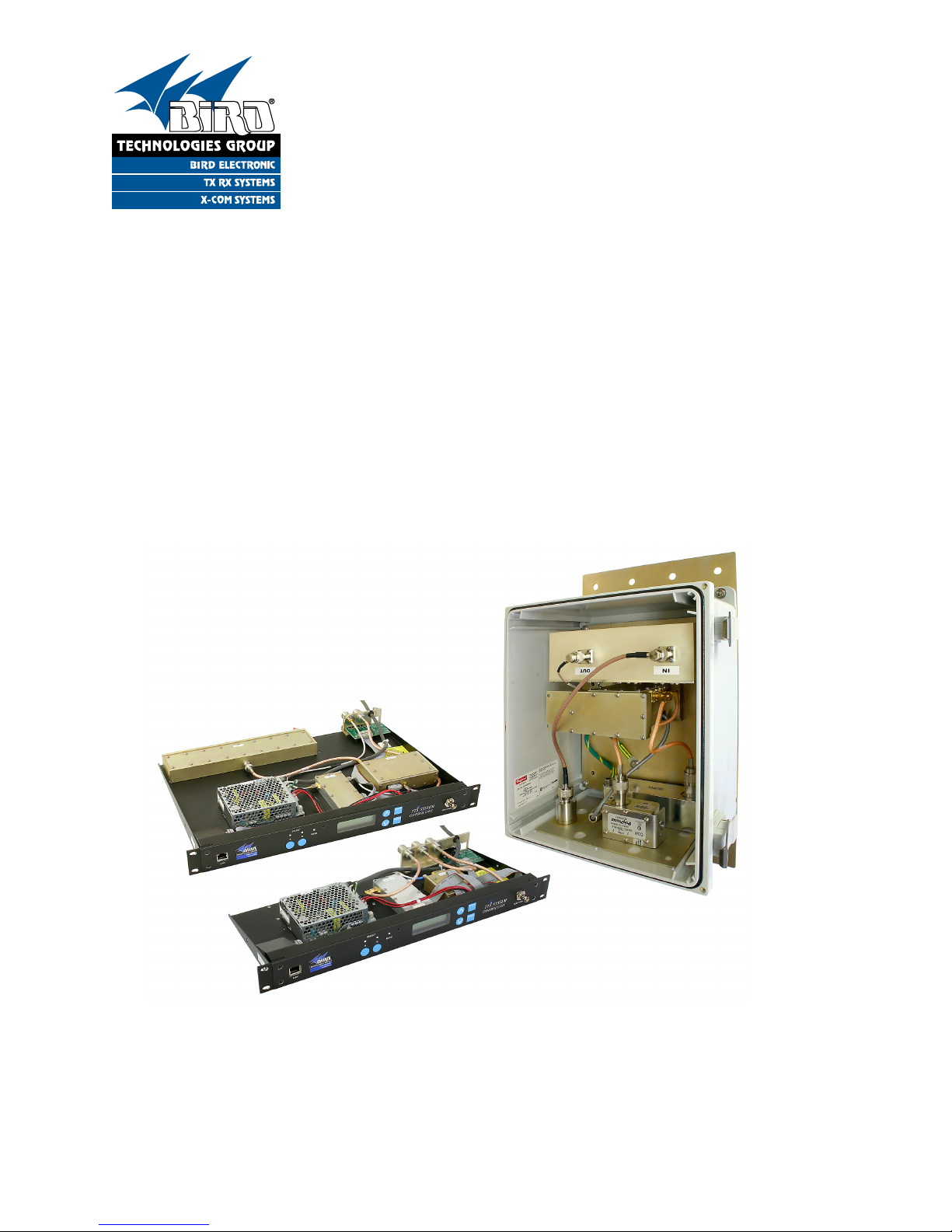
General Description ............................................................................................ 1
Tower Top Box .................................................................................................... 2
Base Control Unit ................................................................................................ 3
Base Control Unit Styles..................................................................................... 3
MCU .................................................................................................................... 3
Functional Block Diagram.................................................................................. 3
CMU .................................................................................................................... 9
Functional Block Diagram.................................................................................. 9
Unpacking .......................................................................................................... 10
Pre-Installation Checkout ................................................................................. 10
Mechanical Inspection ..................................................................................... 10
Initial Power-up Test .........................................................................................10
Bench Testing ................................................................................................... 11
Installation.......................................................................................................... 13
Test Transmission Line ..................................................................................... 13
Installing the System ........................................................................................ 14
Installing the Tower-Top Box ........................................................................... 14
In-building Lightning Arresters .......................................................................... 18
Installing the Base Control Unit ........................................................................ 18
Interference and IM Considerations..................................................................20
Feedline Data ..................................................................................................... 20
Optimizing the System ...................................................................................... 20
Attenuation Settings ......................................................................................... 21
Reserve Gain..................................................................................................... 21
Receiver Multicoupler Distribution (MCU Only) ................................................. 21
Setting the MCU Reserve Gain Attenuation ...................................................... 21
Setting the CMU Reserve Gain Attenuation ...................................................... 22
GTR8000 Attenuator Adjustment .................................................................... 23
Reserve Gain Adjustment Procedure ................................................................ 23
Setting Distribution Attenuation (MCU Only) ..................................................... 24
Adjustment Procedure ..................................................................................... 24
Spectrum Analysis ............................................................................................ 24
Procedure for Spectral Analysis ........................................................................ 25
Operational Tests (Sensitivity and Degradation) ........................................... 27
Front Panel Test Port ........................................................................................ 27
Tower Top Amplifier Inputs................................................................................ 27
Static System Sensitivity ................................................................................... 27
Measuring Static Sensitivity (Load Connected) ................................................. 27
Effective System Sensitivity............................................................................... 30
Measuring Effective Sensitivity (Antenna Connected)....................................... 30
Degradation ....................................................................................................... 30
Routine Operation ............................................................................................. 30
Amplifier Monitoring ........................................................................................... 31
LCD Display....................................................................................................... 31
Current Draw ................................................................................................... 31
TTA Temperature ............................................................................................ 31
Software Version ............................................................................................. 31
Front Panel LED’s ............................................................................................. 32
Form-C Contacts ...............................................................................................32

Table of Contents Manual 7-9487 - 3 05/05/11
Alarms ................................................................................................................ 32
The Test Mode ................................................................................................... 33
Set LNA X Active ...............................................................................................33
Terminate LNA X ............................................................................................... 33
Un-Terminate LNA X ......................................................................................... 33
System Troubleshooting ..................................................................................34
Performance Degradation ................................................................................ 34
Hardware Problems .......................................................................................... 35
Lightning and Lightning Arresters ................................................................... 35
Vandalism ....................................................................................................... 35
AC Line Fuse .................................................................................................... 35
Periodic Maintenance........................................................................................ 35
Recommended Spare Parts .............................................................................. 35
Optional Equipment .......................................................................................... 35
Multicoupler Expansion Deck ............................................................................35
16 to 32 Channel Expansion ...........................................................................35
16 to 48 Channel Expansion ...........................................................................36
Narrowband Filter .............................................................................................. 37
Installing Narrowband Filter (MCU systems) ..................................................... 38
Installing Narrowband Filter (CMU system)....................................................... 38
Figures and Tables
Figure 1: Front view of the tower-top box ............................................................ 1
Figure 2: Front view of the Base Control Unit ...................................................... 3
Figure 3: Top view of the MCU ............................................................................. 5
Figure 4: Back view of the MCU ........................................................................... 5
Figure 5: Functional block diagram of the MCU ................................................... 6
Figure 6: Top view of the CMU ............................................................................. 7
Figure 7: Back view of the CMU ........................................................................... 7
Figure 8: Functional block diagram of the CMU ................................................... 8
Figure 9: System cable connections..................................................................... 9
Figure 10: Initial power-up test ........................................................................... 10
Figure 11: Boot-up sequence ............................................................................. 11
Figure 12: Default display................................................................................... 11
Figure 13: Menu selections ................................................................................ 12
Figure 14: MCU test equipment interconnection for “bench testing” ................. 13
Figure 15: CMU test equipment interconnection for “bench testing” ................. 14
Figure 16: MCU System installation guidelines ................................................. 15
Figure 17: CMU System installation guidelines ................................................. 16
Figure 18: System installation guideline notes ................................................... 17
Figure 19: Tower-top box mechanical details .................................................... 18
Figure 20: Application of rubber splicing tape ................................................... 18
Figure 21: CMU Alarm terminals ....................................................................... 19
Figure 22: MCU Alarm Terminals ....................................................................... 19
Figure 23: MCU reserve gain attenuation level ..................................................22
Figure 24: Adjusting GTR8000 attenuators ........................................................ 23
Figure 25: Testing the MCU output spectrum ..................................................... 25
Figure 26: Testing the CMU output spectrum ..................................................... 26
Figure 27: Maximum signal level mask ............................................................. 26
Figure 28: Calculating actual sensitivity ............................................................. 28

Table of Contents Manual 7-9487 - 3 05/05/11
Figure 29: Using the test port to measure MCU sensitivity ................................ 29
Figure 30: Using the test port to measure CMU sensitivity ................................ 29
Figure 31: Schematic representation of Form-C contacts .................................. 32
Figure 32: Optional expansion deck (75-83H-428B) .......................................... 36
Figure 33: Optional expansion deck (75-83H-428B-32) .....................................37
Figure 33: Optional filter interconnect diagram................................................... 38
Figure 34: Connecting the narrowband filter....................................................... 39
Table 1: System Specifications ............................................................................. 1
Table 2: Tower Box Specifications......................................................................... 2
Table 3: MCU Specifications ................................................................................. 4
Table 4: CMU Specifications ................................................................................. 4
Table 5: Bench Test Results................................................................................ 11
Table 6: Distribution Attenuation Settings ...........................................................24
Table 7: Amplifier Status ..................................................................................... 31
Table 8: Typical Current Readings ...................................................................... 31
Table 9: Troubleshooting Guide .......................................................................... 34
Table 10: Optional Narrowband Filters................................................................ 38
Appendixes
Appendix A: Front Panel Ethernet Connectivity ................................................. 40
Ethernet Connectivity .......................................................................................... 40
Direct Connection .............................................................................................. 40
Required Equipment ........................................................................................ 40
Procedure ........................................................................................................ 40
Networked Connection ...................................................................................... 41
Required Equipment ........................................................................................ 43
Procedure ........................................................................................................ 43
TTA Network Port Security ................................................................................ 45
Data Encryption ............................................................................................... 45
SNMP Support Disabled..................................................................................46
Telnet Security ................................................................................................. 46
Changing the Telnet Port Password................................................................... 46
Appendix B: Changing Your Service Computers IP Address............................. 47

Table of Contents Manual 7-9487 - 3 05/05/11

TX RX Systems Inc. Manual 7-9487-3 05/05/11 Page 1
GENERAL DESCRIPTION
Your Bird Technologies Group, TXRX Systems
brand Tower Top Amplifier System provides the
highest degree of reliability available in a Tower
Top Amplifier (TTA). The system uses quadrature-
coupled amplifiers (also called balanced amplifiers)
to create a redundant amplifier configuration. Each
quad-amplifier provides two simultaneously used,
essentially parallel paths of amplification. Failure of
one of these paths of amplification results in an
overall gain reduction of only 6 dB.
The system is composed of two components
including a tower top box (TTA) which incorporates
filtering and a pair of low noise amplifiers. These
amplifiers establish superior noise figure prior to
feedline losses. The tower top box is mounted on
the tower close to the antenna. The second com-
ponent of the system is the base control unit which
is located in the control room.
The system also supplies automatic backup-ampli-
fier switching in the tower top box. Fault detection
Figure 1: Front view of the tower top box. Door removed for clarity.
3-22658
LNA
Assembly
Hinge
8-21183
Lightning
Arrester
8-21514
Lightning
Arrester
8-21549
Lightning
Arrester
8-23273
Filter
Do NOT Adjust
Tuning Rods
Locking
Clasp
Hold-down
Screw
Parameter Specification
Bandwidth 792 - 824 MHz
Noise Figure 3.5 dB max
3rd order IIP > 15.0 dBm
Reserve Gain Fully settable by
electronic attenuator
Rejection <110 dB Min, 120 db Nom
@776 and 851 MHz
AC Current
(model 428B-83H-01-M) 340 mA (typ) @120 VAC
AC Current
(model 428B-83H-01-CG) 215 mA (typ) @ 120 VAC
DC Current
(model 428B-83H-01-M-48) 780 mA (typ) @48 VDC
DC Current
(model 428B-83H-01-CG-48) 550 mA (typ) @ 48 VDC
Table 1: System specifications.
13 dB reserve gain and
maximum 6 dB transmission line loss assumed

TX RX Systems Inc. Manual 7-9487-3 05/05/11 Page 2
circuitry continuously monitors the DC power oper-
ation of the primary quad-amplifier and automati-
cally switches to the identical secondary quad-
amplifier if conditions indicate a primary malfunc-
tion. Fault detection circuitry also provides at-a-
glance status reporting, with front-panel LED’s and
an LCD display. The system specifications are
listed in Table 1.
Tower Top Box
The quad-amplifier in the tower top box amplifies
the weak received signal before the signal enters a
long and lossy transmission line, thus preventing
the line loss from degrading the signal-to-noise
ratio. The quadrature amplifiers have a separate
power circuit for each half of the amplifier which
provides component redundancy as well as unsur-
passed IM performance. Microprocessor controlled
fault detection circuitry in the tower top box pro-
vides continuous monitoring and switching of each
quad amplifier while sending operational data to
the base unit front panel for at-a-glance status
reporting and form-C contact switching for alarm
integration. Included in the tower top box is a pre-
selector filter, amplifier “A” and amplifier “B,”
switching circuitry, control board and lightning
Electrical Specifications
Frequency Range 792 to 824 MHz
Net Gain 23 dB (typ)
Noise Figure 2.7 dB (typ)
Backup Amplifier Switching Solid State RF Switch
Integrated Test Port Isolation 33.5 dB (typ)
Preselector Type
Loss
Rejection
7-pole TEM Bandpass
with cross-coupling
<0.8 dB (typ)
>60 dB @ 776 and 851 MHz
LNA Type
Gain
Noise Figure
3rd Order Input IP
2-stage Quadrature
integrated into filter
26 dB (typ)
1.2 dB (typ)
18 dBm (typ)
Impedance 50 Ohms
Antenna Port VSWR 2 : 1
Power Requirements 12 VDC @ 1.25 A
Lightning Protection Impulse Suppressor on all external connectors
Operating Temp Range -30°C to +60°C *
Mechanical Specifications
Enclosure Modified NEMA 4x:
weather resistant
Connectors N -female
Dimensions (HWD)
not including mounting tabs and connectors
18” x 6” x 6”
(457 x 152 x 152 mm)
Net Weight 17.5 lbs
*The tower top amplifier will function up to 70°C without shutting down. However, the specifications are not
guaranteed.
Table 2: Tower box specifications. Values are typical unless noted otherwise.

TX RX Systems Inc. Manual 7-9487-3 05/05/11 Page 3
arresters (see Figure 1). The specifications for the
tower box are listed in Table 2.
Base Control Unit
The ground-mounted Base Control Unit is intended
for 19-inch rack mounting. It houses alarm indica-
tors, a power supply or DC to DC converter, and a
display panel to provide visual feedback on the
system’s operating status. There is also a test port
input for providing an RF signal path for loopback
tests. The front panel display shows status infor-
mation such as amplifier current draw and temper-
ature. In addition the display is used to provide a
user interface for adjustments such as setting
reserve attenuation. The current draw values of
each amplifier in the system is displayed by the
base control unit. Also included in the system is a
Webpage User Interface for controlling and moni-
toring of amplifier currents, alarms, and attenua-
tors. The webpage user interface is accessed
through the front panel LAN connector. Refer to
Appendix A for instructions on accessing this fea-
ture. A photograph of the front panel is shown in
Figure 2.
BASE CONTROL UNIT STYLES
The base control unit is available in two styles
including the Multicoupler Control Unit (MCU) and
the Control Management Unit (CMU). The tower
top box used in your system is the same regard-
less of which style base control unit you have. The
front panel of your base control unit is the same for
both MCU and CMU styles.
MCU
The MCU style base control unit is designed to
include a receiver multicoupler function in addition
to the base controlling functions. The MCU has the
built-in capability to split the received RF signal
from the tower top box to 16 individual receivers. In
addition, there is also an expansion port which
allows the additional expansion of the system up to
32 ports. The specifications for the MCU are listed
in Table 3. A top view and a back view of the MCU
deck are shown in Figures 3 and 4 respectively.
FUNCTIONAL BLOCK DIAGRAM
The functional block diagram of the system is
shown in Figure 5. RF signals enter the tower top
box and are passed thru a multi-resonator prese-
lector tuned to pass 792 to 824 MHz. After filtering
the signals are amplified by the active tower top
LNA (either amp A or B depending on user selec-
tion) before passing through the main transmission
line to the ground based control unit. The input of
each tower top LNA has a test signal port which
allows test signals from the base control units front
panel test port to be coupled into the systems RF
signal path. There is a 33.5 dB loss associated with
test signals injected into the system. The user has
Figure 2: Front view of the Base Control Unit.
Note: Both the MCU and CMU style base control units use the same front panel.
Status LED’s
Contrast
Adjust Up
Button
Cancel
Button
LAN
Port Amplifier
Select
Buttons
Display Down
Button
Enter
Button
Test
Port

TX RX Systems Inc. Manual 7-9487-3 05/05/11 Page 4
the ability via software interface to switch the tower
top LNA’s input, between either the antenna or an
internal 50 Ohm load. This feature gives field engi-
neers the ability to perform system sensitivity tests
from the ground with or without site noise being
coupled into the system via the antenna.
RF signals from the tower top box are applied at
the rear of the MCU style base control unit at the
TRANS input connector. After passing onto the
deck they are applied to a modem assembly which
is used to couple and de-couple the 2.176 MHz
modem subcarrier communications between the
base and tower top CPU’s. The modem assembly
is also used to inject onto the main transmission
line, the +12 VDC that is required to power the
tower box circuitry.
RF signals leave the modem assembly and are
routed to an amplifier assembly where they pass
through a wideband ceramic filter located in the
input circuit of the assembly. Following the filter is
a variable attenuator which allows adjustment of
Electrical Specifications
Frequency Range 792 to 824 MHz
Impedance 50 Ohms
VSWR <2 : 1
Connectors
to TTA
to BTS
Test Port input
N - Female
N - Female
BNC - Female
Reserve Gain
electronic attenuator
0 to 15.5 dB
in 0.5 dB steps
Alarm Contacts
Two sets of Form-C Con-
tacts
Nominal 2A @ 30 VDC
or 0.5A @125 VAC
I/O Ethernet
Power Requirements
Model 428-83H-01-C-110
Model 428-83H-01-C-48
90 - 240 VAC @ 50/60 Hz
-48 VDC
Operating Temp Range 0°C to + 50°C
Mechanical Specifications
Enclosure Standard EIA 19” Rack
Mount
Dimensions (HWD) 1 RU x 19” x 8”
(38 x 483 x 203 mm)
Net Weight 10.5 lbs
Table 4: CMU specifications. Values are typical unless
noted otherwise.
Electrical Specifications
Frequency Range 792 to 824 MHz
Multicoupler Net Gain +1 dB typ; 0 dB min
Distribution Amp Type
Gain
Noise Figure
1 dB compression point
3rd Order Output IP
Quad-coupled dual stage
23 dB
4 dB
27 dBm
46 dBm
Number of Outputs
Split Loss
16 or 32
18 dB
Impedance 50 Ohms
VSWR <2 : 1
Connectors
to TTA
to BTS
Test Port input
N - Female
BNC-Female
BNC - Female
Reserve Gain
electronic attenuator
0 to 15.5 dB
in 0.5 dB steps
Distribution
electronic attenuator
0 to 3 dB
in 0.5 dB steps
Alarm Contacts Two sets of Form-C Contacts
Nominal 2A @ 30 VDC
or 0.5A @125 VAC
I/O Ethernet
Power Requirements
Model 428-83H-01-M
Model 428-83H-01-M-48
90 - 240 Vac @ 50/60 Hz
-48 VDC
Operating Temp Range 0°C to + 50°C
Mechanical Specifications
Enclosure Standard EIA 19” Rack Mount
Dimensions (HWD) 1 RU x 19” x 14”
(38 x 483 x 356 mm)
Net Weight 11.5 lbs
Table 3: MCU specifications. Values are typical unless
noted otherwise.

TX RX Systems Inc. Manual 7-9487-3 05/05/11 Page 5
Figure 4: Back view of the MCU.
AC or DC
Cord
(Model Dependent)
Alarm
Terminals Expansion
Port
To Station Receivers
Ground
Lug
Test
Cable
here
Main
Cable
here
Figure 3: Top view of the MCU.
3-23339
16-Way Divider
w/ Expansion Port
3-22914
Modem
Assembly
3-23416
Rear Panel
Board
3-21450
Amplifier
Assembly
3-22951
Front Panel Board
(under shroud)
3-21476
Ethernet
Board
8-21515
Power
Supply

TX RX Systems Inc. Manual 7-9487-3 05/05/11 Page 6
50
LNA
A
Surge
792-824
Filter
Amp
Select
SwitchA Term
Switch
B Term
Switch
Control
Board
CPU
Amp
Select
Switch
+12VDC+12VDC
3 dB
50
LNA
B
Surge
RS-485 Tap
DC Tap
RS-485
+12VDC
Antenna
Main Test
428B
TTA Assembly
792-824 MHz
Filter
Alarm
NC
COM
NO
NC
COM
NO
Alarm
Modem
DC Inject
CPU
Front
Panel
Assembly
Expansion Port
16 Way Divider
2 Way Divider
Variable
Attenuator
Variable
Attenuator
LNA
+12VDC
RS-485
+12VDC
Power
Supply
Test Port
Main Test
428B
MCU Assembly
Figure 5: Functional block diagram of the MCU TTA system.

TX RX Systems Inc. Manual 7-9487-3 05/05/11 Page 7
Figure 7: Back view of the CMU.
AC or DC
Cord
(model dependent)
Alarm
Interface
Test
Cable
here
Ground
Lug
RF Out to
GTR-8000
Main
Cable
here
Figure 6: Top view of the CMU.
3-21532
Filter
Attenuator
3-22951
Front Panel Board
(under shroud)
3-21476
Ethernet
Board
3-23070
Rear Panel
Board
3-22914
Modem
Assembly
8-21515 Power Supply
(model 428B-83H-01-C-110)
3-21516 DC-DC Converter
(model 428B-83H-01-C-48)

TX RX Systems Inc. Manual 7-9487-3 05/05/11 Page 8
50
LNA
A
Surge
792-824
Filter
Amp
Select
SwitchA Term
Switch
B Term
Switch
Control
Board
CPU
Amp
Select
Switch
+12VDC+12VDC
3 dB
50
LNA
B
Surge
RS-485 Tap
DC Tap
RS-485
+12VDC
Antenna
Main Test
428B
TTA Assembly
792-824 MHz
Filter
Alarm
NC
COM
NO
NC
COM
NO
Alarm
Modem
DC Inject
CPU
Front
Panel
Assembly
Variable
Attenuator
+12VDC
RS-485
+12VDC
Power
Supply
Test PortRF Output
Main Test
428B
CMU Assembly
Figure 8: Functional block diagram of the CMU TTA system.

TX RX Systems Inc. Manual 7-9487-3 05/05/11 Page 9
the channels Reserve Gain attenuation. The next
stage is a distribution amplifier which is used to
overcome splitter losses in the base control unit.
Following the amplifier is a variable attenuator that
allows adjustment of the Distribution attenuation.
Signals are then applied to a 16-Way splitter for
distribution to the station receivers.
CMU
The CMU style base control unit is designed to
interface the TTA to the GTR8000 radio system
and does not include the receiver multicoupler
function. There are no individual receiver ports or
expansion ports provided since the receive distri-
bution function is performed in the GTR8000. The
specifications for the CMU are listed in Table 4. A
top view and a back view of the deck are shown in
Figures 6 and 7 respectively.
FUNCTIONAL BLOCK DIAGRAM
The functional block diagram of the system is
shown in Figure 8. RF signals enter the tower top
box and are passed thru a multi-resonator prese-
lector tuned to pass 792 to 824 MHz. After filtering
the signals are amplified by the active tower top
LNA (either amp A or B depending on user selec-
tion) before passing through the main transmission
line to the ground based control unit. The input of
each tower top LNA has a test signal port which
allows test signals from the base control units front
panel test port to be coupled into the systems RF
signal path. There is a 33.5 dB loss associated with
test signals injected into the system. The user has
the ability via software interface to switch the tower
top LNA’s input, between either the antenna or an
internal 50 Ohm load. This feature gives field engi-
neers the ability to perform system sensitivity tests
from the ground with or without site noise being
coupled into the system via the antenna.
RF signals from the tower top box are applied at
the rear of the CMU style base control unit at the
TRANS input connector. After passing onto the
deck they are applied to a modem assembly which
is used to couple and de-couple the 2.176 MHz
modem subcarrier communications between the
MCU
CMU
Tower Top Box
Main
Trans
Test
Port
Antenna
Test
Port
Test Main
Transmission
Main
Transmission
Station
Receivers
Main
Trans
Test
Port
Figure 9: Cable connections for system components.

TX RX Systems Inc. Manual 7-9487-3 05/05/11 Page 10
base and tower top CPU’s. The modem assembly
is also used to inject the +12 VDC onto the main
transmission line that is required to power the
tower box circuitry.
RF signals leave the modem assembly and are
routed to a filter/attenuation assembly where they
pass through a wideband ceramic filter located in
the input circuit of the assembly. Following the filter
is a variable attenuator which allows adjustment of
the channels Reserve Gain attenuation. Signals
leave the filter/attenuation assembly and are sent
to the RF Output connector on the back of the deck
where they are available for the GTR-8000 system.
UNPACKING
Each major component of the TTA system is indi-
vidually packaged and shipped via motor freight or
UPS. It is important to report any visible damage to
the carrier immediately. It is the customer's respon-
sibility to file damage claims with the carrier within
a short period of time after delivery (1 to 5 days).
PRE-INSTALLATION CHECKOUT
The following pre-installation tests should be per-
formed after unpacking the system to verify nothing
has loosened during transit. Additionally, the sys-
tem should be made operational on the bench with
all components at ground level to verify proper
electrical performance. Figure 9 illustrates all of
the cable connection points for both the tower top
box and the MCU and CMU base control units.
The tower top box should NOT be
installed on the tower until all of the
pre-installation tests are successfully
completed.
Mechanical Inspection
Open the tower top box by loosening the door
clamps and removing the two corner hold-down
screws. Make sure that all of the connectors inside
the box are tight. In addition, it is advisable to
check the tightness of the hold-down screws for the
various assemblies to insure nothing loosened dur-
ing shipment. It is important to re-tighten the tower
box door correctly so that the door gasket seal is
maintained. Insure that the moisture vent holes at
the bottom of the box are unobstructed. Likewise,
check all of the cable connections on the base con-
trol unit to insure that they are all properly mated to
their associated plugs.
CAUTION:The wide band filter in
the tower top box is factory tuned
and must not be field adjusted. Field
tuning of this filter is not required. Do
not adjust the tuning slugs of the
amplifier/filter assembly.
Initial Power-Up Test
To perform the initial power-up test the system
should be temporarily interconnected at ground
level using short temporary cables. Figure 10
shows the temporary equipment hookup for initial
power-up testing of the MCU. Hook-ups for the
CMU are similar (test to test and main to main).
NOTE
Test
Test
Front Panel
Test Port
Main
Main
Tower Top Box
MCU
Figure 10: Initial power-up test.
MCU style base control unit shown as example.

TX RX Systems Inc. Manual 7-9487-3 05/05/11 Page 11
Once the equipment is temporarily interconnected
then power is applied to the system by plugging the
control unit’s AC cord into a suitable AC outlet
(models 428B-83H-01-M-110 and 428B-83H-01-C-
110) or by connecting the DC power cable to a suit-
able -48 VDC supply (model 428B-83H-01-M-48
and 428B-83H-01-C-48). The following start-up
sequence occurs.
1) At turn-on, the three front panel status LED’s
will all glow a steady red while the display panel
shows a row of solid boxes on the top display
line. This will last for about 10 seconds while
the systems micro-controllers boot-up.
2) During the next 5 seconds the base control unit
will establish communications with the tower
box. The front panel status LED’s will occasion-
ally flash green. The display panel will present
the message “Connecting to Tower Controller”
and then will briefly flash the base control unit’s
current software version. See Figure 11.
3) After the power-up sequencing is complete the
screen should show the default display as
shown in Figure 12. The status LED for each
active amplifier will glow a steady green and the
status LED for the inactive (stand-by) LNA will
be dark.
The tower top amplifier system is software directed
so control of the system is accomplished via user
interface with the front panel using the display
screen and the four menu selection buttons. A flow
chart showing all of the possible user menu selec-
tions is shown in Figure 13.
Bench Testing
The purpose of the bench test is to verify that all of
the system components are working correctly and
to measure the systems sensitivity before climbing
the tower to mount the tower top box. One station
receiver is selected and the test is performed at
this frequency. Short temporary cables are used to
interconnect all components. A SINAD meter is
used for the test (or a bit error rate meter if
required) along with a signal generator.
1) The stand-alone receiver sensitivity is mea-
sured and recorded first. Record the value in
Table 5.
2) Connect the equipment as shown in Figures 14
or 15. Be sure that the signal generator is setup
for a 3 KHz deviation with a 1000 Hz tone (ana-
log) or proper pattern for BER testing.
3) Measure and record the systems bench test
static sensitivity in table 5. The sensitivity value
will vary depending on the amount of internal
programmable attenuation selected via soft-
ware interface. The bench test measurement
should be taken with the default values selected
Test Performed Result
Stand Alone
Receiver
Sensitivity
dBm
* Bench Test
Static
Sensitivity dBm
Model Number
(Tower Top Box)
Serial Number
(Tower Top Box)
Table 5: Bench Test Results.
* Default Reserve Gain Attenuation (3.0 dB)
* Default Distribution Attenuation (1.0 dB)
Figure 12: Default display.
Figure 11: Base Control Unit software version is dis-
played briefly during the boot-up sequence.

TX RX Systems Inc. Manual 7-9487-3 05/05/11 Page 12
RESERVE GAIN
DISTRIBUTION
MAIN LINE LOSS
TEST LINE LOSS
STATIC W/LOAD
REFERENCE W/ANT
AS AN EASY REFERENCE
RECORD VALUES HERE
Functions within
Red Outlined Boxes
are disabled in CMU
version.
YELLOW
INDICATES
RECORDABLE
VALUE
After pressing the ENTER Button
the Base Control Unit will re-boot,
then return to the Default Display.
CANCEL
ENTER
UP-ARROW
DOWN-ARROW
KEY TO BUTTONSKEY TO BUTTONS
C
E
Changes
Value
Changes
Value
Changes
Value
Changes
Value
Changes
Value
Changes
Value
NOTE
428B-83H-01-X
TX RX SYSTEMS INC
LNA X ACTIVE
A CURRENT XXXmA
B CURRENT XXXmA
BASE CURRENT
XXXX mA
TTA TEMPERATURE
+/- XX DEGREES C
BASE V X.XX
TOWER V X.XX
INITIALIZE
ENTER TO RESTART
TEST
ENTER TO SELECT
ATTENUATORS
ENTER TO SELECT
FEEDLINE DATA
ENTER TO SELECT
SENSITIVITY
ENTER TO SELECT
RESERVE GAIN
ENTER TO ADJUST
MAIN LINE LOSS
ENTER TO ADJUST
STATIC W/LOAD
ENTER TO ADJUST
Manual Mode
RESERVE GAIN
X.X dB
Automatic Mode
RESERVE GAIN
AUTO MODE
MAIN LINE LOSS
X.X dB
STATIC W/LOAD
-XX.X dB
DISTRIBUTION
ENTER TO ADJUST
TEST LINE LOSS
ENTER TO ADJUST
REFERENCE W/ANT
ENTER TO ADJUST
DISTRIBUTION
X.X dB
TEST LINE LOSS
XX.X dB
REFERENCE W/ANT
-XX.X dB
SET LNA A ACTIVE
ENTER TO CONFIRM
SET LNA B ACTIVE
ENTER TO CONFIRM
TERMINATE LNA A
ENTER TO CONFIRM
TERMINATE LNA B
ENTER TO CONFIRM
UNTERM LNA A
ENTER TO CONFIRM
UNTERM LNA B
ENTER TO CONFIRM
Return to
Default Display
428B-83H-01-X Menu System
DEFAULT
DISPLAY
E
EE
E E
E E
E
E
C
E
C
E
C
C
C
C
C
C
C
E
C
E
C
EE
E
E
C
E
C
Figure 13: 428B-83H-01-X menu selections.
This manual suits for next models
4
Table of contents
Other BIRD Amplifier manuals