BKL Air Conditioner BKL line FX i10 Guide

GB
INSTALLATION AND USE MANUAL
AIR CONDITIONERS
Flash FX i10/i11 Inverter
Without Outdoor Unit
COOLING


33
EN
Compliance
This unit complies with European directives:
•Low voltage 2014/35/EU
•Electro-magnetic compatibility 2014/30/EU
•Use restrictions of hazardous substances in electrical
and electronic equipment 2011/65/EC (RoHS2)
•Waste electrical and electronic equipment 2012/19/
EC (WEEE).
•Waste electrical and electronic equipment 2012/19/
EC (WEEE).
•Energy consumption indication on the labels of energy-
related products 2010/30/EU
•ErP Directive 2009/125/EC and regulation 2012/20EC
U
User
- Refers to pages containing instructions or information
for the user.
I
Installer
- Refers to pages containing instructions or information
for the installer.
S
Service
- Refers to pages containing instructions or information
for the CUSTOMER TECHNICAL ASSISTANCE
SERVICE installer.
Warning
- It indicates actions that require caution and a suitable
preparation.
Do Not
- Refers to actions that absolutely must not be
performed.
Enviromental safeguard information!
This equipment contains fluorinated greehouse gases covered
by Kyoto Protocol. It should only be serviced or dismantled by
professional trained personnel.
Directive 2012/19/EC (WEEE): Information for users
This product complies with EU Directive 2012/19/EC.
The barred bin symbol on the appliance indicates that the pro-
duct, requiring separate treatment to household waste after its
normal working life, must be taken to a waste-sorting centre for
electrical and electronic appliances or returned to the retailer at
the time of purchasing a new equivalent appliance.
The user is responsible for taking the appliance to the appro-
priate waste collection centre at the end of its working life.
Correct waste sorting, with the discarded appliance being sent
for recycling, treatment and compatible environmental disposal
helps prevent any negative effects on the environment and
health, and encourages the recycling of product materials.
For further detailed information regarding available collection
systems, please contact your local waste disposal service or
the shop where you made your purchase.
Disposal rules for the old air conditioner
Before disposing of your old air conditioner, make sure that it is
off and unplug it. The refrigerant it contains requires a special
procedure for disposal. Materials of value in the air conditioner
can be recycled. Contact local authorities or the waste dispos-
al facility for more information. Make sure you do not damage
the pipes of the air conditioner before you take it to the waste
disposal facility. Help protect the environment by following a
correct, non-polluting method of disposal.
Disposal rules for the new air conditioner
packaging
All of the air conditioner packing materials can be disposed of
without harming the environment. The cardboard box must be
cut into pieces and delivered to a paper collection container. The
plastic and polystyrene packaging does not contain fluorine or
hydrocarbons.
All of these materials can be deposited in a waste dump and
recycled after proper treatment. Contact your local authorities
for information on waste disposal.
Battery disposal
The batteries have been designed and produced
with high quality materials and the components
can be recycled and/or re-used.
The symbol of the crossed-out rubbish bin
indicates that the product (batteries) at the end
of its useful life must be handled separately
from domestic waste and must be sent to a separate waste
collection center, as provided by the European Community
2006/66EC, art. 20 and annex II.
If under the bin there is a chemical symbol, this indicates that
the batteries have a certain concentration of heavy metal.and it
will be indicated as follows:
Hg: mercury (0,0005%), Cd: cadmium (0,002%), Pb: lead
(0,004%)
•Energy consumption indication on the labels of energy-
related products 2010/30/EU
Editorial pictograms
Safety pictograms

34
General
1.1 General ...................................................................... 35
1.2 Fundamental safety rules ..................... . . . . . . . . . . . . . . . . . . . . . . . . . . . . . . . . . . . . 36
1.3 Description.................................................................... 37
1.4 Receipt and unpacking . . ..................... . . . . . . . . . . . . . . . . . . . . . . . . . . . . . . . . . . . 37
1.5 Storage ...................................................................... 37
1.6 Handling ..................................................................... 37
1.7 Shipping dimensions and weight.................................................... 38
1.8 Supplied components ......................... . . . . . . . . . . . . . . . . . . . . . . . . . . . . . . . . . . 38
1.9 Unit parts ..................................................................... 39
1.10 How to Remove the aesthetic parts.................................................. 39
Installation
2.1 Installation mode................................... . . . . . . . . . . . . . . . . . . . . . . . . . . . . . 40
2.2 Choosing the position of the unit .................................................... 40
2.3 Assembling the unit ............................. . . . . . . . . . . . . . . . . . . . . . . . . . . . . . . . . 41
2.4 Assembling air ducts and external shutters ............................................ 43
2.5 Mounting the appliance on the bracket ............................................... 44
2.6 Electrical connection .......................... . . . . . . . . . . . . . . . . . . . . . . . . . . . . . . . . . . 45
2.7 High/low installation configuration ................................................... 46
2.8 Setting cool only or heat only modes . . ... . . . . . . . . . . . . . . . . . . . . . . . . . . . . . . . . . . . . . . . . . . . . 47
2.9 Key Lock touch screen display and brightness adjustment ................................. 47
2.10 Operations tests and anomaly diagnosis .............................................. 47
2.11 Hotel function .................................... . . . . . . . . . . . . . . . . . . . .... . . . . . . 47
2.12 Heating operation (only for FLASH FX i11 model) 48
2.13 Wiring diagram ................................................................ 50
Maintenace
3.1 Periodic Maintenance ......................................................... . . 52
3.2 Troubleshooting ................................. . . . . . . . . . . . . . . . . . . . . . . . . . . . . . . . 53
3.3 Technical specifications .......................................................... 54
User Manual
4.1 Warnings ..................................................................... 55
4.2 Management of the appliance with the touch-screen display ............................... 55
4.3 Managing the appliance with the remote control ........................................ 56
4.4 Description of machine functioning ...... . . . . . . . . . . . . . . . . . . . . . . . . . . . . . . . . . . . . . . . . . . . . 56
4.5 Advice for energy saving .......................................................... 58
4.6 Problem diagnostic ............................ . . . . . . . . . . . . . . . . . . . . . . . . . . . . . . . . . 58
Product fiche 59
Guarantee Certificate .......................... . . . . . . . . . . . . . . . . . . . . . . . . . . . . . . . . . . 61

35
1.1
EN
General warning
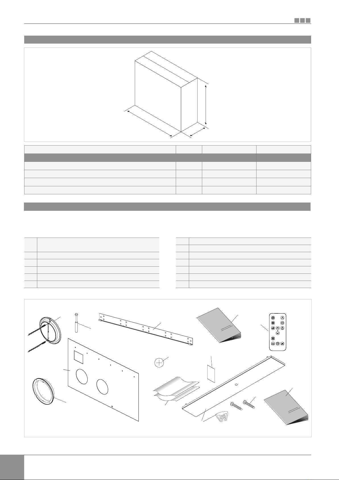
After unpacking, check that the contents are intact
and that all parts are included. If they're not, please
contact the Agent who sold you the appliance.
The appliance must be installed by an authorised
company. Once the work is done, it must issue a
declaration of conformity to the client in compliance
with current Regulations and with indications on the
instruction manual supplied with the appliance.
These appliances have been designed for
conditioning and/or heating rooms and they must be
destined solely for this purpose compatibly with their
performance characteristics.
The manufacturer refuses any contractual or extra-
contractual responsibilities for damage caused to
people, animals or things resulting from incorrect
installation, adjustment, maintenance or improper
use.
In the event of water leaks, turn off the main switch
and close the water taps.
Immediately call the Technical Assistance Service
or other qualified personnel and do not intervene
personally on the appliance.
If the temperature is set too low or too high, not only it
is unhealthy, but it is also a useless waste of energy.
Avoid prolonged direct contact with the air flow.
Do not leave the room closed for long. Open the
windows periodically to change the air.
This instruction booklet is an integral part of the
appliance and therefore it must be kept with care and
must ALWAYS accompany the appliance even when
the latter is transferred to another owner or user or
transferred to another system. If it gets damaged or
lost, please request another copy to the local BKL line
Technical Assistance Service.
Any repair or maintenance operations must be
performed by the Technical Assistance Service or by
qualified personnel in accordance with this booklet. Do
not modify or tamper with the appliance as this could
lead to dangerous situations and the manufacturer will
not be liable for any damage caused.
Attention. Cutting danger, please wear suitable gloves.
If conditions occur, please respect the rules for works
at height.
Refrigerant must always be recovered and never be
disposed directly into the environment.
Refrigerant must never be released into the
atmosphere.
The appliance is declared to have an IPX0 protection
rating, therefore, it cannot be installed outdoors or in
laundry rooms.
GENERAL
Refrigerant gas R 410 A
GWP 2087,5
Composition 50% Difluoromethane
50% Pentafluoroethane
Hazard indications
Major hazards Asphyxiation
Specific hazards Rapid evaporation can cause frostbite
First aid measures
General information Do not administer anything if patient has fainted
Inhalation Move to open air. - Administer oxygen or artificial respiration if necessary. - Do not administer adrenaline
or similar substances.
Contact with eyes Rinse thoroughly with plenty of water for at least 15 minutes and call a doctor.
Contact with the skin Wash immediately with plenty of water. - Remove contaminated clothing immediately.
Firefighting measures
Extinguishing methods Any
Specific hazards Increase in pressure
Specific methods Cool containers by spraying with water
Measures in case of accidental escape of gas
Individual precautions Evacuate personnel to area of safety - Ensure adequate ventilation - Use personal protective equipment
Environmental precautions Evaporation
Method of cleaning Evaporation
Handling and storage
Handling Ensure sufficient air changes and/or
measures/technical precautions use forced ventilation at places of work
Recommendations for safe use Do not breathe vapour or droplets
Storage Shut off carefully and keep in a cool, dry and well-ventilated place.
Keep in original containers.
Incompatible products: explosives, inflammable materials, Organic peroxide
Part of the refrigerant safety table

36
S
I
U
1.2 Fundamental safety rules
GENERAL
We would like to remind you that some fundamental
safety rules should be followed when using products
that work with electricity and water;
The unit can be used by children over the age of
8, and by people with reduced physical, sensory or
mental capabilities, or with no experience or necessary
knowledge, as long as they are monitored or after they
have received instructions on the safe use of the unit
and have understood the dangers involved.
Children must not play with the appliance.
The cleaning and maintenance that must be
performed by the user should not be carried out by
children without supervision.
It is forbidden to touch the appliance if barefoot or with
wet or humid parts of the body.
It is forbidden to clean the appliance without having
first disconnected the appliance from the mains power
supply by turning off the main switch.
It is forbidden to modify safety or adjustment devices
without authorisation and the indications from the
manufacturer.
It is forbidden to pull out or twist the electric cables
coming out of the appliance, even if they are
disconnected from the mains power supply.
It is forbidden to introduce objects and substances
through the air inlet and outlet grids.
It is forbidden to open the access doors to the internal
parts of the appliance without having turned off the
main switch first.
It is forbidden to dispose of and leave within the reach
of children the packing materials as they could be a
source of danger.
It is forbidden to climb onto the appliance and/or to
place any type of object on top of it.
Exposure controls/personal protection
Control parameters AEL (8-h TWA) = 1000 ml/m³
for each of the two components
Respiratory protection For gas recovery and maintenance work in tanks, use an independent breathing apparatus
The vapour is heavier than air and can cause suffocation by reducing the oxygen available for respiration
Eye protection Safety glasses
Hand protection Rubber gloves
Hygiene measures Do not smoke
Physical and chemical properties
Colour Colourless
Odour Similar to ether
Boiling point - 51.6 °C at atmospheric pressure
Flashpoint Non flammable
Relative density 1.063 Kg/l at 25 °C
Solubility in water 2.8 gm/l at 25 °C at atmospheric pressure
Stability and reactivity
Stability No reactivity if used in accordance with instructions
Materials to avoid Alkaline metals, alkaline-earth metals, granulated metallic salts, Al, Zn, Be, etc. in dust form
Hazardous decomposition products Halogenic acids, traces of carbonyl halides, ALC
Acute toxicity (R32) LC50/inhalation/4 hours/in rats = 760 l/m³
(R125) LC50/inhalation/4 hours/in rats = 800 l/m³
Side effects Inhalation of vapour at high concentration can produce asphyxiation or cardiac arrhythmia,
irregular pulse, palpitations, reduced circulation and even cardiac arrest.
Long-term toxicity Has not shown any carcinogenic, teratogenic or mutagenic effects, in experiments performed on animals
Ecological information
Global warming potential
HGWP (R11 = 1) R 125: 0.70 - R 32: 0.15
Ozone depletion potential
ODP (R11 = 1) 0
Considerations on disposal
Usable after reconditioning

37
S
I
U
1.3
1.4
1.5
1.6
EN
GENERAL
Description
FLASH is the new solution by BKL line, a significant step
towards reducing the aesthetic impact of air conditioners.
Being only 16 centimetres deep, FLASH is the thinnest
and less bulky in its category, therefore both the internal
and external aesthetic impact is kept to a minimum.
Optimised Capacities
The conditioning capacities of FLASH have been optimised
so as to obtain the right temperature for the best level of
comfort and, therefore, less consumption and less noise.
Thanks to the careful choice of sound insulation materials,
the noise is similar to that of a standard wall split unit and
consumption is drastically contained thanks to the new
direct current fan.
162 millimetre holes
An important choice not only design-wise, but also because
of a considerable installation advantage: it is easier to find
drilling tools as there's no need for professional ones, with
lower aesthetic impact.
BLDC inverter technology
We have perfected the inverter technology to offer the
best in terms of acoustic comfort (noise) and performance:
reduction of consumptions, maintenance of the best
temperature level and humidity level in the room.
Thanks to the use of the cutting edge BLDC (brushless
direct current) inverter regulation, vibrations have been
completely eliminated and acoustic emissions have been
lowered to exceptional levels.
Both ventilation motors are BLDC to reduce consumption
still further and make flow adjustment more precise.
Easy to install
FLASH can be installed on any perimeter wall either low or
high. Everything needed for installation (template, support
bracket, hole pipes and external grids), excluding the drill,
is included in the box.
Folding external grids
FLASH is equipped with folding grids activated by inlet
and outlet air. They open when the unit is working and
close when it's turned off. Better indoor comfort, less
dust, noise and pollution, less maintenance and even less
outdoor visibility.
Remote control and touch-screen display
In addition to the remote control, the touch-screen
display on the unit enables the setting of any function.
There's even a "lock" mode to avoid any improper use.
It is possible to deactivate the "heating" mode by simply
touching the screen. The unit then works in "cool only"
mode, without the need to use the condensation drain
pipe. The orientation of the air flaps can also be adjusted
by simply pressing one key.
Receipt and unpacking
The packing is made of suitable material and carried out
by expert personnel. All units are checked and tested and
are delivered complete and in perfect conditions, however
please perform the following instructions to check the
quality of shipping services:
- upon receipt, check if the box is damaged. If that is
the case, accept the goods with reservations and
keep photographic evidence of any damage found
- unpack and check the contents against the packing
list
- check that none of the parts have been damaged
during shipment.
Keep the packing at least for the whole length of
warranty should you need to ship the appliance to
the service centre for repair. Dispose of the packing
materials in compliance with current regulations on
waste disposal.
Storage
Handling
Store the box in a closed environment protected from
atmospheric agents and isolate it from the floor using
planks or pallets.
Do not turn upside down.
The unit is packed singularly in a cardboard box. Boxes
can either be carried singularly by hand by two operators
or loaded on a cart, for a maximum of three units.
Handling must be performed by qualified personnel,
with specific tools and with equipment suitable for the
weight of the appliance.
The appliance is unbalanced on the right (compressor
side)
During transportation, the appliance must be kept in
vertical position.

38
S
I
U
1.7
U.M. FX-i10 FX-i11
Kg 50 50
L mm 1110 1110
H mm 660 660
P mm 260 260
L
P
H
1.8 Parts supplied and accessories provided separately
A
B
C
D
E
F
G
H
I
L
M
N
O
External grids for air inlet and outlet with springs and
chains (2 pcs)
Screws and plugs kit (6 pcs)
Bracket for wall mounting
User manual
Remote control
Paper template for holes.
CR2025 3V remote control battery
Wall inlet pipes (2 pcs)
Energy efficiency label
Bottom cover (acc.provided separately)
Screws for mounting the bottom cover (2 pcs) (acc.provided separately)
Installation manual
Counter-flange for internal wall
C
D
A++
A
I
F
E
B
O
G
A
H
L
M
N
GENERAL
Shipping dimensions and weight
Packaging
Dimensions
Gross Weight
Supplied components
The supply comprises of the parts listed in the following
table. Before assembly, please check that they are all at
hand.

39
S
I
U
1.9
1.10 How to Remove the aesthetic parts
1 - Remove the upper grille air outlet and air filters.
2 - Slide up the two outer profiles in plastic and
remove.
3 - to remove the front panel, unscrew 4 screws
(2 right and 2 left).
To assemble the unit, repeat the procedure in
reverse order.
1
2
3
1
2
3
6
6
7
3
4
5
8
12
2
10
9
11
11
1
13
3
4
5
14
2
17
1
15
16
1
2
3
4
5
6
7
8
9
10
11
12
13
14
15
16
17
Air outlet flaps
Touch-screen display
Front panel
Outdoor air suction
Outdoor air outlet
Air suction grid
Air filters
Condensate drain pipe
Sonda aria ambiente
Terminal block power supply
Aesthetic side panel
Anti-lifting bracket
External air supply fan
Outdoor air heat exchanger
Compressor
Indoor air heat exchanger
Electronic board
EN
GENERAL
Packaging
Dimensions
Gross Weight
Unit parts

40
S
I
U
2.1
2.2
60 mm
60 mm
50 mm
120 mm
INSTALLATION
Before installing the conditioner, it is essential to calculate
the summer thermal loads (and winter ones for the models
with a heat pump) of the room. The more calculations are
exact, the better the product will work. Please refer to current
regulations to carry out calculations. For big installations
please call a study specialised in thermotechnics. Try to
reduce the thermal refrigeration load of the room following
instructions below:
- Cover large windows exposed to sunlight with curtains
or with external maskings (blinds, porches, reflecting
films, etc.).
- The room must remain closed for as long as possible.
- Avoid using halogen lamps or other high energy
consumption appliances such as small ovens, steam
irons, cooking plates etc.
For a better performance of the appliance and to avoid
malfunctions or dangerous situations, the location of the
unit must meet the following requisites:
- Respect the minimum distances indicated in the
picture.
- The wall on which you wish to anchor the unit must be
robust and able to support its weight.
- Leave enough space around the unit to perform
maintenance operations.
- Nothing must obstruct the air flow both in the top
suction part (curtains, plants, furniture) and in the lower
outlet part, as it could cause vibrations which might
prevent the appliance from working correctly
The appliance must be installed against a wall
communicating with the outside.
The appliance is stated as having an IPX0 protection
rating, therefore it is not suitable for outdoor installation.
Check that there are no structures or systems (beams,
pillars, hydraulic pipes, electrical cables etc.) in the part
that must be drilled. Check that nothing is placed in
front of the holes thus obstructing the air flow (plants
and leaves, panelling, shutters, thick grates or grids,
etc.)
The unit shouldn't be installed in a position where the
air flow aims directly at the people nearby;
Do not force the air flap open;
The appliance must not be installed directly above
another electrical appliance (TV, radio, fridge, etc.) or
above a source of heat.
INSTALLATION
Installation mode
Choosing the position of the unit

41
S
I
U
2.3
EN
INSTALLATION
For the unit to work, two holes Ø162 must be placed as
indicated on the template;
The maximum length of the holes is of 1 m and there
must be no bends. Use the supplied grids or grids
with the same characteristics.
The holes on the wall must be drilled using suitable
equipment that facilitates your work and that does not
cause damage or excessive inconvenience to Your client.
The best tools to make big holes on walls are special drills
(called "core drills") with a high torque and whose speed
can be adjusted according to the diameter of the hole to
make and to the material. In order to avoid excessive dust
and debris in the room, "core drills" can be combined with
suction systems composed of a vacuum connected to
e.g. a suction cup placed next to the perforation tip.
In order to make the holes, proceed as follows:
- Place the template provided against the wall respecting
the minimum distances from the ceiling, the floor
and the side walls as indicated on the template. The
template can be held in place using adhesive tape.
- Mark the centre of each hole with a small drill or a
punch before actual drilling.
- Using the core drill, make two holes for inlet and outlet
air.
The holes must be drilled slightly downwards to avoid
water from entering.
The majority of the removed material is expelled outwards,
so please be careful that it doesn't hit people or objects. In
order to avoid breaking the outer plaster, be careful while
drilling the final part of the hole and ease the pressure on
the core drill.
Drill the 6 holes for the bracket as indicated on the
template.
The appliance weights more on the right, so make sure to
secure it properly on this side. The holes must have an 8
mm diameter to accommodate the 6 supplied plugs.
A thorough examination of the characteristics and
consistency of the wall must always be carried out to
determine the amount of fixings to be made and to
choose specific plugs in particular conditions. In the
case of installation on a plasterboard or on walls with
low consistency arrange, if necessary on the outside, a
bracket that can support the machine safely.
The manufacturer cannot be held responsible for
any underestimates of the structural consistency of
the anchoring arranged by the installer. We therefore
encourage you to pay the utmost attention to this
operation as, if performed badly, it could cause
serious damage to people and objects.
Drill a hole in the position indicated on the template for
those heat-pump appliances without a condensation
drain built in the wall in order to enable the draining of
condensation.
A hole is also indicated on the template to secure the
machine on the wall with an anti-lifting bracket, which
is already on the machine.
Assembling the unit
A
B
C
D
E
Holes for M8 plugs
Electrical connection area
Ø162 mm Holes for air channelling
Ø14 mm Condensation drain
Anti-lifting bracket hole

42
S
I
U
1 2
300 mm
3%
1
1
2
2
INSTALLATION
For heat pump appliances, a condensation drain pipe (Ø10
mm, internal, not supplied) must connect the unit to the pipe
on the top part of the appliance.
A solenoid valve will start the flow of the condensation from
the internal collection tray when the maximum level has
been reached. For cooling only appliances, said pipe must
be connected if the appliance is going to be used with low
external temperatures (below 23°C). As it's a gravity drain, it
is essential for the line to have at least a 3% slope minimum
in every point. A rigid or flexible pump can be used with a
minimum internal diameter of 10 mm. If the line flows into
a sewage system, it is necessary to perform a siphoning
operation before inserting the pipe in the main drainage.
Said siphon must be placed at least 300 mm under the
mouth of the appliance.
If the line flows into a container (e.g. a tank), do not
close the container hermetically and avoid immersing
the draining pipe into the water.
The hole for the condensation pipe must always lean
towards the outside.
The exact position in which to place the pipe mouth is
indicated on the template.
Check that the expelled water does not cause any
damage or problems to people or objects. During
winter, this water may create sheets of ice outside.
When connecting the condensation drain, be careful
not to sqeeze the rubber duct.
It is possible to empty the collection tray using the safety
drain at the base of the appliance if necessary.
Condensation drain predisposition
Safety drain to empty tray Condensation drain duct


44
S
I
U
2.5 Mounting the appliance on the bracket
1
2
2
3
1
2
3
Bracket
Bracket anchoring points
Anti-lifting bracket
INSTALLATION
After checking that the bracket is anchored to the wall and
that all necessary electrical connections and condensation
drain predispositions have been made, you can mount the
conditioner. Lift it by the sides of the bottom base until
the bracket fits on all of the right spots on the appliance.
In order to ease the operation, slightly tilt the appliance
towards you.
Direct electrical connections (disconnecting the power
supply cable) and the anchoring of the condensation drain
must be carried out after having spaced the appliance
from the wall using a wooden wedge or any other similar
object.
Once the work is done, check that there are no openings
on the back of the appliance, especially where the air
ducts are connected.
A
B
C
C
PARETE LATO
INTERNO
INSIDE WALL
PARETE LATO
ESTERNO
OUTSIDE WALL
A
B
C
Junction line
Hook
Flap in vertical position
Once installation of the grilles is complete check their
opening (towards the inside of the duct for the air inlet
grid "IN" and towards the outside of the duct for the air
outlet grid "OUT"). Remember that the grilles open when
the external air flow is activated, to allow the cooling and
heating functions to be operated. The conditioner must be
activated for cooling or heating in order to test them.

45
S
I
U
2.6
A
B
grigio
grey
grigio / grey
grigio / grey
bLu / blue
giallo-verde / yellow-green
marrone / brown
1
2
3
4
A
B
1
2
3
4
230V/50Hz Electrical power supply terminal board
CP presence contact
Upper grille
Plastic side panels
Front panel
Fixing screws
EN
INSTALLATION
The appliance is equipped with a power cord and plug
(Y-type connection, the cord can only be replaced by the
manufacturer, the assistance centre or a qualified installer).
If using a socket near the appliance, insert the plug.
Before connecting the conditioner check that:
- The power supply voltage and frequency values
comply with the data plate of the appliance.
- The power supply line is provided with a suitable earth
connection and that it is dimensioned for the maximum
absorption of the conditioner (minimum cable section
equal to 1.5 mm2).
- Power is only supplied using a suitable socket through
the supplied plug.
The power cord must be replaced only by the technical
assistance service or by authorised personnel.
The appliance must be connected to 230V/50Hz
mains via an omnipolar switch with a contact opening
distance of minimum 3 mm, or using a device
enabling the complete disconnection of the appliance
in overvoltage III category conditions.
It is possible to carry out the electrical connection using
a cable inside of the wall as indicated in the installation
template (recommended for installations in the upper part
of the wall).
Please check that the power supply is provided with
suitable protections against overloads and/or short-circuits
(using a 10 at delay fuse or other equivalent devices is
recommended).
This operation must be performed only by the installer
or by authorised personnel in compliance with current
national regulations
It is essential to disconnect the main switch before making
any connection or maintenance operation in order to avoid
any risk of electrocution.
To carry out direct connections and substitute the power
cord using the cable in the wall, proceed as follows:
- Remove the upper grille.
- Remove the two plastic side panels, by lifting them
upwards.
- Undo the front panel fixing screws.
- Remove the front panel.
- Disconnect the power cord by unscrewing the 3
screws from the terminal board.
- Connect the wall cable checking that the power supply
line is provided with a suitable earth connection and
that it is dimensioned for the maximum absorption of
the conditioner (minimum cable section equal to 1.5
mm2).
When the CP contact opens (connected to a free non-live
contact) the appliance is put is stand-by and CP appears
on the display.
Using this contact, it is possible to connect an external
device that inhibits the functioning of the appliance
such as: open window contact, remote on/off, infrared
presence sensor, qualification badge, etc.
We recommend using a double insulation cable.
CP presence contact input connection
Electrical connection

S
I
U
46
2.7
INSTALLATION
The unit can be installed either in the lower part (near the
floor) or in the upper part (near the ceiling) of the wall. In
order to optimise air distribution and comfort, the direction
of the air flow can be modified by adjusting the position of
the air flap.
The appliance is supplied ready to be installed in the lower
part of the wall, so air is dispensed upwards. The same
configuration can also be used in the upper part of the wall
in cooling mode, which increases the air flow in the room
(coanda effect). In this case, purchase the the lower cover
decorative kit
This operation must be performed while the appliance
is switched off and disconnected.
High/low installation configuration
A
B
1
2
3
4
5
6
A
B
1
1
2
6
5
34
- Open the air outlet flap gently
- Remove the flap opening block insert located internally
on the right of the air outlet mouth and place it in the
lower hole.
- Remove the upper grill
- Remove the two plastic side panels by moving them
up
- Unscrew the fixing screws
- Remove the front panel
- Place the bottom cover and fix it with the supplied
screws
- Refit in the reverse order.
After adjusting the air outlet flap position, it is necessary to
set up the electronic control of the appliance:
- Keep pressed the button on the display for 5
seconds;
- The dn (lower wall) symbol lights up on the display
- Press the button again;
- The uP (upper wall) symbol lights up on the display.
- If no other operations are performed in the following 2
seconds, the new setting is memorised.
For the appliance to work properly, each time the
configuration of the air outlet flap is modified, the
electronic control must be set.
Modifications from lower wall to the upper wall position
High installation
Low installation (factory settings)
Block insert
Bottom cover (accessories provided separately)
Fixing screws (Supplied with the bottom cover)
Upper grill
Plastic side panels
Front panel

47
S
I
U
2.9
2.10 Operation tests and nomaly diagnosis
2.8
EN
INSTALLATION
The key lock is activated by keeping the Timer symbol
on the touch-screen display pressed for three
seconds. Any action is prevented by the user.
The stand-by symbol flashes at 1 second intervals.
To deactivate the lock, keep the Timer symbol pressed for
three seconds once again.
Any key on the remote control deactivates the lock!
The lock remains active also for the next operations performed
via remote control and in the event of a power failure.
Brightness regulation
The display brightness sensor can be disabled (still leaving
the maximum brightness) by holding the nocturnal well-
being button (moon symbol) for 10 seconds. The display
will show "ds" (disabled) or "En" (enabled).
Key Lock touch screen display and brightness adjustment
Display code Cause
E1 Broken room temperature RT probe
E2 Broken evaporative battery IPT probe
E3 Broken outdoor air temperature OT probe
E4 Broken conditioner battery OPT probe
E5 Broken indoor air fan motor
E6 Broken outdoor air fan
E7 Lack of communication with the display
E8 Compressor discharge probe failure (only for DC Inverter models)
The conditioner can perform a short self-diagnosis cycle
to check the temperatures detected by the 4 probes and
the status of the 3 inlets.
In order to activate the self-diagnosis function, press the
button within 10 seconds from the electric power
supply.
The display will lit all symbols for 2 seconds and then it will
show the 7 information at 2 second intervals.
After 5 cycles, or when any key is pressed either in the
display or on the remote, the self-diagnosis mode will
stop.
If the conditioner blocks because of an alarm (see following
table), please communicate to the assistance centre the
code on the display to facilitate interventions.
2.11 Hotel function
Hold the air exchange button (arrows symbol) for 10
seconds and enable the function ("En" displayed) to
deactivate the dehumidification and Auto functions
(therefore only ventilation, heating and cooling are on). The
settings are "limited" to range from 22 to 28 for cooling
and from 16 to 24 for heating.
Should any anomaly occur in the condensation water
system, the maximum level float blocks the conditioner
and the OF code appears on the display.
During cooling and dehumidification, electronics switches
the compressor off and keeps the water distribution
system active with the battery - together with the fan - to
disperse excess water in the container. If the problem
persists, please contact the assistance service.
During heating, condensations should drain freely through
the specific pipe. In the event of an alarm, check that
the condensation pipe is not bent or obstructed, thus
preventing the water from flowing out.
Emergency condensation air discharge
If the presence contact is not closed, the appliance
doesn't start and the CP alarm appears on the display.
Open CP contact
It is possible to deactivate the heating or the cooling
modes following a simple procedure.
Keep the A key on the touch-screen display pressed for
5 seconds until HC (heating and cooling) appears on the
display.
Press the A key for 1 second for the Co (cooling only)
mode.
Press the A key again for Ho (heating only) mode.
Wait for 3 seconds without touching anything to memorise
the setting.
Setting cool only or heat only modes

2.12
The FLAS FX i11 has an additional electric element
which provides heat when the weather conditions outside
are bad. The heat power of the resistor is equal to 1,000W,
so when the device software switches the 2.0 unit on, it
will provide the combined thermal power produced by the
heat pump and the thermal power of the electric element.
If you need to operate the appliance in quiet mode, it can
be activated with “element only”, without the compressor,
simply by setting the night-time mode by pressing the
button
In this case, the element comes on if:
•the FLASH FX i11 unit is working with the heat
pump (heating mode);
•the room temperature (measured by the internal probe)
is one degree less than the configured setpoint;
•the room temperature is ≤ 27 °C;
•there are no alarms or failures related to the ventilation,
room temperature probe and temperature coil.
The ventilation speed in this mode is fixed at 700 rpm.
If night-time operation is not selected, the element will
switch on, together with the compressor, if:
•the FLASH FX i11 unit is working with the heat
pump (heating mode);
•the room temperature is ≤ 24 °C;
•the room temperature is 2°C lower than the setpoint<
•the internal coil temperature is ≤ 44 °C;
•the ventilation is switched on and stable;
•there are no alarms or failures related to the ventilation,
room temperature probe and temperature coil.
In normal operation, with the heating switched on, the
element will deactivate if:
•the coil temperature of the internal exchanger is ≤ 47 °C;
•the room temperature is greater than the setpoint;
•the room temperature is at 25 °C;
•the ventilation stops or the fan is faulty;
•the compressor discharge temperature increases
abnormally;
•the compressor operating frequency increases
abnormally;
Heating operation (only for FLASH FX i11 model)
- The compressor will not restart before a certain time has
passed (about three minutes from the previous stop). It is
not possible to stop and restart the compressor without
waiting at least three minutes. This is provided for in the
operating logic of the unit, so as to protect the compressor
from frequent activations.
- During operation in heating mode, the warm air is delivered
a few minutes after the activation of the compressor. If the
fan started at the same time as the compressor, in the first
minutes of operation the air delivered would be too cold
(which may disturb the occupants of the room) since the
unit is not yet ready.
If the remote control has been lost, the batteries are exhausted or it
no longer works, the unit can be operated by using the keys on the
touch screen display on the machine.
Operating aspects that should not be interpreted as problems
Using the unit if the remote control is not available
Should any anomaly occur in the condensation water
system, the maximum level float blocks the conditioner
and the OF code appears on the display.
During cooling and dehumidification, electronics keeps the
water distribution system active with the battery - together
with the fan - to disperse excess water in the container.
If the problem persists, please contact the assistance
service.
During heating, condensation should drain freely through
the specific pipe. In the event of an alarm, check that
the condensation pipe is not bent or obstructed, thus
preventing the water from flowing out.
Evacuation of condensate water in the event of an emergency
If the presence contact is not closed, the appliance will
not start and the CPalarm appears on the display.
Open CP contact
48

49
S
I
U
Before leaving, collect the packing and clean any dust on
the appliance with a damp cloth. These operations, though
not strictly essential, transmit a sense of professionalism
to the User.
In order to avoid useless calls from the User, before
leaving:
- explain the contents of the Manual,
- explain how to clean the filter.
- clarify when and how to call the Assistance Service.
Operations after installing
No structural obstacles or objects (furniture, curtains,
plants, leafage, shutters, etc.) must ever obstruct the
normal air flow both from the internal and from the
external grilles.
Do not lean against, or worse sit on, the body of the
conditioner, this would damage the appliance.
Do not move the horizontal air outlet flap manually.
Always use the remote control to carry out this operation.
In the case of water leaks from the appliance turn it off
and switch off the power supply immediately. Then call
the closest assistance centre.
During heating operation the conditioner periodically
removes ice that may have formed on the external
battery. In this condition the machine is active but does
not send hot air to the room. This stage may last from 3
to 10 minutes.
The appliance must not be installed in places where
explosive gases are produced or where humidity
and temperature are out of the maximum thresholds
specified in the installation manual.
Clean the air filter regularly as specified in the relevant
paragraph.
Use of the appliance
EN
INSTALLATION

50
S
I
U
2.13 Wiring Diagram
GIALLO / VERDE
BLU
MARRON
Only for model 1118 DC
Solo per il modello 1118 DC
Seulement pour le modèle 1118 DC
Solo para modelo 1118 DC
INSTALLATION
This manual suits for next models
1
Table of contents
Popular Air Conditioner manuals by other brands

LG
LG HV-C186BLA0 installation manual

Whirlpool
Whirlpool YACQ082XK1 Use and care guide

Aire-Flo
Aire-Flo 4AC13 Series Installation/start-up instructions/homeowners information manual

Bard
Bard W48A23 installation instructions

Mitsubishi
Mitsubishi PEA-RP200 Operation manual

Elba
Elba EAC-G6570RC(WH) owner's manual