Black Box JIDO T63 User manual

24/7 TECHNICAL SUPPORT AT 1.877.877.2269 OR VISIT BLACKBOX.COM
T63
USER MANUAL
JIDO GPS
FREIGHT
TRACKER

2
TABLE OF CONTENTS
NEED HELP?
LE AVE THE TECH TO US
LIVE 24/7
TECHNICAL
SUPPORT
1. 8 7 7. 87 7. 2 2 6 9
1. 8 7 7. 8 7 7. 2 2 6 9 BLACKBOX.COM
CONTENTS
1. SPECIFICATIONS ......................................................................................................................................................................................... 4
2.1 INTRODUCTION.......................................................................................................................................................................................... 5
2.2 FEATURES................................................................................................................................................................................................... 5
2.3 WHAT’S INCLUDED.................................................................................................................................................................................... 5
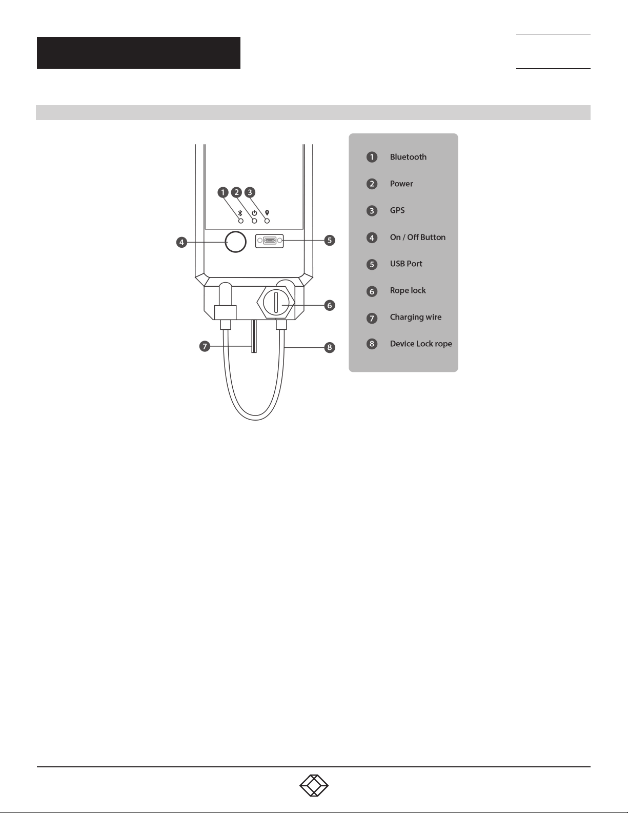
2.4 HARDWARE DESCRIPTION ...................................................................................................................................................................... 6
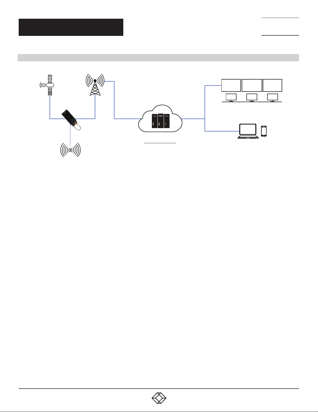
2.5 TYPICAL APPLICATION............................................................................................................................................................................ 7
3.1 CONFIGURATION VIA USB ......................................................................................................................................................... 8
3.1.1 OTA Configuration for Authorized Mobile Number.............................................................................................................................8
3.1.2 Configure APN .......................................................................................................................................................................................9
3.1.3 APN Configuration Request .................................................................................................................................................................9
3.1.4 Configure IP and Port..........................................................................................................................................................................10
3.1.5 GPRS (IP/Port) Configuration Request..............................................................................................................................................10
3.1.6 Set Data Transfer Interval ...................................................................................................................................................................11
3.1.7 Data Transfer Interval Request...........................................................................................................................................................12
3.1.8 Configure Train to Yard Time Interval................................................................................................................................................12
3.1.9 Set Train to Yard Time Interval Tequest.............................................................................................................................................13
3.1.10 Geo-Fence Configuration Request...................................................................................................................................................13
3.1.11 Authenticated Mobile Number Request ..........................................................................................................................................13
3.2 CONFIGURATION VIA SMS ...................................................................................................................................................... 14
3.2.1 OTA Configuration for Authorized Mobile Number..........................................................................................................................14
3.2.2 Configure APN ....................................................................................................................................................................................15
3.2.3 APN Configuration Request...............................................................................................................................................................15
3.2.4 Configure IP and Port .........................................................................................................................................................................16
3.2.5 GPRS (IP/Port) Configuration Request.............................................................................................................................................16
3.2.6 Set Data Transfer Interval...................................................................................................................................................................17
3.2.7 Data Transfer Interval Request ..........................................................................................................................................................18
3.2.8 Configure Train to Yard Time Interval ...............................................................................................................................................18
3.2.9 Set Train to Yard Time Interval Request............................................................................................................................................19
3.2.10 Geo-Fence Configuration Request ..................................................................................................................................................19
3.2.11 Authenticated Mobile Number Request..........................................................................................................................................19
3.2.12 Reboot Device....................................................................................................................................................................................20
3.2.13 Power Off Device...............................................................................................................................................................................20
3.3 CONFIGURATION VIA GPRS..................................................................................................................................................... 21
3.3.1 OTA Configuration for Authorized Mobile Number ..........................................................................................................................21
3.3.2 Configure APN.....................................................................................................................................................................................22
3.3.3 APN Configuration Request...............................................................................................................................................................22
3.3.4 Configure IP and Port .........................................................................................................................................................................23
3.3.5 GPRS (IP/Port) Configuration Request .............................................................................................................................................23
3.3.6 Set Data Transfer Interval...................................................................................................................................................................24
3.3.7 Data Transfer Interval Request ..........................................................................................................................................................25
3.3.8 Configure Train to Yard Time Interval ...............................................................................................................................................25
3.3.9 Set Train to Yard Time Interval Request............................................................................................................................................26
3.3.10 Geo-Fence Configuration Request ..................................................................................................................................................26

3
CHAPTER 1: HEADLINE
1. 8 7 7. 8 7 7. 2 2 6 9 BLACKBOX.COM
NEED HELP?
LE AVE THE TECH TO US
LIVE 24/7
TECHNICAL
SUPPORT
1. 8 7 7. 87 7. 2 2 6 9
3.3.11 Authenticated Mobile Number Request..........................................................................................................................................26
4.1 MODES........................................................................................................................................................................................ 27
4.2 MODE CHANGE PROCESS FLOW............................................................................................................................................. 27
4.3 MODE DESCRIPTION ................................................................................................................................................................ 27
6.1 CONNECT THE DEVICE WITH THE CONTAINER .................................................................................................................... 29
6.2 STEPS TO ACTIVATE THE DEVICE TO USE ............................................................................................................................ 30
7.1 DEVICE REGISTRATION IN THE JIDO WEB APPLICATION.................................................................................................... 31
7.2 TRACKING THE DEVICE ON A MAP IN A WEB APPLICATION .............................................................................................. 32
8.1 ANDROID APP TO TRACK JIDO................................................................................................................................................ 33
A.1 DISCLAIMER.............................................................................................................................................................................. 34
A.2 TRADEMARKS USED IN THIS MANUAL ................................................................................................................................. 34

41. 8 7 7. 8 7 7. 2 2 6 9 BLACKBOX.COM
NEED HELP?
LE AVE THE TECH TO US
LIVE 24/7
TECHNICAL
SUPPORT
1. 8 7 7. 87 7. 2 2 6 9
CHAPTER 1: SPECIFICATIONS
1. SPECIFICATIONS
SPECIFICATIONS (T63)
COMMUNICATION
GSM/GPRS DEFAULT Quad band (850, 900, 1800, 1900)
OPTIONAL MODEMS UMTS900/2100, UMTS850/1900
NUMBER OF SIMS Dual
ANTENNA TYPE Built-in
DATA CHANNELS SMS and TCP/IP
PROTOCOL Proprietary encrypted
LOCATION
TYPE GPS
TTFF 2 seconds (hot start)
POSITIONING ACCURACY 2.5 m CEP
VELOCITY ACCURACY 0.2 m/s
SUPPORT AGPS Yes
ANTENNA TYPE Built-in
BATTERY
TYPE Li ion rechargable
CAPACITY 15000 mAh
SENSORS
ON-BOARD Accelerometer
INPUT POWER
DUAL POWER 5 VDC from charger
24 VDC input from battery
LOCKING/UNLOCKING MECHANISM
MANUAL LOCK Manual key to lock/unlock, string attached
ENVIRONMENTAL
OPERATING TEMPERATURE -4 to +140° F (-20 to +60° C)
STORAGE TEMPERATURE -40 to +176° F (-40 to +80° C)
OPERATING HUMIDITY 5 to 95%, noncondensing
MECHANICAL
DIMENSIONS 8.26" H x 5.12" W x 1.77" D (21 x 13 x 4.5 cm)
WEIGHT Less than 1.76 lb. (800 g)
APPROVALS
PROTECTION RATING IP 67
CERTIFICATIONS CE, RoHS, IP67

5
1. 8 7 7. 8 7 7. 2 2 6 9 BLACKBOX.COM
NEED HELP?
LE AVE THE TECH TO US
LIVE 24/7
TECHNICAL
SUPPORT
1. 8 7 7. 87 7. 2 2 6 9
CHAPTER 2: OVERVIEW
2.1 INTRODUCTION
The JIDO GPS Freight Tracker with Manual Lock (T63) is used for transportation, logistics, shipment, and freight tracking.
It enhances end-to-end visibility of your assets and provides tampering alerts. This rugged device is weatherproof. Protected against
man and nature, JIDO is IP67 rated and features a hardened plastic, tamper-proof design.
Using the JIDO device, the user can get a complete picture of freight shipments from anywhere with internet access. JIDO provides
end -to-end visualization of shipments, and provides improved logistical tracking and improved security of valuable assets.
2.2 FEATURES
IP67 rated waterproof and dustproof. Constructed of hardened plastic. Tamperproof design.
Fast and easy installation. Simply attach JIDO with the lock and secure it on the magnetic mount.
End-to-end visualization. Visualize cargo shipment on a map with alerts for any deviations from its schedule.
Multiple sensors integration. Fast movement tilt lifting, door opening, lock opening and tampering, and temperature and humidity
Sufficient data backup. Store more than 3 months of location data when the shipment was out of network
Cargo safety: Alerts for any tampering, opening of lock, deviations from route, and unscheduled stops
Seamless connectivity. Dual SIM connects to any geography. Connect via Bluetooth to latch on to the router of the ship during deep
sea transport.
Create routes. Trips, geo-fences, stops, and zones provide intelligent reports.
Smooth tracking of device. Easy map-based system lets you track the device from the Web and a mobile app.
2.3 WHAT’S INCLUDED
Your package should include the following items. If anything is missing or damaged, contact Black Box Technical Support
at 877-877-2269 or info@blackbox.com.
(1) JIDO GPS Freight Tracker with Manual Lock
(1) 1-A charger
(1) data cable
(1) set of keys
(1) battery

61. 8 7 7. 8 7 7. 2 2 6 9 BLACKBOX.COM
NEED HELP?
LE AVE THE TECH TO US
LIVE 24/7
TECHNICAL
SUPPORT
1. 8 7 7. 87 7. 2 2 6 9
CHAPTER 2: OVERVIEW
2.4 HARDWARE DESCRIPTION
FIGURE 2-1. JIDO COMPONENTS

7
1. 8 7 7. 8 7 7. 2 2 6 9 BLACKBOX.COM
NEED HELP?
LE AVE THE TECH TO US
LIVE 24/7
TECHNICAL
SUPPORT
1. 8 7 7. 87 7. 2 2 6 9
CHAPTER 2: OVERVIEW
2.5 TYPICAL APPLICATION
NOC
Cloud Based Tracking
Server/Data Storage
24x7 Access to Data
External Sensor Data
GSM/GPRS
Container
Tracking System
Jido
Real-Time Monitoring
Container Location
Trip Management
Alerts
MIS Reports
Geo-Fencing
GPS
FIGURE 2-2. TYPICAL APPLICATION

81. 8 7 7. 8 7 7. 2 2 6 9 BLACKBOX.COM
NEED HELP?
LE AVE THE TECH TO US
LIVE 24/7
TECHNICAL
SUPPORT
1. 8 7 7. 87 7. 2 2 6 9
CHAPTER 3: DEVICE CONFIGURATIONS
3.1 CONFIGURATION VIA USB
3.1.1 OTA CONFIGURATION FOR AUTHORIZED MOBILE NUMBER
The user can program up to three mobile numbers from which the OTA configuration can be accepted. OTA Configuration
messages received from any numbers other than the entered numbers will be ignored. By default, this function is disabled,
but it can be enabled by sending an OTA message.
TABLE 3-1. OTA CONFIGURATION MESSAGES
SEQUENCE PARAMETER DATA DESCRIPTION REMARKS
1SOH *Header Always 1 byte
2Command ID 15 For status of device Always 2 bytes
3 Authorization status 1 or 0
Authorization status:
Enabled = 1
Disabled = 0
Always 1 byte
4Mobile number 919433236655 Mobile number
Disabled = 0 Varies 1 to 30 bytes
5EOH #Footer Always 1 byte
TABLE 3-2. MESSAGES TO/FROM DEVICE
MESSAGE TO DEVICE RETURN MESSAGE FROM DEVICE
EXAMPLE SUCCESS FAILURE
*15,0,0#(for Disabled) *12345678910101000,
15,0,1#
*12345678910101000,
15,0,0#
*15,1,919433236655#
*12345678910101000,
*12345678910101000,
15,1,1# ID
*12345678910101000,
15,1,1#
*15,1,+919433236655,+9194
33236657,+919
433236659#
*12345678910101000,
15,1,1#
*12345678910101000,
15,1,1#

9
1. 8 7 7. 8 7 7. 2 2 6 9 BLACKBOX.COM
NEED HELP?
LE AVE THE TECH TO US
LIVE 24/7
TECHNICAL
SUPPORT
1. 8 7 7. 87 7. 2 2 6 9
CHAPTER 3: DEVICE CONFIGURATIONS
3.1.2 CONFIGURE APN
TABLE 3-3. APN CONFIGURATION
SEQUENCE PARAMETER DATA DESCRIPTION REMARKS
1SOH *Header Always 1 byte
2Command ID 08 For APN Configuration
of Device Always 2 bytes
3APN1 airtelgprs.com APN e.g for Vodafone
-airtelgprs.com Always n byte
4Usr1 User1 User Name (Default : ) Always n byte
5pwd1 Password1 Password (Default : ) Always n byte
6APN2 Vodafonegprs.com APN e.g for Vodafone
- www Always n byte
7Usr2 User2 User Name (Default : ) Always n byte
8pwd2 Password2 Password (Default : ) Always n byte
9EOH #Footer Always 1 byte
TABLE 3-4. MESSAGES TO/FROM DEVICE
MESSAGE TO DEVICE RETURN MESSAGE FROM DEVICE
EXAMPLE SUCCESS FAILURE
*08,airtelgprs.com,,,www,,# *12345678910101000,08,1# *12345678910101000,08,0#
*Device ID,Command ID,status#
3.1.3 APN CONFIGURATION REQUEST
TABLE 3-5. APN MESSAGES TO/FROM DEVICE
MESSAGE TO DEVICE CONDITION REPLY FROM DEVICE
*08# Only APN *08,apn#
APN+usr+password *08,apn,usr,pswd#

10 1. 8 7 7. 8 7 7. 2 2 6 9 BLACKBOX.COM
NEED HELP?
LE AVE THE TECH TO US
LIVE 24/7
TECHNICAL
SUPPORT
1. 8 7 7. 87 7. 2 2 6 9
CHAPTER 3: DEVICE CONFIGURATIONS
3.1.4 CONFIGURE IP AND PORT
TABLE 3-6. IP AND PORT CONFIGURATION
SEQUENCE PARAMETER DATA DESCRIPTION REMARKS
1SOH *Header Always 1 byte
2Command ID 09 For IP & PORT
Configuration of Device Always 2 bytes
3 Primary Server IP 103.233.79.35 Primary Server IP where
data wiil sent Always n byte
4 Primary Server Port 8082 Primary Server Port
where data wiil sent Always n byte
5 Secondary server IP 103.233.79.36
Data will be sent to this
IP if Primary server is
not available
Always n byte
6 Secondary server Port 8081
Data will be sent to this
port if Primary server is
not available
Always n byte
7EOH #Footer Always 1 byte
TABLE 3-7. MESSAGES TO/FROM DEVICE
MESSAGE TO DEVICE RETURN MESSAGE FROM DEVICE
EXAMPLE SUCCESS FAILURE
*09,103.233.79.35,8082,103.233.79.36,
7001# *12345678910101000,09,1# *12345678910101000,09,0#
*Device ID,Command ID,status#
3.1.5 GPRS (IP/PORT) CONFIGURATION REQUEST
TABLE 3-8. GPRS (IP/PORT) MESSAGES TO/FROM DEVICE
MESSAGE TO DEVICE CONDITION REPLY FROM DEVICE
*09# Only Primary IP *09,prim_ip,prim_port#
Primary + Secondary ip *09,prim_ip,prim_port,sec_ip,sec_port#

11
1. 8 7 7. 8 7 7. 2 2 6 9 BLACKBOX.COM
NEED HELP?
LE AVE THE TECH TO US
LIVE 24/7
TECHNICAL
SUPPORT
1. 8 7 7. 87 7. 2 2 6 9
CHAPTER 3: DEVICE CONFIGURATIONS
3.1.6 SET DATA TRANSFER INTERVAL
TABLE 3-9. DATA TRANSFER INTERVAL CONFIGURATION
SEQUENCE PARAMETER DATA DESCRIPTION REMARKS
1SOH *Header Always 1 byte
2Command ID 10 For Time interval of location data in different mode Always 2 bytes
3Yard Mode YYard mode Always 1 byte
4 Battery Status (>upper level) 050 Battery Status for upper level in Yard Mode Always 3 bytes
5Time Interval 3600 Time interval in seconds for upper level of Battery Status
in Yard Mode
Varies from 1- 5
bytes
6Battery Status (>lower level -
<upper level) 020 Battery Status for > lower level to < upper level in Yard Mode Always 3 byte
7Time Interval 3000 Time interval in seconds for > lower level to < upper level
of Battery Status in Yard Mode
Varies from 1- 5
bytes
8 Battery Status (<low level) 020 Battery Status for < lower level in Yard Mode Always 3 byte
9Time Interval 7200 Time interval in seconds for < lower level of Battery Status
in Yard Mode
Varies from 1- 5
bytes
10 Truck Mode KTruck Mode Always 1 byte
11 Battery Status (>upper level) 060 Battery Status for upper level in Truck Mode Always 3 bytes
12 Time Interval 3350 Time interval in seconds for upper level of Battery Status
in Truck Mode
Varies from 1- 5
bytes
13 Battery Status (>lower level -
<upper level) 030 Battery Status for > lower level to < upper level in Truck Mode Always 3 bytes
14 Time Interval 3300 Time interval in seconds for > lower level to < upper level
of Battery Status in Truck Mode
Varies from 1- 5
bytes
15 Battery Status (<low level) 030 Battery Status for < lower level in Truck Mode Always 3 bytes
16 Time Interval 3200 Time interval in seconds for < lower level of Battery Status
in Truck Mode
Varies from 1- 5
bytes
17 Train Mode NTrain mode Always 1 byte
18 Battery Status (>upper level) 065 Battery Status for upper level in Train Mode Always 3 bytes
19 Time Interval 3150 Time interval in seconds for upper level of Battery Status
in Train Mode
Varies from 1- 5
bytes
20 Battery Status (>lower level -
<upper level) 030 Battery Status for > lower level to < upper level in Train Mode Always 3 bytes
21 Time Interval 3100 Time interval in seconds for > lower level to < upper level
of Battery Status in Train Mode
Varies from 1- 5
bytes
22 Battery Status (<low level) 030 Battery Status for < lower level in Train Mode Always 3 bytes
23 Time Interval 3000 Time interval in seconds for < lower level of Battery Status
in Train Mode
Varies from 1- 5
bytes
24 EOH #Footer Always 1 byte

12 1. 8 7 7. 8 7 7. 2 2 6 9 BLACKBOX.COM
NEED HELP?
LE AVE THE TECH TO US
LIVE 24/7
TECHNICAL
SUPPORT
1. 8 7 7. 87 7. 2 2 6 9
CHAPTER 3: DEVICE CONFIGURATIONS
TABLE 3-10. MESSAGES TO/FROM DEVICE
MESSAGE TO DEVICE RETURN MESSAGE FROM DEVICE
EXAMPLE SUCCESS FAILURE
*10,Y,050,3600,020,3000,020,720
0,K,060,3350,030,3300,030,3200
,N,065,3150,030,3100,030,3000#
*12345678910101000,10,1# *12345678910101000,10,0#
*Device ID,Command ID,status#
3.1.7 DATA TRANSFER INTERVAL REQUEST
TABLE 3-11. DATA TRANSFER INTERVAL REQUEST MESSAGE TO/FROM DEVICE
MESSAGE TO DEVICE CONDITION REPLY FRM DEVICE
*10#
*10,Y,Y_bat_up_level,Y_bat _up_interval,Y
_bat_low_level,Y_bat_medium_interval,Y_low_
level,Y_low_interval,K,K_bat_up_level,K_bat_
up_interval,K_bat_low_level,K_bat_medium_
interval,K_low_level,K_low_interval,N,N_bat_up_
level,N_bat_up_interval,N_bat_low_level,N_bat_
medium_interval,N_low_level,N_low_interval#
3.1.8 CONFIGURE TRAIN TO YARD TIME INTERVAL
TABLE 3-12. TRAIN TO YARD TIME INTERVAL CONFIGURATION
SEQUENCE PARAMETER DATA DESCRIPTION REMARKS
1SOH *Header Always 1 byte
2Command ID 11 For Time interval of Mode change data Always 2 bytes
3Time Interval 3600 Mode Change data sent in after 1 hr Varies from 1- 5 bytes
4EOH #Footer Always 1 byte
TABLE 3-13. MESSAGES TO/FROM DEVICE
MESSAGE TO DEVICE RETURN MESSAGE FROM DEVICE
EXAMPLE SUCCESS FAILURE
*11,3600# *12345678910101000,11,1# *12345678910101000,11,0#
*Device ID,Command ID,status#

13
1. 8 7 7. 8 7 7. 2 2 6 9 BLACKBOX.COM
NEED HELP?
LE AVE THE TECH TO US
LIVE 24/7
TECHNICAL
SUPPORT
1. 8 7 7. 87 7. 2 2 6 9
CHAPTER 3: DEVICE CONFIGURATIONS
3.1.9 SET TRAIN TO YARD TIME INTERVAL TEQUEST
TABLE 3-14. MESSAGES TO/FROM DEVICE
MESSAGE TO DEVICE CONDITION REPLY FROM DEVICE
*11# *11,interval#
3.1.10 GEO-FENCE CONFIGURATION REQUEST
TABLE 3-15. GEO-FENCE CONFIGURATION MESSAGES TO/FROM DEVICE
MESSAGE TO DEVICE CONDITION REPLY FROM DEVICE
*14# No Configuration *14,0#
1 Polygon *14,1,(long1 lat1,long2 lat2,long3 lat3,long4 lat4)#
1 Polygons *14,2,(long1 lat1,long2 lat2,long3 lat3,long4 lat4)(long1 lat1,long2 lat2,long3 lat3,long4 lat4)#
N Polygons (Max 10) *14,N,(long1 lat1,long2 lat2,long3 lat3,long4 lat4)(long1 lat1,long2 lat2,long3 lat3
long4 lat4)...(longN latN,longN latN,longN latN,longN latN)#
3.1.11 AUTHENTICATED MOBILE NUMBER REQUEST
TABLE 3-16. AUTHENTICATED MOBILE NUMBER MESSAGES TO/FROM DEVICE
MESSAGE TO DEVICE CONDITION REPLY FROM DEVICE
*15# No Configuration *15,0#
1 Number *15,1,num1#
2 Numbers *15,2,num1,num2#
3 Numbers *15,3,num1,num2,num3#

14 1. 8 7 7. 8 7 7. 2 2 6 9 BLACKBOX.COM
NEED HELP?
LE AVE THE TECH TO US
LIVE 24/7
TECHNICAL
SUPPORT
1. 8 7 7. 87 7. 2 2 6 9
CHAPTER 3: DEVICE CONFIGURATIONS
3.2 CONFIGURATION VIA SMS
3.2.1 OTA CONFIGURATION FOR AUTHORIZED MOBILE NUMBER
The user can program up to three mobile numbers from which the OTA configuration can be accepted. OTA Configuration
messages received from any numbers other than the entered numbers will be ignored. By default, this function is disabled,
but it can be enabled by sending an OTA message.
TABLE 3-17. OTA CONFIGURATION MESSAGES
SEQUENCE PARAMETER DATA DESCRIPTION REMARKS
1SOH *Header Always 1 byte
2Command ID 15 For status of device Always 2 bytes
3 Authorization status 1 or 0
Authorization status:
Enabled = 1
Disabled = 0
Always 1 byte
4Mobile number 919433236655 Mobile number
Disabled = 0 Varies 1 to 30 bytes
5EOH #Footer Always 1 byte
TABLE 3-18. MESSAGES TO/FROM DEVICE
MESSAGE TO DEVICE RETURN MESSAGE FROM DEVICE
EXAMPLE SUCCESS FAILURE
*15,0,0#(for Disabled) *12345678910101000,
15,0,1#
*12345678910101000,
15,0,0#
*15,1,919433236655#
*12345678910101000,
*12345678910101000,
15,1,1# ID
*12345678910101000,
15,1,1#
*15,1,+919433236655,+9194
33236657,+919
433236659#
*12345678910101000,
15,1,1#
*12345678910101000,
15,1,1#

15
1. 8 7 7. 8 7 7. 2 2 6 9 BLACKBOX.COM
NEED HELP?
LE AVE THE TECH TO US
LIVE 24/7
TECHNICAL
SUPPORT
1. 8 7 7. 87 7. 2 2 6 9
CHAPTER 3: DEVICE CONFIGURATIONS
3.2.2 CONFIGURE APN
TABLE 3-19. APN CONFIGURATION
SEQUENCE PARAMETER DATA DESCRIPTION REMARKS
1SOH *Header Always 1 byte
2Command ID 08 For APN Configuration
of Device Always 2 bytes
3APN1 airtelgprs.com APN e.g for Vodafone
-airtelgprs.com Always n byte
4Usr1 User1 User Name (Default : ) Always n byte
5pwd1 Password1 Password (Default : ) Always n byte
6APN2 Vodafonegprs.com APN e.g for Vodafone
- www Always n byte
7Usr2 User2 User Name (Default : ) Always n byte
8pwd2 Password2 Password (Default : ) Always n byte
9EOH #Footer Always 1 byte
TABLE 3-20. MESSAGES TO/FROM DEVICE
MESSAGE TO DEVICE RETURN MESSAGE FROM DEVICE
EXAMPLE SUCCESS FAILURE
*08,airtelgprs.com,,,www,,# *12345678910101000,08,1# *12345678910101000,08,0#
*Device ID,Command ID,status#
3.2.3 APN CONFIGURATION REQUEST
TABLE 3-21. APN MESSAGES TO/FROM DEVICE
MESSAGE TO DEVICE CONDITION REPLY FROM DEVICE
*08# Only APN *08,apn#
APN+usr+password *08,apn,usr,pswd#

16 1. 8 7 7. 8 7 7. 2 2 6 9 BLACKBOX.COM
NEED HELP?
LE AVE THE TECH TO US
LIVE 24/7
TECHNICAL
SUPPORT
1. 8 7 7. 87 7. 2 2 6 9
CHAPTER 3: DEVICE CONFIGURATIONS
3.2.4 CONFIGURE IP AND PORT
TABLE 3-22. IP AND PORT CONFIGURATION
SEQUENCE PARAMETER DATA DESCRIPTION REMARKS
1SOH *Header Always 1 byte
2Command ID 09 For IP & PORT
Configuration of Device Always 2 bytes
3 Primary Server IP 103.233.79.35 Primary Server IP where
data wiil sent Always n byte
4 Primary Server Port 8082 Primary Server Port
where data wiil sent Always n byte
5 Secondary server IP 103.233.79.36
Data will be sent to this
IP if Primary server is
not available
Always n byte
6 Secondary server Port 8081
Data will be sent to this
port if Primary server is
not available
Always n byte
7EOH #Footer Always 1 byte
TABLE 3-23. MESSAGES TO/FROM DEVICE
MESSAGE TO DEVICE RETURN MESSAGE FROM DEVICE
EXAMPLE SUCCESS FAILURE
*09,103.233.79.35,8082,103.233.79.36,
7001# *12345678910101000,09,1# *12345678910101000,09,0#
*Device ID,Command ID,status#
3.2.5 GPRS (IP/PORT) CONFIGURATION REQUEST
TABLE 3-24. GPRS (IP/PORT) MESSAGES TO/FROM DEVICE
MESSAGE TO DEVICE CONDITION REPLY FROM DEVICE
*09# Only Primary IP *09,prim_ip,prim_port#
Primary + Secondary ip *09,prim_ip,prim_port,sec_ip,sec_port#

17
1. 8 7 7. 8 7 7. 2 2 6 9 BLACKBOX.COM
NEED HELP?
LE AVE THE TECH TO US
LIVE 24/7
TECHNICAL
SUPPORT
1. 8 7 7. 87 7. 2 2 6 9
CHAPTER 3: DEVICE CONFIGURATIONS
3.2.6 SET DATA TRANSFER INTERVAL
TABLE 3-25. DATA TRANSFER INTERVAL CONFIGURATION
SEQUENCE PARAMETER DATA DESCRIPTION REMARKS
1SOH *Header Always 1 byte
2Command ID 10 For Time interval of location data in different mode Always 2 bytes
3Yard Mode YYard mode Always 1 byte
4 Battery Status (>upper level) 050 Battery Status for upper level in Yard Mode Always 3 bytes
5Time Interval 3600 Time interval in seconds for upper level of Battery Status
in Yard Mode
Varies from 1- 5
bytes
6Battery Status (>lower level -
<upper level) 020 Battery Status for > lower level to < upper level in Yard Mode Always 3 byte
7Time Interval 3000 Time interval in seconds for > lower level to < upper level
of Battery Status in Yard Mode
Varies from 1- 5
bytes
8 Battery Status (<low level) 020 Battery Status for < lower level in Yard Mode Always 3 byte
9Time Interval 7200 Time interval in seconds for < lower level of Battery Status
in Yard Mode
Varies from 1- 5
bytes
10 Truck Mode KTruck Mode Always 1 byte
11 Battery Status (>upper level) 060 Battery Status for upper level in Truck Mode Always 3 bytes
12 Time Interval 3350 Time interval in seconds for upper level of Battery Status
in Truck Mode
Varies from 1- 5
bytes
13 Battery Status (>lower level -
<upper level) 030 Battery Status for > lower level to < upper level in Truck Mode Always 3 bytes
14 Time Interval 3300 Time interval in seconds for > lower level to < upper level
of Battery Status in Truck Mode
Varies from 1- 5
bytes
15 Battery Status (<low level) 030 Battery Status for < lower level in Truck Mode Always 3 bytes
16 Time Interval 3200 Time interval in seconds for < lower level of Battery Status
in Truck Mode
Varies from 1- 5
bytes
17 Train Mode NTrain mode Always 1 byte
18 Battery Status (>upper level) 065 Battery Status for upper level in Train Mode Always 3 bytes
19 Time Interval 3150 Time interval in seconds for upper level of Battery Status
in Train Mode
Varies from 1- 5
bytes
20 Battery Status (>lower level -
<upper level) 030 Battery Status for > lower level to < upper level in Train Mode Always 3 bytes
21 Time Interval 3100 Time interval in seconds for > lower level to < upper level
of Battery Status in Train Mode
Varies from 1- 5
bytes
22 Battery Status (<low level) 030 Battery Status for < lower level in Train Mode Always 3 bytes
23 Time Interval 3000 Time interval in seconds for < lower level of Battery Status
in Train Mode
Varies from 1- 5
bytes
24 EOH #Footer Always 1 byte

18 1. 8 7 7. 8 7 7. 2 2 6 9 BLACKBOX.COM
NEED HELP?
LE AVE THE TECH TO US
LIVE 24/7
TECHNICAL
SUPPORT
1. 8 7 7. 87 7. 2 2 6 9
CHAPTER 3: DEVICE CONFIGURATIONS
TABLE 3-26. MESSAGES TO/FROM DEVICE
MESSAGE TO DEVICE RETURN MESSAGE FROM DEVICE
EXAMPLE SUCCESS FAILURE
*10,Y,050,3600,020,3000,020,720
0,K,060,3350,030,3300,030,3200
,N,065,3150,030,3100,030,3000#
*12345678910101000,10,1# *12345678910101000,10,0#
*Device ID,Command ID,status#
3.2.7 DATA TRANSFER INTERVAL REQUEST
TABLE 3-27. DATA TRANSFER INTERVAL REQUEST MESSAGE TO/FROM DEVICE
MESSAGE TO DEVICE CONDITION REPLY FRM DEVICE
*10#
*10,Y,Y_bat_up_level,Y_bat _up_interval,Y
_bat_low_level,Y_bat_medium_interval,Y_low_
level,Y_low_interval,K,K_bat_up_level,K_bat_
up_interval,K_bat_low_level,K_bat_medium_
interval,K_low_level,K_low_interval,N,N_bat_up_
level,N_bat_up_interval,N_bat_low_level,N_bat_
medium_interval,N_low_level,N_low_interval#
3.2.8 CONFIGURE TRAIN TO YARD TIME INTERVAL
TABLE 3-28. TRAIN TO YARD TIME INTERVAL CONFIGURATION
SEQUENCE PARAMETER DATA DESCRIPTION REMARKS
1SOH *Header Always 1 byte
2Command ID 11 For Time interval of Mode change data Always 2 bytes
3Time Interval 3600 Mode Change data sent in after 1 hr Varies from 1- 5 bytes
4EOH #Footer Always 1 byte
TABLE 3-29. MESSAGES TO/FROM DEVICE
MESSAGE TO DEVICE RETURN MESSAGE FROM DEVICE
EXAMPLE SUCCESS FAILURE
*11,3600# *12345678910101000,11,1# *12345678910101000,11,0#
*Device ID,Command ID,status#

19
1. 8 7 7. 8 7 7. 2 2 6 9 BLACKBOX.COM
NEED HELP?
LE AVE THE TECH TO US
LIVE 24/7
TECHNICAL
SUPPORT
1. 8 7 7. 87 7. 2 2 6 9
CHAPTER 3: DEVICE CONFIGURATIONS
3.2.9 SET TRAIN TO YARD TIME INTERVAL REQUEST
TABLE 3-30. MESSAGES TO/FROM DEVICE
MESSAGE TO DEVICE CONDITION REPLY FROM DEVICE
*11# *11,interval#
3.2.10 GEO-FENCE CONFIGURATION REQUEST
TABLE 3-31. GEO-FENCE CONFIGURATION MESSAGES TO/FROM DEVICE
MESSAGE TO DEVICE CONDITION REPLY FROM DEVICE
*14# No Configuration *14,0#
1 Polygon *14,1,(long1 lat1,long2 lat2,long3 lat3,long4 lat4)#
1 Polygons *14,2,(long1 lat1,long2 lat2,long3 lat3,long4 lat4)(long1 lat1,long2 lat2,long3 lat3,long4 lat4)#
N Polygons (Max 10) *14,N,(long1 lat1,long2 lat2,long3 lat3,long4 lat4)(long1 lat1,long2 lat2,long3 lat3
long4 lat4)...(longN latN,longN latN,longN latN,longN latN)#
3.2.11 AUTHENTICATED MOBILE NUMBER REQUEST
TABLE 3-32. AUTHENTICATED MOBILE NUMBER MESSAGES TO/FROM DEVICE
MESSAGE TO DEVICE CONDITION REPLY FROM DEVICE
*15# No Configuration *15,0#
1 Number *15,1,num1#
2 Numbers *15,2,num1,num2#
3 Numbers *15,3,num1,num2,num3#

20 1. 8 7 7. 8 7 7. 2 2 6 9 BLACKBOX.COM
NEED HELP?
LE AVE THE TECH TO US
LIVE 24/7
TECHNICAL
SUPPORT
1. 8 7 7. 87 7. 2 2 6 9
CHAPTER 3: DEVICE CONFIGURATIONS
3.2.12 REBOOT DEVICE
TABLE 3-32. REBOOT DEVICE CONFIGURATION
SEQUENCE PARAMETER DATA DESCRIPTION REMARKS
1SOH *Header Always 1 byte
2Command ID 13 For Status of Device Always 2 bytes
3 Reboot reboot Reboot the device reboot (Fixed) Always 6 bytes
4EOH #Footer Always 1 byte
TABLE 3-33. MESSAGES TO/FROM DEVICE
MESSAGE TO DEVICE RETURN MESSAGE FROM DEVICE
EXAMPLE SUCCESS FAILURE
*13,reboot# Reboot Successful Reboot Failed
*Device ID,Command ID,status#
3.2.13 POWER OFF DEVICE
TABLE 3-34. POWER OFF DEVICE CONFIGURATION
SEQUENCE PARAMETER DATA DESCRIPTION REMARKS
1SOH *Header Always 1 byte
2Command ID 17 For Status of Device Always 2 bytes
3Power off off Power OFF Always 3 bytes
4EOH #Footer Always 1 byte
TABLE 3-35. MESSAGES TO/FROM DEVICE
MESSAGE TO DEVICE RETURN MESSAGE FROM DEVICE
EXAMPLE SUCCESS FAILURE
*17,off# POWER OFF Successful POWER OFF Failed
*Device ID,Command ID,status#
Table of contents
Other Black Box GPS manuals