TABLE OF CONTENTS
2
Table of Contents........................................... 2
Introduction................................................... 3
Safety Definitions .......................................... 3
Important safety instructions ....................... 4
Fuel Safety .........................................................6
Safety and Dataplate Labels.......................................7
Safety Symbols.....................................................8
Operation Symbols ............................................... 10
Quick Start Label Symbols....................................... 10
Controls and Features ................................. 11
Parts Included .................................................... 12
Assembly ..................................................... 13
Remove the Water Pump from the Shipping Carton ............ 13
Install Wheels and Support Legs ................................ 13
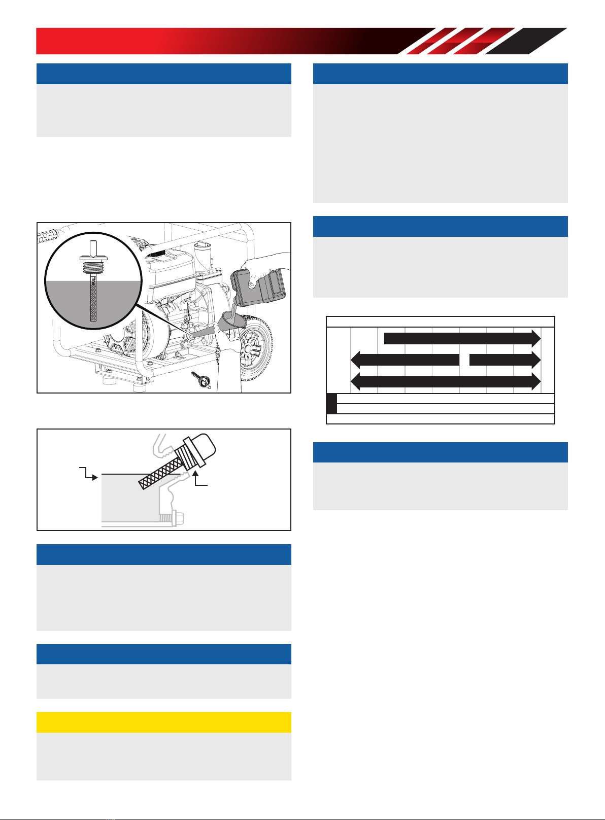
Add Engine Oil.................................................... 13
Add Fuel .......................................................... 14
Operation..................................................... 16
Water Pump Location ............................................ 16
Connecting a Hose Kit ........................................... 16
Priming the Pump ................................................ 20
Before Starting the Engine....................................... 21
Starting the Engine............................................... 21
Stopping the Engine.............................................. 22
Operation at High Altitude ....................................... 23
Maintenance ................................................ 24
Cleaning the Water Pump ........................................ 24
Changing the Engine Oil ......................................... 24
Cleaning and Adjusting the Spark Plug(s) ....................... 24
Cleaning the Air Filter ............................................ 25
Cleaning the Spark Arrestor ..................................... 25
Adjusting the Governor........................................... 26
Maintenance Schedule........................................... 26
Storage ........................................................ 27
Water Pump Storage ............................................. 27
Short Term Engine Storage (Up to 30 Days) .................... 27
Mid Term Engine Storage ( 30 Days – 1 year) .................. 27
Long Term Storage............................................... 27
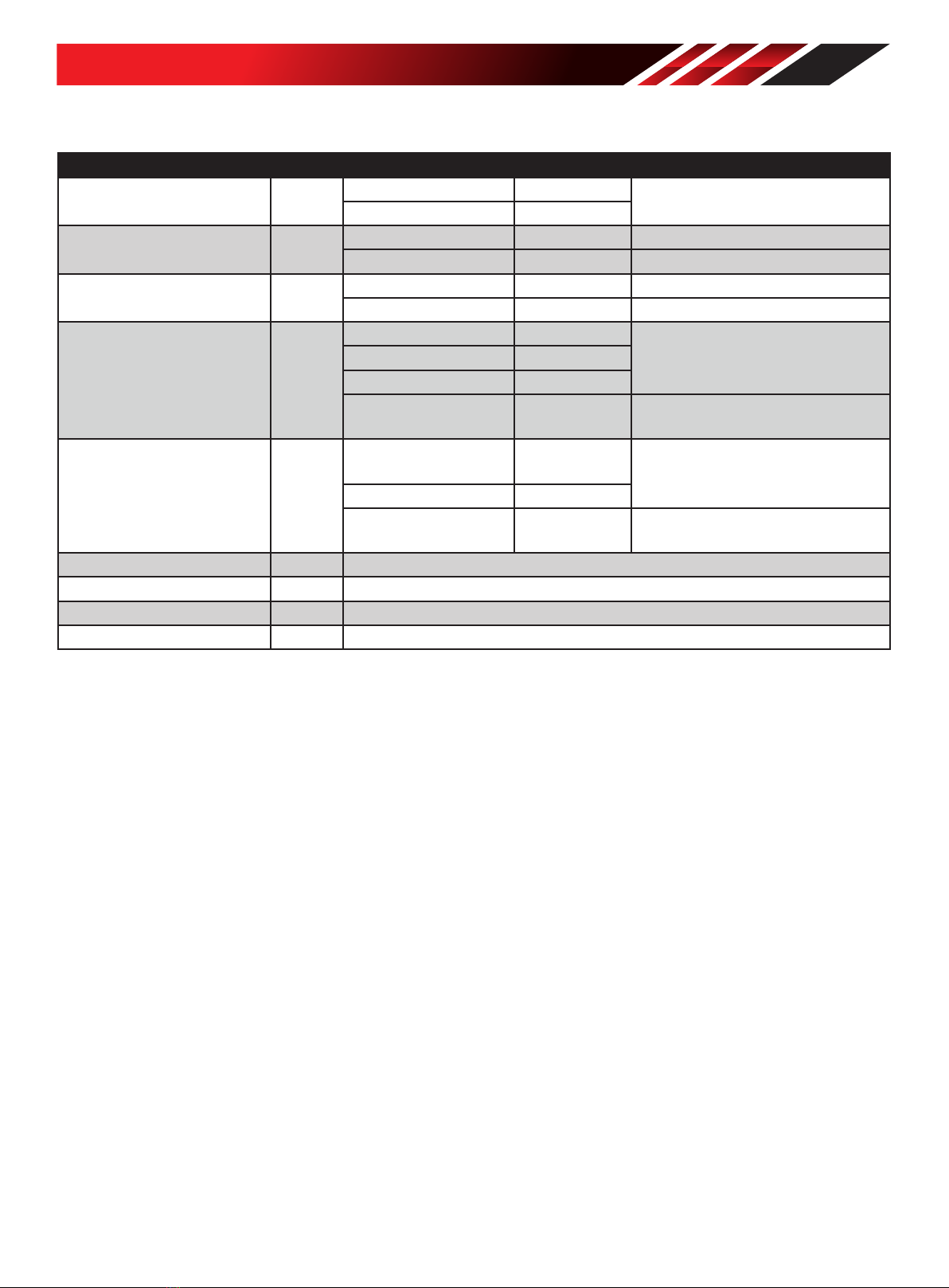
Specifications.............................................. 29
Water Pump Specifications ...................................... 29
Engine Specifications ............................................ 29
Spark Plug Specifications........................................ 29
Valve Specifications.............................................. 29
Engine Oil Specifications......................................... 29
Fuel Specifications ............................................... 29
Temperature Specifications...................................... 29
Troubleshooting........................................... 30
Warranty...................................................... 32
Warranty Qualifications .......................................... 32
Repair/Replacement Warranty................................... 32
Do Not Return The Unit To The Place Of Purchase ............. 32
Warranty Exclusions ............................................. 32
Other Exclusions ................................................. 32
Limits of Implied Warranty and Consequential Damage........ 32
Contact Information .............................................. 32