black forest motion PINE Series User manual

Black Forest Motion GmbH
Waldstraße 2
78136 Schonach
Page 1of 114
Black Forest Motion ▪PINE Controller User Manual
www.blackforestmotion.com ▪[email protected]
PINE Motion Controller
User Manual
Valid for: PINE, PINE LITE, PINE R
Firmware Version: 1.5
Release Date: 6. June 2019
Revision: 1

Black Forest Motion GmbH
Waldstraße 2
78136 Schonach
Page 2of 114
Black Forest Motion ▪PINE Controller User Manual
www.blackforestmotion.com ▪[email protected]
Dear customer,
Thank you for purchasing the PINE Motion Controller from Black Forest Motion.
As our customer, you receive our highest attention and we are always there for
you, if you have questions or suggestions to our products.
In order to make it as easy as possible for you to start using our product, please
read this user manual carefully and familiarize yourself with its safe and efficient
operation.
Keep this user manual in a safe place so that it can be accessed at any time if
necessary.
The current user manual is also always available for download from our website:
https://www.blackforestmotion.com/support
Company Address:
Black Forest Motion GmbH
Waldstraße 2
D-78136 Schonach im Schwarzwald
Tel.: +49 (0) 7722 920203
E-Mail: [email protected]
https://blackforestmotion.com
Register Court: County Court Freiburg im Breisgau
Register Number: HRB 717974
CEO: Moritz Huber, Patrick Ketterer

Black Forest Motion GmbH
Waldstraße 2
78136 Schonach
Page 3of 114
Black Forest Motion ▪PINE Controller User Manual
www.blackforestmotion.com ▪[email protected]
Content
1. Usage of this Manual............................................................................................ 5
2. Preface ................................................................................................................... 6
3. Introduction............................................................................................................ 7
4. Safety Instructions ................................................................................................. 8
5. Technical Specifications .................................................................................... 10
6. Connections ........................................................................................................ 11
6.1. Difference between the PINE Models ....................................................... 11
6.2. Motors ............................................................................................................. 11
6.2.1. Compatible 3rd Party Manufacturers.................................................. 11
6.2.2. Motor Connector Pinout ....................................................................... 12
6.3. Cameras......................................................................................................... 12
6.3.1. Technical Details of the Camera Ports ............................................... 14
6.4. AUX Input ....................................................................................................... 14
6.4.1. Technical Details of the AUX Input ...................................................... 15
6.5. Power Supply of the Controller................................................................... 16
6.6. Mounting Options ......................................................................................... 16
7. Operation of the Controller............................................................................... 17
7.1. Boot-Up Process ............................................................................................ 17
8. PINE Motion App ................................................................................................. 18
8.1. Connection with a PINE Controller ............................................................ 18
8.2. Motor Profiles / Motor Quick Setup ............................................................ 20
8.3. Motor Setup Assistant ................................................................................... 22
8.4. Status Bar........................................................................................................ 24
8.5. Homescreen .................................................................................................. 24
8.6. Motor Settings................................................................................................ 25
8.7. Connections .................................................................................................. 29
8.8. Freerun............................................................................................................ 31

Black Forest Motion GmbH
Waldstraße 2
78136 Schonach
Page 4of 114
Black Forest Motion ▪PINE Controller User Manual
www.blackforestmotion.com ▪[email protected]
8.9. Application Modes....................................................................................... 33
8.9.1. General Screen Layout......................................................................... 33
8.9.2. Time-Lapse .............................................................................................. 35
8.9.3. Video........................................................................................................ 46
8.9.4. Giga-Pixel ................................................................................................ 50
8.9.5. 3D-Scan ................................................................................................... 62
8.9.6. 360-Degree ............................................................................................. 73
8.9.7. Live ........................................................................................................... 87
8.9.8. Turntable.................................................................................................. 91
8.9.9. Astro ......................................................................................................... 92
8.9.10. Intervalometer..................................................................................... 94
8.10. Multitasking................................................................................................. 97
9. Firmware Updates............................................................................................... 98
9.1. Activating the Firmware Update Mode on PINE ..................................... 98
9.2. Updating on Windows................................................................................ 100
9.3. Updating on Mac OS X..............................................................................102
10. Troubleshooting and FAQs............................................................................105
11.Index................................................................................................................. 110
Black Forest Motion GmbH
Waldstraße 2
78136 Schonach
Page 5of 114
Black Forest Motion ▪PINE Controller User Manual
www.blackforestmotion.com ▪[email protected]
1. Usage of this Manual
This manual serves as a help and reference document for the end user of the
Black Forest Motion PINE Controller. Read this manual thoroughly to familiarize
yourself with the function of the device.
In this manual different info fields are used to clarify important points for the
reader. These are listed below.
Important Note
Tip
This is an important hint. Please observe it to avoid unexpected
behavior of the device.
This is a useful tip that will be helpful when using the device.

Black Forest Motion GmbH
Waldstraße 2
78136 Schonach
Page 6of 114
Black Forest Motion ▪PINE Controller User Manual
www.blackforestmotion.com ▪[email protected]
2. Preface
This work is protected by copyright. The rights based thereby, in particular those
of the translation, the reprint, the lecture, the removal of illustrations or tables,
the radio transmission, the microfilming or the duplication on other ways and
the storage in data processing plants, remain reserved, also with only partial
utilization.
The trademarks and brand names used in this book are the property of their
respective owners.
All contents, illustrations, graphics were created with the greatest care. The
author accepts no liability for any damage, in particular personal injury or
damage to property, which may result from the use of this book.
Unless otherwise indicated, photos and illustrations are the property of the
author.

Black Forest Motion GmbH
Waldstraße 2
78136 Schonach
Page 7of 114
Black Forest Motion ▪PINE Controller User Manual
www.blackforestmotion.com ▪[email protected]
3. Introduction
PINE, PINE LITE and PINE R are the most universal and flexible motion controllers
on the market.
PINE is a universal and smartphone-controlled device for motion-controlled
photography and video applications. With PINE you can create automated
camera movements, panoramic Giga-pixel and 360° photos, motion-
controlled time-lapse, automated 3D photogrammetry scans and more.
Universal and flexible
PINE is widely compatible with existing hardware such as sliders, pan/tilt
heads and focusing units. Control up to 4 axes and 2 cameras
simultaneously with one controller. Corresponding adapter cables to
third-party systems are available from Black Forest Motion.
Smartphone-Control
The most convenient way to control your system. Simply use your
smartphone or tablet and the PINE Motion App gives you access to the
extensive functions of the PINE Controller.
Once you've set everything up, the PINE Controller ends its task even if
the connection to the app is disconnected or your phone's battery dies.
The PINE Motion App is available for Android and iOS devices.
High-quality Connectors & Cables
PINE uses high quality, lockable Hirose connectors for a secure connection
to the motors. The camera and power connections are equipped with
industry standard connectors.

Black Forest Motion GmbH
Waldstraße 2
78136 Schonach
Page 8of 114
Black Forest Motion ▪PINE Controller User Manual
www.blackforestmotion.com ▪[email protected]
4. Safety Instructions
a) Before operating the device, make sure that you only use cables and
accessories manufactured or recommended by us.
b) Never connect or disconnect a motor connection to the controller while
it is in operation. Disconnect the power supply to the PINE Controller
before connecting or disconnecting motors. Otherwise the motors or the
controller as well as all connected devices may be damaged!
c) Never use the controller in humid or wet environments such as rain. Water
and moisture entering the controller may destroy it, cause unexpected
behavior, or cause personal injury from electric shock.
d) With the PINE Controller you can control stepper motors. These stepper
motors can generate a very high force, especially if they are geared. It
is your responsibility as a user to ensure that no persons are injured, or
other damage is caused during operation.
e) Before the motors are connected to the PINE Controller, all motors should
be mechanically brought into a position where they can move freely.
f) PINE has no sensors to detect the current position of the motors. It may
happen that a motor is mechanically blocked (e.g. if it is overloaded or
blocked) and does not continue to rotate. In this case, the stored
positions no longer correspond to the current positions of the Motion
Control. If a stored sequence is then played back, the movement can
be completely different from the movement programmed by the user.
In the worst case, this can lead to defects in the attached accessories,
cables or even injuries.
g) If the device and the connected motors behave differently than
expected, please disconnect the power supply at the PINE Controller
immediately to stop the movement.
h) Do not reset the PINE controller into firmware update mode without
intending to install a new firmware. The controller cannot be used in
update mode until a new firmware has been installed.

Black Forest Motion GmbH
Waldstraße 2
78136 Schonach
Page 9of 114
Black Forest Motion ▪PINE Controller User Manual
www.blackforestmotion.com ▪[email protected]
The symbol of a crossed-out wheeled bin indicates that our
device complies with the Directive 2012/19/EU of the
European Parliament and European Council of 27.01.2003
on the separate collection of electrical and electronic
equipment.
By affixing the CE mark, we declare that our device, in
accordance with EU Regulation 765/2008, meets the
applicable requirements laid down in the Community
harmonization legislation on its affixing.
Black Forest Motion GmbH
Waldstraße 2
78136 Schonach
Page 10 of 114
Black Forest Motion ▪PINE Controller User Manual
www.blackforestmotion.com ▪[email protected]
5. Technical Specifications
PINE
PINE LITE
PINE R
Operating Temperature
-20° to +45°
Storage Temperature
-30° to +60°
Humidity
10%-90% not condensing
Connectors
Power: DC-Barrel 2.1x5.5mm Center Positive
USB: Micro USB B
Motors: Hirose HR10A-7R-6S(73)
(6-pin Female)
4x
2x
4x
Cameras: 2.5mm TRS 3-pin
2x
1x
1x
AUX: 2.5mm TRS 3-pin
1x
1x
1x
Expansion RJ11 6-pin
2x
0x
0x
Limitswitch
Mechanical (NC) Switch for each Motor (Pin 5 and Pin 6 on the
HR10 Connectors)
Motor Type
Bipolar Stepper motors (max. 1.2A per Chanel)
Motor Ports
Not limited with Expansion
4x
2x
4x
Expansion
Daisy Chain over Bluetooth or
RJ11
Yes
No
No
Input-voltage
10-24V
Dimensions
L/W/H: 99 x 77 x 30mm
Weight
Approx. 150g
App Compatibility
Android 4.3 or newer / iPhone 5 and iOS 10.3 or newer
Wireless Range
30-100m under ideal conditions and line of sight
Wireless Technology
Bluetooth Low Energy 4.1 (2.4-2.48 GHz)
CPU
ARM Cortex
Firmware Update
Over Micro USB (With PINE Firmware Updater Utility)
All PINE controllers were subjected to the following test specifications, which
were successfully passed:
•Radio interference voltage mains
connection EN 61000-6-3:2007+A1:2011
•Radio interference field strength EN 61000-6-3:2007+A1:2011
•ESD-Test EN 61000-4-2:2009
•Testing against electromagnetic fields EN 61000-4-3:2006+A1:2008+A2:2010
•Burst-Test EN 61000-4-4:2012
•Surge-Test EN 61000-4-5:2014
•Testing against conducted radio
interference EN 61000-4-6:2014
•Testing against magnetic fields with
energy frequencies EN 61000-4-11:2004

Black Forest Motion GmbH
Waldstraße 2
78136 Schonach
Page 11 of 114
Black Forest Motion ▪PINE Controller User Manual
www.blackforestmotion.com ▪[email protected]
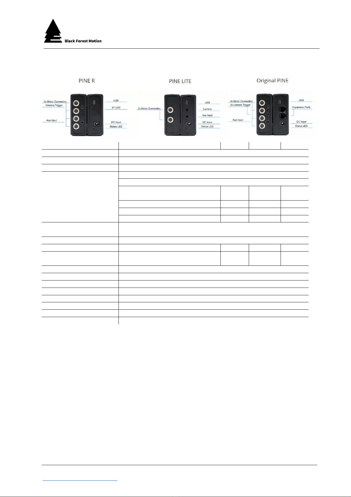
6. Connections
The PINE models have different connectors configurations. They differ in the
number of motor and camera connections as well as the serial RJ11 sockets.
6.1. Difference between the PINE Models
PINE
PINE LITE
PINE R
Number of Motor Ports
4
2
4
Number of Camera Ports
2
1
1
Number of AUX Ports
1
1
1
Wireless expandable
Yes
Only with PINE
Only with PINE
Wired expandable
Yes
No
No
6.2. Motors
Only stepper motors may be connected to the motor sockets. The
connection is made via a lockable high-quality Hirose HR10 socket.
The motors available via Black Forest Motion offer the same high-quality
connectors and can be connected with the standard Black Forest Motion
4pin Hirose cables.
In addition, the PINE controllers support various third-party motor units. These
are listed in the following chapter.
6.2.1. Compatible 3rd Party Manufacturers
Any motorized slider, pan/tilt head, turntable, focus/zoom unit that has a
stepper motor can be connected to PINE. Here are some examples of
working systems:
–Dynamic Perception Stage Zero Slider
–Dynamic Perception Stage One Slider
–Dynamic Perception Sapphire Pro Pan + Tilt Head
–Dynamic Perception Stage R Rotary System
–MDK V5 Pan & Tilt Head
–MDK V6 Pan & Tilt Head
–Rhino Motion Slider
–PocketSlider PT PRO
–PT Pan Tilt Head (PocketSlider)
–Nic-O-Slider

Black Forest Motion GmbH
Waldstraße 2
78136 Schonach
Page 12 of 114
Black Forest Motion ▪PINE Controller User Manual
www.blackforestmotion.com ▪[email protected]
–Nic-O-Tilt Head
–eMotimo Turntable
–PureMoCo Focus/Zoom Unit
–GVM Slider
–Many more
6.2.2. Motor Connector Pinout
The following connection diagram is given for the proper use of your own
stepper motors.
Connections 5 and 6 can be used for mechanical limit switches (normally
closed). If the contacts are opened, the PINE controller can detect the
start positions of the motors (if activated in the app).
6.3. Cameras
All cameras that can be triggered with a so-called "trigger cable" can be
connected. Cables from other manufacturers can also be used. On the
controller side, these cables must have a 2.5mm 3-pin TRS plug.
The following cables, which are compatible with the specified cameras, are
available as accessories (see following page):
Never disconnect motors from the PINE Controller while
it is powered on. Never plug motors into the controller
while it is active. This can lead to defects of the internal
motor drivers. Always disconnect the power supply
before connecting and disconnecting motors.

Black Forest Motion GmbH
Waldstraße 2
78136 Schonach
Page 13 of 114
Black Forest Motion ▪PINE Controller User Manual
www.blackforestmotion.com ▪[email protected]
Type
Camera
E3
For Canon:
G10/G11/G12/G15/G1X/G1X
II/T1i/T2i/T3i/T3/T4i/T5i/450D/500D/550D/600D/650D/700D/70D/750D
/760D/800D/80D/100D/60D/77D/M6/M5/400D/350D/300D/1300D/1
200D/1100D/1000D/SX50/SX60
N3
For Canon:
7D/7DII/6D/50D/5DII/5DIII/5D/5D4/5DS/40D/30D/20D/10D/1D/1DS/
1DX/
1Ds Mark II/1Ds Mark III/1Ds Mark IV/EOS-1V/EOS-3
DC0
For Nikon:
D1/D1H/D1X/D2/D2H/D2X/D3/D3s/D3x/D4/D5/D100/D200/D300/D
300s/D500/D700/
D800 /D800e/D810/F100/F90/F90X/N90s/F6/F5
For Fujifilm: S3 Pro/S5 Pro
For Kodak: DCS-14N
DC2
For Nikon:
D7500/D750/D7200/D7100/D7000/D610/D600/D5600/D5500/D5300/
D5200/D5100/
D5000/D3300/D3200/D3100/D90/DF/P7700/P7800/coolpix A
S1
For Sony:
a900/a850/a800/a700/a580/a560/a550/a500/a450/a400/a350/a3
00/a200/a100/
a99/ a77/a65/ a57/a55/a35/a33/a77M2/a99M2
For Konica Minolta: DIMAGE a2/a1/9/7Hi/7i/7/5/4/3/DYNAX 7D/5D
S2
For Sony:
a9/a7/a7R/a7S/a7SII/a7R
II/a6500/a6300/a6000/a5100/a5000/a3000/HX300/HX50/
HX60/RX100 II/RX100 III/RX100M4/RX100M5/a58/NEX-3N
L1
For Panasonic DMC:
FZ50/FZ50K/FZ50S/FZ30/FZ30K/FZ20/FZ20K/FZ20S/FZ300/FZ200/FZ150/
FZ100/FZ1000/FZ2000/FZ2500/G85H/G85/G10/G7/G6/G5/G3/G2/G
1/GH4A/GH4/GX8/GX7/GX1/GH3/GH2/GH1/GF1/LC-1/L1/L10/DC-
GH5
For Leica: DIGILUX2/DIGILUX3
UC1
For Olympus:
E-620/E-600/E-550/E-520/E-510/E-450/E-420/E-410/E-100/E-30/E-
M10/E-M10II/E-M5/E-M5II/E-M1/E-PM1/E-PM2/PEN-F/E-PL8/E-PL7/E-
PL6/E-PL5/E-PL3/E-PL2/E-P5/E-P3/E-P2/E-P1
SP: SP-590UZ/570UZ/565UZ/560UZ/550UZ/510UZ/810UZ/SZ-300MR/SZ-
20/SZ-11/XZ-1
E2
For Fujifilm:
X-M1/X100T/X100F/X-T20/X-T2/X-T1/X-T10/X-E2/X-A1/X-A2/X-A3/
X-A10/X70/X30/GFX50S/XQ1/XQ2/FinePix S1/X-PRO2
Black Forest Motion GmbH
Waldstraße 2
78136 Schonach
Page 14 of 114
Black Forest Motion ▪PINE Controller User Manual
www.blackforestmotion.com ▪[email protected]
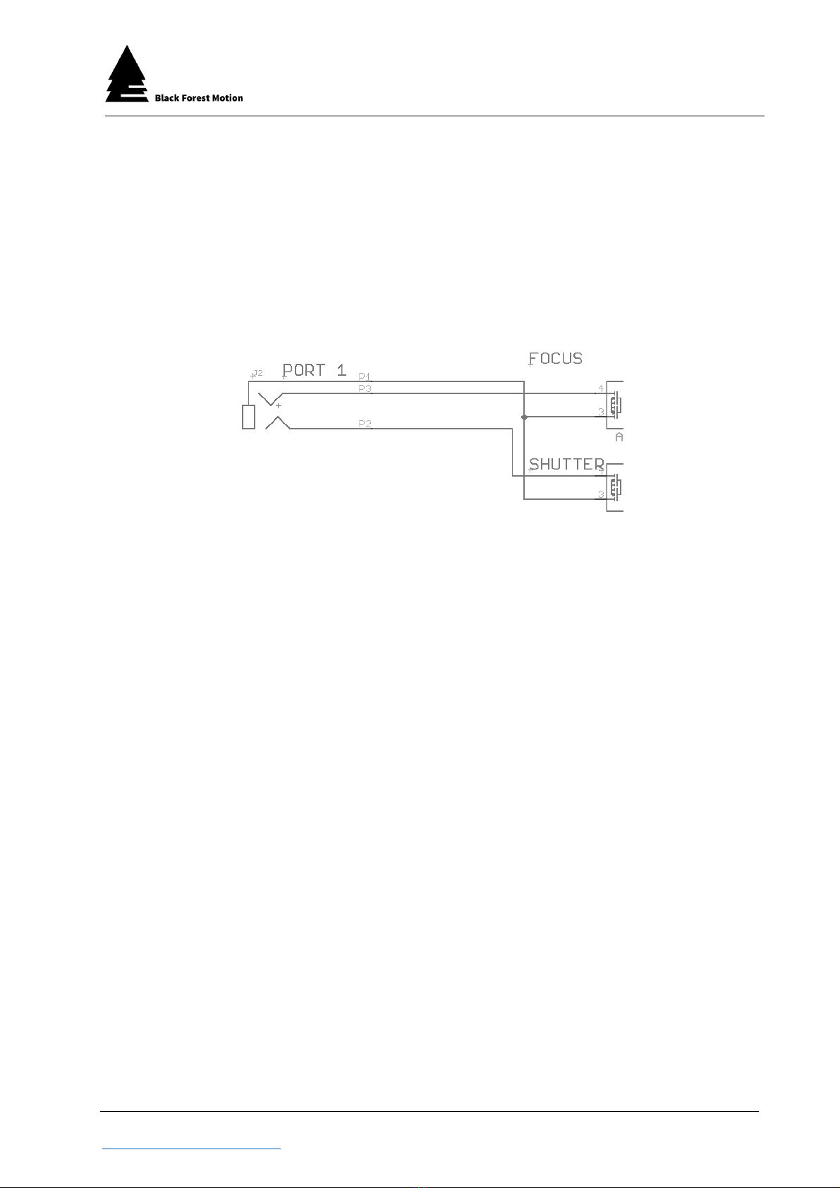
6.3.1. Technical Details of the Camera Ports
The PINE Controller has two potential-free, galvanically isolated open
collector/drain outputs (Solid State Relay) per camera socket. One output
controls the focus and the other the shutter release of the camera. Both
outputs are connected to the ground connector of the camera by the
PINE controller.
In the following, a symbolic representation of the internal wiring is shown:
6.4. AUX Input
In addition to the camera connections, the PINE Motion Controllers also have
a connection for an AUX input. This input can be used, for example, to control
a time-lapse motion with an external interval generator. The connector can
be connected to the flash sync connector of a camera or directly to the
corresponding interval generator.
A typical application is the use of the PINE motion controller with the stop trick
animation software Dragonframe.
The camera is controlled directly by Dragonframe via USB. The PINE can then
be operated in Slave Mode. For this purpose, the camera is connected to the
AUX port of the PINE controller via a special connection cable at the flash
synchronization connection.
In time-lapse mode, the interval setting must now be changed to SLAVE
MODE. With a corresponding delay time, the PINE moves the camera to the
next desired position after each image.
A similar application is the operation of the PINE Controller by an external
interval generator such as the VIEW by Timelapse+. This takes over the interval
and can then also carry out a so-called interval ramping.

Black Forest Motion GmbH
Waldstraße 2
78136 Schonach
Page 15 of 114
Black Forest Motion ▪PINE Controller User Manual
www.blackforestmotion.com ▪[email protected]
6.4.1. Technical Details of the AUX Input
The AUX input of the PINE Controller has two inputs which are internally
connected to 3.3V via pull-up resistors.
The following schematic shows the internal wiring of the AUX socket.
If the AUX input is used, the inputs must be connected to the ground
line via potential-free open collector/drain circuits.
So far, only the AUX_B input (front center pin of the TRS connector) is used.
The AUX_A input is reserved for later developments.
Do not connect any external voltages to the inputs of
the AUX socket! This can destroy the internal
components. Only use potential-free, open
collector/drain circuits (optocouplers or solid-state relay
outputs) to connect the input lines to the ground line.

Black Forest Motion GmbH
Waldstraße 2
78136 Schonach
Page 16 of 114
Black Forest Motion ▪PINE Controller User Manual
www.blackforestmotion.com ▪[email protected]
6.5. Power Supply of the Controller
Universal, rechargeable batteries and power supply units can be used for the
voltage supply. They should output a DC voltage in the range between 10
and 24V. We recommend a voltage of 12V.
Connected batteries and power supplies should be able to deliver at least
15W or 1.5A.
It is essential to use a suitable DC cable with a 2.1x5.5mm plug. The middle
"Center" connector must be positive.
Using other DC connectors (e.g. 2.5x5.5mm) can cause sudden restarts or
voltage losses. This might also result in connection problems with the App.
6.6. Mounting Options
To attach the PINE Controller to the Motion Control (Slider, Pan & Tilt, etc.)
different threads are attached to the bottom of the controller. The middle
thread is a ¼" UNC photo thread. This allows to attach the Controller to any
photo tripod or photo accessory. In addition, the PINE controller offers four
metric M4 threads that are specially arranged. Here, the mounting plate can
be mounted in two directions - horizontally and vertically. This plate can be
slid onto the Arca-Swiss profiles of the Nic-O-Tilt or slider and is held in place
by magnets.
¼“ UNC
M4
The PINE Controller can only be operated via the DC socket.
The USB socket is used for pure data transfer and firmware
updates and cannot be used for connecting power supplies
to the controller.

Black Forest Motion GmbH
Waldstraße 2
78136 Schonach
Page 17 of 114
Black Forest Motion ▪PINE Controller User Manual
www.blackforestmotion.com ▪[email protected]
7. Operation of the Controller
Please observe all above mentioned safety instructions before putting the PINE
Controller into operation! First connect all motors to the controller before
connecting the power supply. Make sure that all motors can move freely.
If you have connected the PINE controller to the motors, you can plug in the
power supply via the DC socket. The controller now starts its boot process.
Various tests of the internal components are carried out. All LEDs light up at
least once during the boot up process.
7.1. Boot-Up Process
After connecting the power supply, the boot process starts. The status LED
lights up red and flashes green at the same time. After a successful boot
process, the red status LED goes out and then remains flashing green. The
controller is then ready for operation and ready to establish a Bluetooth
connection with a smartphone.
If the status LED remains red even after several seconds, the boot process has
failed and the power supply must be disconnected and reconnected.
During the boot process, the blue Bluetooth connection LEDs also light up. In
these moments the wireless modules of the controller are checked and
initialized.
If the LEDs under the motor sockets light up red, the controller checks whether
motors are connected to the corresponding sockets. If a motor is connected,
it should make a short buzzing noise. If the motor has been successfully
detected, the motor LED changes to green. Otherwise, if no motor is detected,
the LED will turn off. If not all connected motors have been detected, check
the connectors and restart the controller.
If all LEDs of the controller flash red after connecting the
power supply, this indicates that the voltage is outside the
allowed specifications. Check that the voltage is between
10V and 24V.
Black Forest Motion GmbH
Waldstraße 2
78136 Schonach
Page 18 of 114
Black Forest Motion ▪PINE Controller User Manual
www.blackforestmotion.com ▪[email protected]
8. PINE Motion App
With the PINE Motion App, the PINE Controller can be controlled remotely. The
app is available for Android devices (version 4.3 or newer) and iOS devices
(iPhone 5 and newer / iOS 10.3 or newer). It can be downloaded from the
Google Play Store or App Store. More information can also be found on our
website.
Both versions of the app (Android and iOS) are almost identical. In some views,
however, the apps differ. In this chapter you will therefore find screenshot views
from both apps.
At the first start of the Apps, the permissions for different services have to be
granted. If the user does not grant them all, the app may not start. In this case,
uninstall the app and reinstall it. Enter all requested permissions.
8.1. Connection with a PINE Controller
After a successful boot process (status LED flashes green), the controller can
be connected to a smartphone and the PINE Motion App via Bluetooth.
First make sure that the PINE Motion App is installed on your smartphone.
Before starting the PINE Motion App, activate the Bluetooth function of your
smartphone. Some mobile phones also require an active GPS/location
function to establish a successful connection with the controller. The PINE
Motion app only uses GPS data to store your location in user-created XML files
in Giga-Pixel and 360-degree mode. Otherwise your GPS data will not be used
or stored.
Do not try to pair your smartphone with the PINE Controller
using the phone's Bluetooth settings. A Bluetooth
connection is handled exclusively via the PINE Motion App
and no Bluetooth settings need to be adjusted.

Black Forest Motion GmbH
Waldstraße 2
78136 Schonach
Page 19 of 114
Black Forest Motion ▪PINE Controller User Manual
www.blackforestmotion.com ▪[email protected]
After starting the PINE Motion App, it starts the Bluetooth scan process after
about 3 seconds and searches for a PINE Controller. If the "Auto-Connect”
option is activated, the app connects automatically as soon as a controller is
found. The controller indicates a successful and active Bluetooth connection
via a blue connection LED.
If the app does not find a controller after approx. 60 seconds, it stops the search
process to reduce the battery consumption. A new search process can be
started via the "Scan" or field.
If the "Auto-Connect" option is deactivated, you must tap on the "PINE" entry
as soon as the controller is within range and has been found. The "Auto
Connect" option can be activated and deactivated directly on the
connections screen in Android and can be changed under "Connections" in
iOS.
The demo mode of the app can be accessed via the "DEMO" field. Use this
mode to familiarize yourself with the app if you have not yet purchased a PINE
Controller.
Android iOS
It is recommended to close the app completely and start it
new with every new use. Do the same if you have problems
establishing a connection. In this case, restarting the
controller itself can also help.

Black Forest Motion GmbH
Waldstraße 2
78136 Schonach
Page 20 of 114
Black Forest Motion ▪PINE Controller User Manual
www.blackforestmotion.com ▪[email protected]
8.2. Motor Profiles / Motor Quick Setup
After successful Bluetooth connection, the Motor Quick Setup will appear (if
motors are connected). This selection can be used to set different motor
profiles for the motors. These motor profiles define settings such as motor gear
ratio and output current. For a correct function of the motors, all profiles
should be set correctly. Only in this case is it ensured that the motors move as
specified by the app. The appropriate profiles are already stored for the
motors, sliders and pan & tilt heads distributed via Black Forest Motion.
Android iOS
Take enough time to understand the need for motor
profiles. If the motors behave strangely, become very hot,
or make noises, there is a high probability that incorrect
profiles have been selected.
The "Default" profile within the app defines a motor
current of 0.4A. This is too low for many standard motors to
provide a proper function. Therefore, set the appropriate
profiles correctly.
This manual suits for next models
3
Table of contents


