Pan Bars Quick Start Guide
1
Pan Bars Quick Start GuidePan BarsQuick Start Guide
Chapter 1 Quick Start
Safety
•Do not use around flammable gas. All electrical equipment can
generate sparks that can ignite flammable gas.
•Keep the equipment dry. The system has not been made
weatherproof. Do not use with wet hands.
•Keep cables tidy. Use cable ties to keep them out of harm’s way. If
you have a head with slip rings then make use of them; avoid
running any cables between the base and the rotating head or
camera.
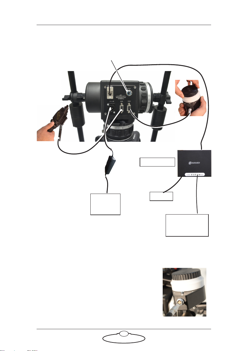
Overview
Thank you for using the Pan Bars from Mark Roberts Motion Control
(MRMC). Pan Bars is a Ethernet mimic controller for the MRMC camera
head. It gives you a smooth, precise and real-time control over your
choice of camera axes —pan and tilt, and camera control — zoom or
focus or both. Pan Bars are designed to work well with both Flair motion
control and MHC software systems by MRMC.
Pan Bars can have the following configuration:
Basic Pan and Tilt over Ethernet to either a FLAIR or MHC
computer with Zoom or Focus or both.
As a mimic encoder output to a Datalink system using a mimic
box (FLAIR): The Mimic Box is used to convert the raw
encoder data and provide Ethernet (redundant function as
already on basic Pan Bars) or Datalink which is needed for
legacy systems.
Pan Bars with Surface Pro (MHC): The Surface Pro is
networked to the Pan Bars via an Ethernet Hub and is just
mounted on the top of the Pan Bars for convenience of the
operator.
Pan Bars with an Ethernet or Datalink MSA joystick controller:
The Pan Bars provide mimic encoder inputs via Ethernet to the
MSA Joystick which then controls the Head via Ethernet or
Datalink.