Black Ice Audio F159 User manual

Owner's Manual
Black Ice Audio
Model F159
Phonograph Stage Tube Pre-Amplifier
With the Crosstalk Reduction Circuit
Black Ice Audio
21310 Ridgecroft Drive, Brookeville, MD 20833
Phone (301) 953-2014 Fax (301) 498-0554
Email: info@blackiceaudio.com Web: www.blackiceaudio.com
Dear Customer:

2
We at Black Ice Audio want to take this opportunity to thank you for purchasing the Black Ice F159 Phono Stage
Pre-amplifier. The author of the F159 is Jim Fosgate. Foz’s electronic design experience and excellence spans
decades and coupled with Black Ice Audio’s decades of manufacturing experience, results in a unit which can
provide our customers with a distinct improvement in turntable sound reproduction at an affordable price. In
addition your phono pre-amplifier has a Fosgate designed Crosstalk Reduction Circuit (XT-R) which represents
a distinctive electronic approach to solving crosstalk caused by a turntable’s cartridge and acoustic problems
due to axial tilt. We have placed the name F159 to honor the designer which we will detail in the backstory on
page 5.
Before using this unit, please take the time to carefully read and understand the safety instructions and operating
procedures before you install or attempt to operate your F159. Becoming familiar with important facts about your
F159 and its correct operation will help assure safe usage, maximum musical satisfaction, and reliable operation.
Take special care to follow the warnings indicated on the unit itself as well as the safety suggestions found in
the owner's manual. The effort you invest now will be well rewarded as time goes by.
Sincerely
Black Ice Audio
Table of Contents
Section Page No.
Safety Precautions 3, 4
Getting Started
Back Story 5
About Your F159 5
Construction and Testing 5
Handling Vacuum Tubes 5
Packaging 6
Accessories 6
Operating Procedures 6
Controls and Their Functions 6
Connections 7
F159 XT-R Circuit Calibration Instructions 8
Servicing 9
Warranty and Conditions 10
Technical Specifications 11
Important
Please Check your unit's bottom panel and record in the space below:
Model Number: F159
Serial Number:
Please fill out the warranty card enclosed with this package. If the warranty card is
not sent in, the warranty time will be reduced to one year. Keep your owner's manual
and receipt in a safe place for future reference.
3
SAFETY PRECAUTIONS
IMPORTANT SAFEGUARDS
PLEASE READ CAREFULLY ALL THE FOLLOWING IMPORTANT
SAFEGUARDS THAT ARE APPLICABLE TO YOUR EQUIPMENT.
_________________________________________________________________________
_________________________________________________________________________
_________________________________________________________________________
_________________________________________________________________________
SAFETY
1) Read the Safety Instructions in the Owner's
Manual - All the safety and operating instructions
should be read before the product is operated.
2) Retain the Owner's Manual - The safety and
operating instructions should be retained for future
reference.
3) Heed Warnings - All warnings on the product and
its operations should be adhered to.
4) Follow Instructions - All operating and use
instructions should be followed.
5) Power Sources - This product should be
operated using only the type of power source
indicated on the marking label. If you are not sure of
the type of power supply to your home, consult your
product dealer or local power company.
6) Grounding - This product is equipped with a
three-prong plug. Always use an electrical outlet that
is grounded. If you do not know whether the outlet
is grounded, consult your electrician or local power
company.
7) Power Cord Protection - Power supply cords
should be routed so that they are not likely to be
walked on or pinched by items placed upon or
against them, paying particular attention to cords at
plugs, convenience receptacles and where they exit
from the product.
8) Fuses - For continued protection against fire
hazard, replace fuses with the same type and rating
of the fuses specified. When changing fuses,
completely remove the AC cord from the wall outlet.
9) Tubes During Operation - While operating your
amplifier, do not touch the glowing tubes since this
may result in a severe burn.
10) Overloading - Do not overload wall outlets,
extension cords or integral convenience receptacles
to avoid the risk of a fire or an electric shock.
11) Lightning - For added protection for this
product during a lightning storm or when it is left
unattended and unused for long periods of time,
unplug it from the wall outlet.
CAUTION: TO REDUCE THE RISK OF ELECTRIC
SHOCK DO NOT REMOVE SCREWS.
NO USER-SERVICEABLE PARTS
INSIDE.
REFER SERVICING TO QUALIFIED
SERVICE PERSONNEL.
CAUTION
RISK OF ELECTRIC
SHOCK
DO NOT OPEN
The lightning flash with arrowhead symbol, within
an equilateral triangle, is intended to alert the user
to the presence of uninsulated “dangerous voltage”
within the product’s enclosure that may be of sufficient
magnitude to constitute a risk of electric shock
to persons.
The exclamation point within an equilateral triangle
is intended to alert the user to the presence of
important operating and maintenance (servicing)
instructions in the literature accompanying the
appliance.

4
SAFETY PRECAUTIONS CONTINUED
INSTALLATION
ENVIRONMENT
1) Water and Moisture - Do not use this product
near water - i.e., near a bathtub, wash bowl, kitchen
sink or laundry tub; in a wet basement; or near a
swimming pool or the like. Damp basements should
be avoided.
2) Heat - The product should be situated away from
heat sources such as radiators, heat registers,
stoves or other appliances that produce heat. Also
avoid putting the unit in the direct rays of the sun.
3. For indoor use only.
PLACEMENT
1) Ventilation - This product should not be placed in
a built-in installation or rack unless proper ventilation
is provided, or the manufacturer's instructions have
been followed. Never place anything on top your
amplifier that could obstructtheairflow andcausethe
electron tubes to overheat and damage the amplifier.
Do not place your amplifier in a closed bookcase;
overheating could result.
2) Foreign Material - Care should be taken to
prevent objects from falling into and liquids from
spilling into the unit. Do not subject this unit to
excessive smoke, dust, mechanical vibration, or
shock.
3) Surface - Place the unit on a flat level surface.
4) Accessories - Do not place this product on an
unstable cart, stand, tripod, bracket or table. The
product may fall causing serious injury to a child or
adult and serious damage to the product. Use only
with carts, stands, brackets or tables recommended
by the manufacturer or sold with the product. Any
mounting of the product should follow the
manufacturer's instructions and should use a
mounting accessory recommended by the
manufacturer.
5) Carts - A product and
cart combination should
be moved with care. Quick
stops, excessive force and
uneven surfaces may
cause the product and
the cart combination to
overturn.
6) Wall or Ceiling Mounting - The product should
be mounted to a wall or ceiling only as recommend
by the manufacturer.
MAINTENANCE
Cleaning - Unplug this product from the wall outlet
before cleaning. Do not use liquid cleaners or
aerosol cleaners. Use a damp cloth for cleaning. Do
not use any type of abrasive pad, scouring powder
or solvent such as alcohol or benzene.
SERVICE
1) Object and Liquid Entry - Never push anything
through the openings of this product which could
touch dangerous voltage or other hazards. Refer all
servicing to qualified service personnel.
2) Damage Requiring Service - Unplug this product
from the wall outlet and refer servicing to qualified
service personnel under the following conditions:
a) When the power-supply cord or plug is
damaged.
b) If liquid has been spilled or objects have
fallen in the product.
c) If the product has been exposed to rain or
water.
d) If the product does not operate normally
when following the operating instructions,
adjust only those controls that are covered
by these instructions. Improper adjustment
of other controls may result in damage that
will often require extensive work by a
qualified technician to restore the product to
its normal operation.
e) If the product has been dropped or
damaged in any way.
f) When the product exhibits a distinct
change in performance - this indicates the
need for servicing.
g) When the unit needs broken tubes to be
replaced.
3) Replacement Parts - When replacement parts
are required, be sure the service technician uses
replacement parts specified by the manufacturer or
parts with the same characteristics as the original
part. Unauthorized substitutions may result in fire,
electric shock or other hazards.
4)Tube Replacement - Should it become necessary
to replace your tube, carefully follow the instructions
in your Owner's Manual. When replacing your tubes,
remove the AC power plug from the wall and allow
thirty minutes for the high voltage capacitors to
discharge.

5
Getting Started
The Back Story:Suffice to say that Jim Fosgate (nicknamed “Foz”) is a World-Class Engineer and is the vision and
expertise behind the F159. His repertoire of achievement spans every category of audio electronic devices from two channel
audio, car audio, surround sound, headphone amplifiers to digital audio equipment. If one wants to experience a “live
experience of audio”, Foz’s sound room epitomizes the fusion of his designs in preamplifiers, amplifiers, source devices,
cables and speakers. His proficiency is not a matter of a blind squirrel finding an acorn. It is based on decades of document
research and experimentation of every possible major circuit approach, followed up by Foz building and auditioning the
circuits himself. Many people have asked us about the model number F159 which by most lights is rather like a fighter jet
designation. The F in the model number represents an abbreviation of Foz, and the 159 identifies the circuit as the one
hundred fifty-ninth iteration of the phono stage circuit that Foz has designed and built.
Another aspect of Foz’s expertise is manufacturing acumen. His designs reflect that somebody has to make the stuff and
complications are not the friend of manufacturers. Foz’s circuits are second to none in terms of sound reproduction, but
when the added dimension of creating a unit that uses parts off the shelf, ease of assembly and cost effectiveness, World-
Class Engineer is not a complement, it is an identification of fact.
About Your F159
Black Ice Audio’s F159 Phonograph Stage Tube Pre-Amplifier is an example of state-of-the-art vacuum-tube technology as
it exists today. This product was designed to provide: 1) a Phono Stage that would deliver musical accuracy 2) a significant
value based on a high performance to price ratio and 3) a vacuum tube unit that would exceed the reliability of solid-state
units. The F159 is housed in a Heli-arc welded chassis and uses 2 pieces of 6922/6DJ8 tubes. Parts quality is the best
currently available, and the overall circuit layout is maximized for sonic purity.
Another major feature of the phono stage is the inclusion of the XTR circuit or Cross Talk Reduction circuit. To obtain high
performance from a modern phonograph system, the tonearm and pickup cartridge must be properly adjusted to within a
few thousands of an inch to minimize the effect of axial tilt. Axial tilt is when the cartridge needle of the turntable is not
perpendicular to the record groove. In addition, a low dB channel separation of the cartridge can result in crosstalk.
Crosstalk is simply the stereo signal from the left side leaking into the right side, and the stereo signal from the right side
leaking into the left side. Jim Fosgate has designed an elegant electronic circuit to compensate for crosstalk and axial tilt.
The XT-R represents a breakthrough since axial tilt and crosstalk is not mitigated thru the traditional method of physical
adjustment, the compensation of the XT-R is electronic. The XT-R incorporates signal cancellation to reduce inter channel
crosstalk. This is the same technique that is used in high separation surround processors. The XT-R corrects for a
misaligned stylus or cantilever, misaligned generator, misaligned tone arm azimuth (axial tilt). It also reduces crosstalk
from cross coupling of the generator coils or tone arm wiring. This circuit works with moving magnet, moving iron, and
moving coil cartridges. The XT-R will compensate for up to 7 degrees of axial tilt and can improve channel separation to a
maximum of 48dB. The result will be an improvement in stereo imaging and clarity without any sacrifice in smoothness.
Construction and Testing
Like every Black Ice product, your F159 has been carefully hand-crafted, using precision mechanical parts. Electronic
components and assembly procedures are similar to those used in the manufacture of scientific equipment and musical
instruments. To assure consistent performance, each F159 is visually inspected at several assembly points, tested, and
electronically profiled prior to shipment.
This time-consuming perfectionist approach in the design and manufacture of audio equipment is intended to provide the
best in musical satisfaction with lasting value.
Handling Vacuum Tubes
Many may not have had experience handling vacuum tubes. However, most people have handled incandescent light
bulbs which is similar to dealing with vacuum tubes. As with light bulbs, you should not touch a vacuum tube when it is on
since you can burn yourself. Similarly, if a tube is dropped on a hard surface the tube will break. When you replace a
tube, you should make certain the unit is disconnected from the AC outlet and that the tube has cooled down. Never force
a tube into a socket. You should treat the tube gently when holding or replacing it. The precautions needed handling a
light bulb will give you a good guide on how to handle a vacuum tube.

6
Packaging
Save all the packaging in a dry place. Your Black Ice Audio phono pre-amplifier is a precision electronic instrument and
should be properly packaged any time shipment is made. It is highly probable that the unit will be damaged during shipment
if repackaged in a box and packing other than that designed for the unit.
You may have occasion to return the unit to the factory for service or shipment of the unit may be required for some other
situation. Should shipment prove necessary, the original packaging may save your investment from unnecessary damage,
delay and expense.
Accessories
1 AC Power Cord 1 pair of gloves
2 pieces of Chinese 772 factory 6DJ8 vacuum tubes 1 unit cover
2 pieces of Tung Sol 6922 vacuum tubes 1 microfiber cloth
Operating and Adjustment Procedure
1. Make sure you have read and complied with the CONTROL AND CONNECTION instructions prior to attempting to
operate your unit.
2. Make sure your F159 is properly connected to a high-current power receptacle via the attached power cord (see
Connections).
Controls and Their Functions: Front Panel
POWER switch:
Touch the logo to turn the power on or off. Source components of an audio system should be turned on first.
Otherwise, with some equipment, the amplifier will reproduce warm-up thumps.
dB Meter: Provides the readout as you adjust your turntable for axial tilt and crosstalk.
MeterAdjustmentScrew:For adjusting the readout of the dB meter. See “F159 XT-R Circuit Calibration Instructions”
on page 8, number 7 for instruction on resetting the reading on the dB meter.
Right and Left Adjustment Knobs, Activation and Calibration Switches: Please note that the procedure to
the XT-R circuit will be dealt with in the section “F159 XT-R Circuit Calibration Instructions”. The knobs and switches are
utilized in calibrating for crosstalk reduction and axial tilt compensation.
➎Viewing Port: Now tell that your unit is tube driven with a window exposing the 6299 vacuum tubes. Just so you know,
if you look closely into the window you can see Jim Fosgate’s signature on the circuit board.
7
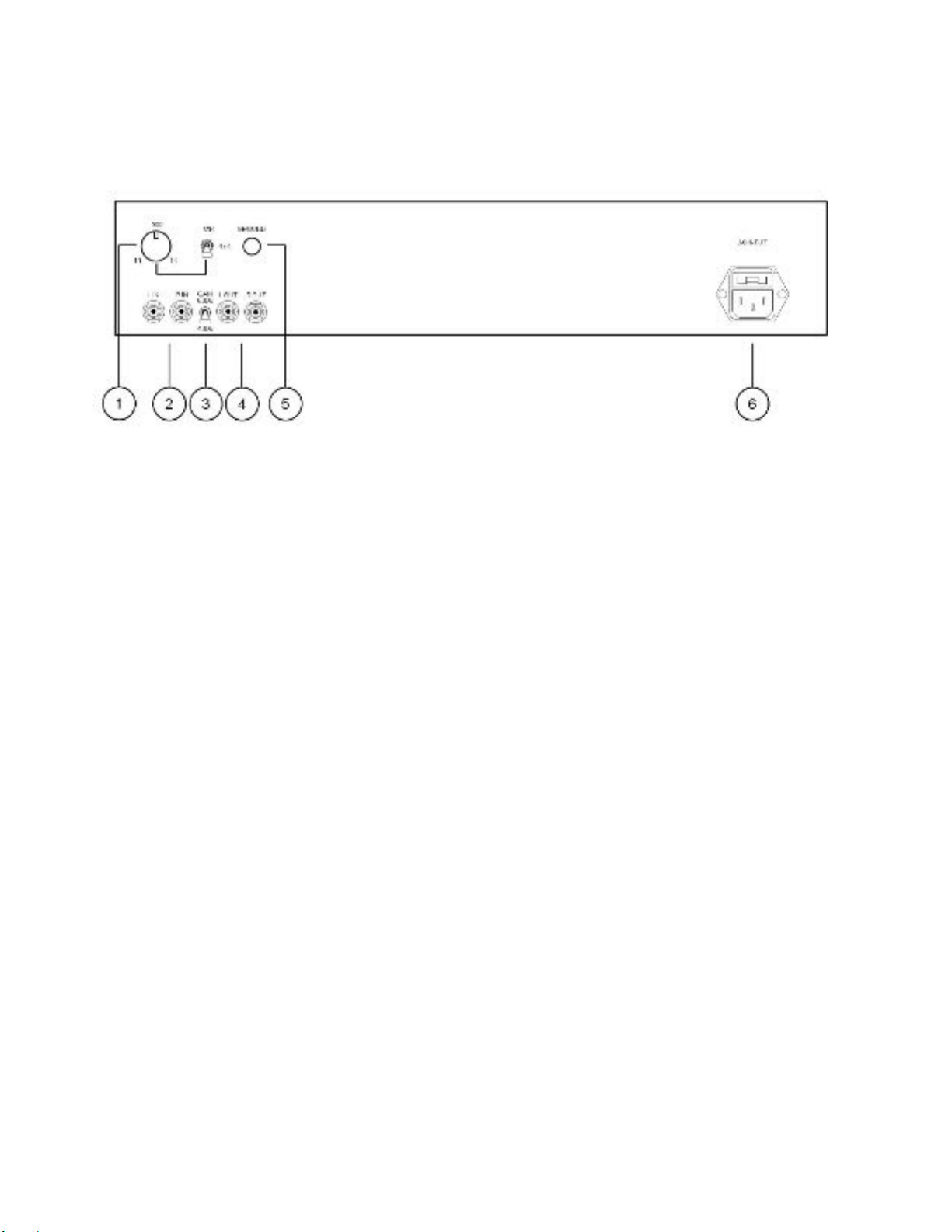
CONNECTIONS
Rear Panel
1. Loading: In phono preamplification, cartridge loading has a major influence on sound reproduction. If there is non-
optimal impedance matching between a cartridge and the input stage of the F159, optimal reproduction is reduced. A
loading resistance is required because electro-acoustic transducers (in your cartridge) must be damped to avoid ringing,
overshoot and other negative effects. The loading also influences the preamplifier's noise level, the frequency response,
etc. In essence, to reduce glare, midrange thinness and bloated bass, it is worthwhile to pay attention to adjusting your
loading properly.
Your loading is divided into two elements. A potentiometer/knob for variable loading adjustment, and a three-position
toggle switch. The first matter is to determine the impedance of your cartridge. Once that is determined you can now set
your loading. If your cartridge impedance is between 10 ohms and 1K ohms, you first position the three-way switch to the
lowest position. Then adjust the potentiometer to the approximate loading using the printed levels on the chassis as a
guideline. (counterclockwise to reduce, clockwise to increase) For example, if your cartridge is 750 ohms, you would set
the knob position halfway between the 500 ohms and 1K ohms setting. Please note that you can set the loading while you
are playing your turntable. With that, you can adjust the loading to your ear. What you are looking for is smooth extended
highs, tight bass and a rich midrange. If your cartridge is 47K ohms, you would position the three-way switch to the middle
setting. If your cartridge is 30K ohms, then you would position the three-way switch to the upper setting. Putting the switch
on the 47K/30K setting, turns off the variable setting. If you wish to experiment, you can adjust the loading to your ear
while you are playing a record.
2. Input Audio Signal Connection Jacks: Use these Left and Right RCA input jacks to attach the turntable outputs
to the phono preamplifier.
3. Gain Control: A two-way toggle switch: In the upper position the gain is 60dB and in the lower position the gain is
40dB.
4. Output Audio Signal Jacks: Use these left and right output jacks to attach the phono preamplifier to the inputs of
the preamplifier or integrated amplifier.
5. GROUND post: If needed, this post can be used to ground your turntable or other equipment in your system.
6. AC power connection: The F159 must be connected to a wall AC power receptacle, or a similar heavy-duty source.
Avoid the use of extension cords. If they must be used on a temporary basis, use 14-gauge or heavier cords. The power
cord on your F159 has a standard three-prong plug to provide maximum safety when it is connected to a wall receptacle. If
there is any question regarding the safety of grounding procedures, be certain to seek competent help with the installation.
For the built-in fuse, the value is 110/120 VAC 1 amp Fast Blow and for 220/240 VAC .50 amp Fast Blow. When replacing
the fuse, make sure that your F159 is unplugged from the wall. The fuse is located in the upper part of the IEC receptacle
in your preamplifier. Once you have removed the AC cord, you now have access to the fuse tray. If you run your finger
along the bottom of the fuse tray, there is a small notch. Using the notch remove the upper half of the receptacle by pulling
the cover out as if it were a tray. You may have to use a small flathead screwdriver to gently pry the tray out. Remove the
blown fuse and replace it with the spare. The spare can be found in the small rectangle box of the fuse holder.

8
F159 XT-R Circuit Calibration Instructions
Getting Ready:
In order to calibrate your Turntable, the F159 XT-R, it will require a Test LP. We use the Analogue Productions
Ultimate Analogue Test LP, but there are others that can be used if they have separate left and right channel
1KHz test tone signals.
Procedure for Crosstalk Correction:
1. Touch the logo to turn the power on.
2. Flip the toggle switch upward to the active position.
3. Flip the calibration switch to the left position. (Please note: When the switch is set in the middle, both right and left
channels are operating. When the switch is set to the left, only the left side signal is operating. When the switch is set to the
right, only the right-side signal is operating).
4. Play the azimuth adjustment track, left side, at a moderate volume. (The meter is now reading the right channel). Adjust
the left control knob for the lowest reading to the left which is called the signal “null point”. The exact meter reading is not
important, just set it to the null point. You may also notice that the right channel is quieter.
5. Flip the calibration switch to the right position.
6. Then play the azimuth adjustment track, right side at a moderate volume. (The meter is now reading the left channel)
Adjust the right control knob using the same procedure as with the left test tone to the signal null point. You may also
notice that the left channel is quieter.
7. Please Note: The meter reading will vary depending on the output level of the cartridge, channel separation of the
cartridge, and gain of the phono preamp. If the meter reads off scale to the right, check to be certain the channels are not
reversed. If the meter is still off scale to the right, then turn the meter adjustment screw clockwise. If the meter is off scale
towards the right, then turn the meter adjustment screw counterclockwise. The meter has a range of 30 DB and will not
usually need to be recalibrated.
8. Your correction process is completed. For the highest accuracy it is recommended you repeat the left and right
calibrations one more time
9. To play music return the calibrate switch to the center position and keep the active/off switch in the active position. You
can use this switch to hear the difference the crosstalk reduction has made. The most effective way to test the sound
difference is to play two minutes of a familiar record with the toggle switch in the off position. Then play the same section
of record in the active position.
10. Calibration will not change unless the cartridge alignment is changed, or a new cartridge is installed. Some cartridge
suspensions may change with age. We suggest that you perform a recalibration at six-month intervals.
Please Note: Phono Cartridge crosstalk has a great effect on sound stage depth and width, as well as the position of
sounds across the stage. When the crosstalk is “in phase” on both channels the stage width and depth will be reduced.
When the crosstalk is “out of phase” on both channels the stage will be wider and deeper. When azimuth is off the
crosstalk on one channel will be “in phase” and the other will be “out of phase”. This tilts the stage to one side or the other
and effects the positioning across the sound stage.
When the calibrate controls are turned clockwise towards the + side, the unit is correcting for “in phase” crosstalk. When
the control is adjusted counterclockwise to the –side the unit is correcting for “out of phase crosstalk”.
11. Have a FOZGOMETER, when calibrating your turntable, you can hook up your Fozgometer to the outputs of the F159
and use the meter instead of the meter on the front of your F159.

9
Replacing Your Tube
Included with your unit is a pair of Chinese 6DJ8s. We added these tubes to give you an option of tweaking your sound.
The Tung Sol 6922s that are installed in the unit shape a sound that is clear and transparent. The Chinese tubes will give
you a very smooth, lush and weighty sound but will be less clear than the Tung Sols. Have fun experimenting.
Should you replace your tubes make certain the preamplifier is unplugged from the wall AC receptacle and make certain
the unit has not been operating for at least thirty minutes. This allows the capacitors to discharge and the tubes to cool
down. Remove the cover. To remove the 6922 vacuum tube, use your thumb, index finger and middle finger to gently grasp
the vacuum tube on all sides. Hold the tube in the same manner as you would hold an incandescent light bulb. To remove
the tube from the socket, gently rock the tube from side to side while pulling up on it until the tube pins have been freed
from the socket. Never use excessive force.
Servicing
Because of its careful design and exacting standards of manufacture, your F159 should normally require only minimal
service to maintain its high level of performance.
CAUTION: The F159 contains sufficient levels of voltage and current to be lethal. Do not tamper with a component or part
inside the unit. Even with the power turned off, a charge remains in the energy storage capacitors for some time. Refer any
needed service to your authorized Black Ice dealer or other qualified technician.
The vacuum tubes inside the F159 are high-quality 6922/6DJ8 types. Reliable, low gas tubes - such as those available from
Black Ice - are strongly recommended for maximum performance and longevity.
Questions regarding your preamplifier may be referred to the Customer Service Department of Black Ice: (301) 953-2014.
We hope you enjoy your musical experience.

10
LIMITED WARRANTY
The Black Ice Audio F159 Stereo Tube Phono Preamplifier is warranted for the period
stated from the date of the original purchase.
1. Chassis and Transformers 2 years
2. Electron Tubes 1 year
WHO IS PROTECTED BY THIS WARRANTY
Your Black Ice warranty protects the original owner so long as the original bill of sale is presented when warranty service is required. In
addition, the warranty card included with your amplifier must be submitted within thirty days of purchase otherwise the warranty will be
good for only 1 year.
WHAT IS COVERED BY THE WARRANTY
Your Black Ice warranty covers all defects in material and workmanship with the following specified exceptions. These are: (1) Electron
tubes are warranted for 12 months (2) damage caused by accident, unreasonable use or neglect (including the lack of reasonable and
necessary maintenance); (3) modifications to the unit; (4) damage occurring during shipment (claims must be presented to the carrier);
(5) damage to or deterioration of any accessory or decorative wooden surface; (6) damage resulting from failure to follow instructions
contained in your owner's manual; (7) damage resulting from the performance of repairs by someone other than Black Ice or an
authorized Black Ice warranty station; (8) any Black Ice unit on which the serial number has been effaced, modified or removed; (9)
units used as demonstration or display models prior to purchase by the original consumer owner; (10) units used for the purpose other
than home use.
HOW TO OBTAIN WARRANTY PERFORMANCE
If your Black Ice unit ever needs service, write to us at Black Ice Inc., PO Box 218, Brookeville, MD 20833 (Att. Customer Relations
Department). We may direct you to an Authorized Black Ice Warranty Station or ask you to send your unit to the factory for repair in
which case we'll supply a Service Return Authorization and complete shipping instructions. Either way, you'll need to present the
original bill of sale to establish the date of purchase. Please do not ship your Black Ice unit to the Maryland address without our prior
communication.
If service under this warranty is not necessary, but you have questions regarding the installation or operation of your unit, please write
to our Customer Relations department at the address above.
WHO PAYS FOR WHAT
Black Ice will be happy to pay all labor and material expenses for all repairs covered by this warranty. If necessary, repairs are not
covered by this warranty, or if a unit is examined which is not in need of repair, you will be charged for the repairs or examination.
Although you must pay any shipping charges incurred in getting your unit to an authorized warranty station or to the factory, we will pay
return shipping charges if the repairs are covered by the warranty. Please be sure to save the original shipping cartons because a
nominal charge will be made for additional cartons.
LIMITATION ON IMPLIED WARRANTIES OF MERCHANTABILITY AND FITNESS FOR PARTICULAR PURPOSE ARE LIMITED
IN DURATION TO THE LENGTH OF THIS WARRANTY, UNLESS OTHERWISE PROVIDED BY STATE LAW.
EXCLUSION OF CERTAIN DAMAGES
BLACK ICE'S LIABILITY IS LIMITED TO THE REPAIR OR REPLACEMENT AT OUR OPTION, OF ANY DEFECTIVE PRODUCT AND
SHALL IN NO EVENT INCLUDE INCIDENTAL OR CONSEQUENTIAL COMMERCIAL DAMAGES OF ANY KIND.
SOME STATES DO NOT ALLOW LIMITATIONS ON HOW LONG AN IMPLIED WARRANTY LASTS AND/OR DO NOT ALLOW THE
EXCLUSION OF INCIDENTAL OR CONSEQUENTIAL DAMAGES, SO THE ABOVE LIMITATIONS AND EXCLUSIONS MAY NOT
APPLY TO YOU.
This warranty gives you specific legal rights and you may also have other rights which vary from state to state. We sincerely thank you
for your expression of confidence in Black Ice products. The amplifiers have been painstakingly assembled by highly trained crafts'
people. It should give you many years of musical enjoyment.

11
Fusion F159
Technical Specifications:
Basic Specifications:
1- Gain @ 1KHZ in low gain position 39DB with 47K input.
2- Gain @ 1KHZ in high gain position 59DB with 47K input.
3- Noise floor in high gain position approx -70 DB with input load set to 10 ohms, noise floor will be lower with gain
set in low position.
4- Frequency response with RIAA EQ is Plus/Minus 1/4 DB from 250 HZ to 20KHZ, + 3DB at 20 HZ (Bass Boost)
5- Distortion .05% @ 1 KHZ 1V RMS out.
6- Plate voltages APPROX 90V on input stage, 70V on second stage.
7- 2 pieces 6922/6DJ8 Vacuum tube complement
8- Fuse: 1 amp slo blow 5mm x 20 mm for 129 VAC and .50 amp for 220-240 VAC
9- Input Resistance: variable from 10 ohms to 1k ohms, 30K ohms, 47K ohms.
10. Weight: Unit: 18 pounds, Box and Unit: 22 pounds.
11. Unit Size: 17 inches wide, 12 inches deep, 3.5 inches high. Box Size: 22 inches wide, 18 inches deep, 10 inches
high.
12. Warranty: Two years parts and labor, one year on the tubes.

12
Black Ice Audio, Inc.
21310 Ridgecroft Road, Brookeville, MD 20833
Tel: (301) 953-2014 Fax: (301) 498-0554
Table of contents
Other Black Ice Audio Amplifier manuals

Black Ice Audio
Black Ice Audio Fusion F100 User manual

Black Ice Audio
Black Ice Audio Fusion 9 MK III User manual

Black Ice Audio
Black Ice Audio Fusion F35 User manual

Black Ice Audio
Black Ice Audio FUSION F360 User manual

Black Ice Audio
Black Ice Audio GLASS FX10 User manual

Black Ice Audio
Black Ice Audio FUSION F11 User manual
Popular Amplifier manuals by other brands

Krell Industries
Krell Industries Five-Channel Power Amplifier KAV-1500 Instructions for use

Lexicon
Lexicon LX-5 Specifications

Laney
Laney GS412IA operating instructions

ELECTROCOMPANIET
ELECTROCOMPANIET AW-250 owner's manual

Rockford Fosgate
Rockford Fosgate Mono Amplifiers Installation & operation manual

Kenwood
Kenwood KA-76 instruction manual


