manuals.online logo
Brands
  1. Home
  2. •
  3. Brands
  4. •
  5. Pioneer
  6. •
  7. Amplifier
  8. •
  9. Pioneer C-90S User manual

Pioneer C-90S User manual

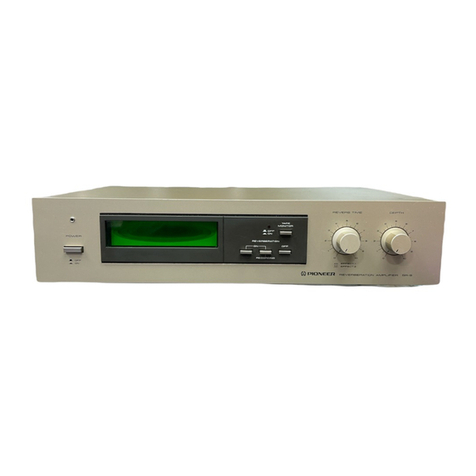
SPARE
PARTS
MASTER
STEREO
CONTROL
AMPLIFIER
C-90S
The
C-90S
is
equipped
with
the
audio/video
program-
mable
remote
contro!
unit.
The
“S"
at
the
end
of
the
model
number
indicates
that
a
programmabie
remote
con-
trol
unit
is
supplied.
The
panel
itself
says
C~90.
Operating
Instructions
Thank
you
for
buying
this
Pioneer
product.
Please
read
through
these
operating
instructions
so
you
will
know
how
to
operate
your
model
properly.
After
you
have
fi-
nished
reading
the
instructions,
put
them
away
in
a
safe
place
for
future
reference.
In
some
countries
or
regions,
the
shape
of
the
power
plug
and
power
outlet
may
sometimes
differ
from
that
shown
in
the
ex-
planatory
drawings.
However,
the
method
of
connecting
and
operating
the
unit
is
the
same.
WARNING:
to
prevent
FIRE
OR
SHOCK
HAZARD.
DO
NOT
EXPOSE
THIS
APPLIANCE
TO
RAIN
OR
MOISTURE.
IMPORTANT
NOTICE
[For
U.S.
and
Canadian
models]
The
serial
number
for
this
equipment
is
located
on
the
rear
panel.
Please
write
this
serial
number
on
your
enclosed
warranty
card
and
keep
it
in
a
secure
area.
This
is
for
your
security.
[For
Canadian
Model]
CAUTION:
ro
prevent
ELectric
sHOCK
DO
NOT
USE
THIS
(POLARIZED)
PLUG
WITH
AN
EXTENSION
CORD,
RECEPTACLE
OR
OTHER
OUTLET
UNLESS
THE
BLADES
CAN
BE
FULLY
INSERTED
TO
PREVENT
BLADE
EXPOSURE.
ATTENTION:
pour
prevenia
Les
cHocs
ELECTRI-
QUES
NE
PAS
UTILISER
CETTE
FICHE
POLARISEE
AVEC
UN
PROLONGATEUR
UNE
PRISE
DE
COURANT
OU
UNE
AUTRE
SOR-
TIE
DE
COURANT,
SAUF
SI
LES
LAMES
PEUVENT
ETRE
IN-
SEREES
A
FOND
SANS
EN
LAISSER
AUCUNE
PARTIE
A
DECOUVERT.
LINE
VOLTAGE
SELECTOR
SWITCH
Only
multi-voltage
models
are
provided
with
this
switch.
U.S.,
Canadian,
European,
U.K.,
and
Australian
models
are
not
provided
with
this
switch.
Mains
voltages
in
Saudi
Arabia
are
127V
and
220V
only.
Never
use
this
model
with
110V
setting
in
Saudi
Arabia.
The
line
voltage
selector
switch
is
on
the
rear
panel.
Before
your
model
is
shipped
from
the
factory,
this
switch
is
set
to
the
power
requirements
of
the
destination.
Check
that
it
is
set
properly
before
plugging
the
power
cord
into
the
AC
outlet.
If
the
voitage
is
not
properly
set
or
if
you
move
to
an
area
where
the
voltage
re-
quirements
differ,
adjust
the
selector
switch
as
follows.
1.
Use
a
medium-size
screwdirver.
2.
Insert
the
screwdriver
into
the
groove
on
the
voltage
selector,
and
adjust
so
that
the
tip
of
the
arrow
points
to
the
voltage
value
of
your
area.
—_
Medium-size
screwdriver
Sa
3.
Set
the
voltage
selector
switch
for
the
voltage
in
your
area.
110-120
vi
ee
v
e
®)
PIONEER’
The
future
of
sound
and
vision.
IMPORTANT
1
The
lightning
flash
with
arrowhead,
within
an
equi-
lateral
tiangie,
is
intended
to
alert
the
user
of
the
presence
of
uninsulated
“dangerous
voltage”
within
the
product's
enclosure
that
may
be
of
sufficient
magnitude
to
constitute
a
risk
of
electric
shock
to
persons
IMPORTANT
2
if
the
apparatus
is
fitted
with
AC
mains
power
out-
lei(e).
see
REAR
PANEL
FACILITIES
for
convenient
connection
of
additional
Hi-Fi
component(s).
Make
all
connections
to
the
AC
outlet(s)
and
the
signal
terminals
first,
Connect
the
plug
to
the
wall
socket
last,
make
sure
that
the
power
switch
is
off
CAUTION
RISK
OF
ELECTRIC
SHOCK.
DO
NOT
OPEN
CAUTION:
TO
PREVENT
THE
RISK
OF
ELECTRIC
SHOCK,
DO
NOT
REMOVE
COVER
(OR
BACK}.
NO
USER-SERVICEABLE
PARTS
INSIDE.
REFER
SERVICING
TO
QUALIFIED
SERVICE
PERSONNEL.
FOR
USE
IN
THE
UNITED
KINGDOM
The
wires
in
this
marns
lead
are
coloured
in
accor-
dance
with
the
following
code:
Blue
Neutral
Brown:
Live
READ
INSTRUCTIONS
—
Alt
the
safety
and
operating
instructions
should
be
read
before
the
appliance
is
operated
RETAIN
INSTRUCTIONS
-~
The
operating
instruc:
tions
should
be
retained
for
future
reference.
HEED
WARNING
~-
All
warnings
on
the
apphance
and
in
the
operating
instructions
should
be
adhered
to.
FOLLOW
INSTRUCTIONS
—
All
operating
and
use
instructions
should
be
followed.
WATER
AND
MOISTURE
—
The
appliance
should
not
be
used
near
water
—
for
example,
near
a
bathtub,
washbowt,
kitchen
sink.
laundry
tub,
in
wet
basement,
of
near
a
swimming
pool,
etc
LOCATION
-—
The
appliance
should
be
installed
in
a
stable
location
WALL
OR
CEILING
MOUNTING
—
The
appliance
should
mot
be
mounted
to
a
wall
or
ceiling
VENTILATION
--
The
appliance
should
be
situated
80
that
its
location
or
position
does
not
interfere
with
its
proper
ventilation.
For
example,
the ap-
pliance
shauid
not
be
situated
on
a
bed,
sofa,
rug,
or
similar
surface
that
may
block
the
ventilation
openings:
ar,
placed
in
a
built-in
installation,
such
as
3
bookcase
or
cabinet
that
may
impede
the
flow
of
air
through
the
ventilation
openings
HEAT
—
The
appliance
should
be
situated
away
from
heat
sources
such
as
radiators,
heat
registers,
stoves,
ot
other
appliances
(including
amplifiers)
that
produce
heat
POWER
SOURCES
—The
appliance
should
be
connected
to
a
power
supply
only
of
the
type
described
in
the
operating
instructions
of
as
marked
on
the
appliance.
POWER-CORD
PROTECTION
--
Power-supply
cords
should
be
routed
so
that
they
are
not
likely
to
be
walked
on
or
pinched
by
items
placed
upon
‘ot
against
them,
paying
particular
attention
to
cords
at
plugs,
convenience
receptacies.
and
the
point
where
they
exit
from
the
appliance
POLARIZATION
—
ff
your
purchased
product
is
provided
with
a
polarized
power
plug.
please
read
the
following
instructions.
This
product
is
equipped
with
a
polarized
alternating
current
line
plug
{a
plug
having
one
blade
wider
than
the
other).
This
plug
will
fit
unto
the
power
outlet
only
SAFETY
INSTRUCTIONS
POWER
LINES
—
An
outdoor
antenna
should
be
located
away
from
power
fines
NONUSE
PERIODS
—The
power
cord
of
the
appliance
should
be
unplugged
from
the
outlet
when
left
unused
for
a
long
period
of
time
OBJECT
AND
LIQUID
ENTRY
—
Care
should
be
taken
so
that
objects
do
not
fail
and
liquids
are
not
spilled
into
the
enclosure
through
openings.
DAMAGE
REQUIRING
SERVICE
—
The
anpliance
should
be
serviced
by
a
Pioneer
authorized
ser-
vice
center
or
qualified
service
personne!
when
©
The
power-supply
cord
or
the
plug
has
been
damaged:
or
©
Objects
have
fallen,
or
liquid
has
been
spilled
into
the
appliance;
or
®
The
apptiance
has
been
exposed
to
rain:
ot
©
The
apptiance
does
not
appear
to
operate
nor-
mally
or
exhibits
a
marked
change
in
perfor.
mance;
or
©
The
appliance
has
been
dropped:
or
the
enclosure
damaged
SERVICING
—The
user
should
not
attempt
to
service
the
appliance
beyond
that
described
in
the
operating
instructions.
For
alt
other
servicing,
contact
the
nearest
Pioneer
authorized
service
center.
POWER
LINES.
SERVICE
“
ENTRANCE
CONDUCTORS,
GROUND
WIRE
ab
The
exciamation
point
within
an
equilateral
triangle
is
intended
to
alert
the
user
of
the
presence
of
important
operating
and
maintenance
(servicing)
instructions
in
the
litereture
accompanying
the
appliance.
As
the
colours
of
the
wires
in
the
mains
lead
of
this
apparatus
may
not
correspond
with
the
coloured
marking
identifying
the
terminals
in
your
plug
proceed
as
follows:
The
wire
which
is
coloured
blue
must
be
connected
to
the
terminal
which
is
marked
with
the
letter
N
or
coloured
bleck
The
wire
which
is
coloured
brown
must
be
connected
to
the
terminal
which
is
marked
with
the
letter
&
or
coloured
red.
Equipment
sold
in
the
U.K.
is
not
supplied
with
2
power
piug
OUTDOOR
ANTENNA
GROUNDING
—
if
an
out~
side
antenna
is
connected
to
the
antenna
termi-
nat,
be
sure
the
antenna
system
is
grounded
so
as
10
provide
some
protection
against
voltage
surges.
and
built
up
static
charges.
in
the
U.S.A.
section
810
of
the
National
Elec-
trical
Code.
ANSI/NFPA
No.
70-1984,
provides
information
with
respect
to
proper
grounding
of
the
mast
and
supporting
structure,
grounding
of
the
lead-in
wire
to
an
antenna
discharge
unit,
size
of
grounding
conductors,
tocation
of
antenns-
discharge
unit,
connection
to
grounding
elec-
todes,
and
requirements
for
the
grounding
elec
trode.
See
Fig
A
a}
Use
No
10
AWG
(5.3
mm?)
cop-
per,
No
8
AWG
(8.4
mm*)
alu-
minum.
No.
17
AWG
(1.0
mm?)
copperciad
steel,
bronze
wire.
or
larget
as
ground
wire
6)
Secure
antenna
fead-in
and
ground
wires
to
house
with
stand-off
insulators
spaced
tram.
4
feet
(1.22
meters)
to
6
feet
(1.83
meters}
apart
c}
Mount
antenna
discharge
unit
as
closely
as
possible
to
where
lead-
wn
enters
house
STAND-OFE
d}
Use
jumper
wire
not
smatier
than
INSULATORS
Noe
AWG
(13.3
mm*)
copper,
or
the
equivalent,
when
a
sepa-
rate
antenna-grounding
electrode
is
used
See
NEC
Section
810-21
{j)
ANTENNA
LEAD
IN
WIRE
TO
EXTERNAL
ANTENNA
TERMINALS
OF
PRODUCT
ANTENNA
one
way.
This
is
a
safety
feature.
Hl
you
are
unable
ce
ewraance
gAouNe
OCRANGE
UNIT
¢
1o
insert
the
plug
fully
inte
the
outlet,
ty
reversing
Eguipaaent
eaOUNE.
the
plug.
Hf
the
plug
should
still
fait
10
fit,
contact
WIRE
a,b
your
electrician
to
teptace
your
obsolete
outtet
Do
not
defeat
the
safety
purpose
of
the
polarized
;
‘cRGUND
plug
POWER
SERVICE
CLEANING
—-
The
appliance
should
be
cleaned
only
GROUNDING
ELECTRODE
SYSTER
with
2
polishing
cloth
or
a
soft
dry
cloth.
Never
(©.9
terior
metal
water
pine}
clean
with
furniture
wax,
benzine,
ingecticides
or
ots
H
other
volatile
hquids
since
they
may
conede
the
it
amma
ey
cabinet
FIG.A
#8
LOCAL
CODES
SEE
‘BNET
SECTION
830.23
(1)
PS
CLAMPS
7
OPTIONAL
ANTENNA
GROUNDING
ELECTRODE
DRIVEN
&
FEET
(2.44
m)
2
<ARBI140>
CONTENTS
Before
Using
the
Unit
Features
Precautions
During
Use
Connections
-
Remote
Control
Operation:
Remote
Control
Unit
Use
of
Learning
Functions
-
Panei
Facilities
--
Operations
1
{Basic
Operations}
-
Operations
2
{Applications}
--
Troubleshooting:
Specifications
BEFORE
USING
THE
UNIT
Accessories
*
Remote
Control
Unit
---
Aa
*
“AAA”
size
{EC
LRO3
(AM-4)
alkaline
dry
cell
batteries:
*
Templates
added
«:----
©
Pin-Plug
cord:
This
equipment
generates
and
uses
radio
frequency
energy
and
if
not
installed
and
used
properly,
that
is,
in
strict
accordance
with
the
manufacturer's
instruc-
tions,
may
cause
interference
to
radio
and
television
reception.
It
has
been
type
tested
and
found
to
comp-
of
the
following
measures:
ly
;with
the
limits
for
a
Class
B
computing
device
in
:
accordance
with
the
specifications
in
Subpart
J
of
*
Par
16
of
FCC
Rules,
which
are
designed
to
provide
reasonable
protection
against
such
interterenbce
in
3
residential
instaitation.
However,
therre
is
no
guarantee
that
interference
will
not
occur
in
3
par-
ticular
installation,
receiver
cuits.
if
this
equipment
dees
cause
interference
to
radio
or
television
reception,
which
can
be
determined
by
tur-
ning
the
equipment
off
and
on,
the
user
is
encourag-
ed
to
try
to
correct
the
interference
by
one
or
more
reorient
the
receiving
antenna
relocate
this
equipment
with
respect
to
the
move
this
equipment
away
from
the
receiver
plug
this
equipment
into
a
different
outlet
so
that
equipment
and
receiver
are
on
different
branch
cir-
an
expaerienced
radio/television
technician
for
ad-
ditional
suggestions.
The
user
may
find
the
fallow-
ing
booklet
prepared
by
the
Federal
Communica-
tions
Commision
helpful:
“How
to
identify
and
REsolve.
Radio-TV
In-
terference
Problems”.
This
booklet
is
available
from
the
US
Government
Printing
Office,
Washington,
D.C.,
20402,
Stock
No.
004-000-00345-4,
The
above
instructions
apply
only
to
units
which
will
be
operated
in
the
United
States.
if
necessary,
the
user
should
consult
the
dealer
or
|
3
<ARB1I140>
FEATURES
MONO-CONSTRUCTION
Independent
power
transformers
are
provided
for
left
and
right
channels,
with
an
additional
transformer
for
control
and
display
functions.
This
three-transformer
design
prevents
deterioration
of
sound
due
to
interference
between
channels.
HYBRID
MC
TRANSFORMER
The
MC
transformer
winding
ratio
between
reduced
(1/2
of
previous
Pioneer
models},
thus
improving
low-frequency
and
high-frequency
MC
transformer
response.
VIBRATION-RESISTANS
DESIGN
In
order
to
eliminate
sound
deterioration
from
vibration,
the
amplifiers
supporting
legs
have
been
made
from
special
resin
material,
and
pure
aluminum
has
been used
for
the
volume
con-
trol
knob.
ELECTRONIC
CONTROL
Signal
switching
is
performed
by
relays
and
electronic
switches
in
order
to
shorten
the
signal
path,
thus
reducing
noise
and
im-
proving
separation
and
other
characteristics.
PRECAUTIONS
DURING
USE
HIGH-SOUND-QUALITY
MOTOR
DRIVE
VOLUME
CONTROL
Volume
control
is
performed
by
motor
drive,
thus
reducing
distor-
tion.
HIGH-FIDELITY
PARTS
All
parts,
from
circuit
boards
to
resistors,
capacitors,
semiconduc-
tors,
and
wiring,
have been
specially
developed
for
high-fidelity
audio
applications.
In
addition,
a
copper-plated
chassis
has
also
been
adopted
for
even
greater
sound
quality.
FULL
VIDEO
FUNCTIONS
In
addition
to
five
(plus
one
adapter)
audio
inputs,
five
(plus
one
adapter)
video
input
terminals
have
also
been
provided.
in
addi-
tion,
a
REC
selector
and
enhancer
function
have
also
been
built
in-
to
the
video
system.
AV
REMOTE
CONTROL
UNIT
WITH
LEARNING
FUNCTIONS
With
the
attached
remote
control
unit
you
can
operate
any
Pioneer
audio
or
video
component
bearing
the
mark.
And
with
additional
learning
functions
the
whole
AV
surround
system
including
TV
and
VCR
of
other
makers
can
be
controlled.
(Some
makers’
remote
control
systems,
however,
are
not
suitable
for
programming.)
ABOUT
INSTALLATION
Avoid
high
temperature
and
humidity,
and
allow
sufficient
ventila-
tion,
Excessive
heat
can
adversely
affect
internal
parts.
Avoid
foca-
tions
exposed
to
direct
sunlight
or
the
heat
from
a
space
heater
or
other
heating
appliance.
Also,
malfunctions
may
aresult
if
the
unit
is
installed
in
locations
with
high-humidity
or
high
concentra-
tions
of
dust.
{Also
avoid
kitchen
installations
or
other
locations
exposed
to
oily
smoke,
steam,
or
heat.)
4
<ARB1140>
PRECAUTIONS
FOR
INSTALLATION
To
ensure
optimum
sound
quality,
observe
the
following
precau-
tions:
*
This
unit
is
heavy.
Be
sure
to
install
it
on
a
firm
base
which
can
support
its
weight.
Also,
to
prevent
the
flow
of
cooling
air
from
being
blocked
off,
do
not
place
the
unit
on
soft
material
such
as
@
carpet
or
cushion,
or
install
it
in
a
confined
space.
When
in-
stalling
the
unit
in
a
rack,
provide
adequate
space
around
it
to
allow
heat
to
dissipate.
*
To
prevent
the
contro!
amplifier
from
picking
up
noise
due
to
leakage
flux
from
the
power
amplifier
when
the
control
amplifier
and
power
amplifier
are
installed
adjacent
to
each
other,
install
the
control
amplifier
on
the
right
of
the
power
amplifier.
Also,
if
you
install
the
control
amplifier
above
or
below
the
power
amplifier,
place
a
partition
between
them
to
separate
them
by
at
least
10
cm
from each
other.
install
the
unit
on
a
level
surface
so
that
the
feet
of
the
unit
are
ali
touching
the
installation
surface.
CONNECTIONS
AUDIO
COMPONENT
CONNECTIONS
Turntable
AM
antenna
FM
antenna
FM/AM
sterea
turner
Compact
disc
player
oe
When
used
with
Pioneer
power
amplifier
M-90,.
Sa
INPUT
—.
Rob
SV
®
©
et
@®
©
CO/LINE,
es
OUTPUT
Stereo
power
amplifier
Speaker
system
B
Speaker
system
A
tst
tape
deck
2nd
tape
deck
5
<ARB1140>
CONNECTIONS
*
Terminals
for
a
second
VCR
unit
are
located
inside
the
front
panel
door.
VIDEO
COMPONENT
CONNECTIONS
VHF
antenna
=
UHF
antenna
VHF
output
|
To
TV
Cone
output
[==
ae
ae
om
ws
VCR
[a
os
a
oo
VCR
Ist
VCR
Video
disc
player
Audio
Output
2/Right
—
/Lett
Not
necessary
when
RF
modulator
has
selector
switch.
VHF
IN
;
i
VHF
antenna
UHF
antenna
g
e
¢
Ea
er
/
7
\
VIDEO
IN
|
VIDEO
IN
TV
turner
with
video/audio
output
terminals
Normal
TV
set
Color
monitor
Color
monitor
{for
screen
monitor}
8
<ARB1140>
CONNECTIONS
W@
Connecting
Audio
Input/Output
Cords
(see
@
in
connection
diagrams)
*
Use
the
red/white
pin-plug
cords.
*
Connect
the
white
plug
to
the
Lileft)
channel!
and
the
red
plug
to
the
R{right)
channel.
Be
sure
to
insert
the
plugs
into
the
terminais
fully.
White
plug
L,
Red
plug
NOTES:
*
Short
pin
plugs
(I4
in
all)
are
fitted
to
each
of
the
AUDIO
IN
ter-
minals
for
PHOTO,
CD,
TUNER,
VDP,
VCR1,
VCR3,
and
TV
TUNER
to
improve
sound
quality.
Remove
these
when
making
connections.
¢
Keep
short
pin
plugs
in
a
safe
place.
Do
not
insert
in
the
REC,
AUDIO
OUT
or
VIDEO
IN,
OUT
terminais.
«
Replace
short
pin
plugs
in
the
terminals
from
which
have
they
were
removed
when
the
terminal
becomes
vacant.
Connecting
Video
Input/Output
Cords
(see
@)
in
the
connection
diagrams)
«
Use
pin-plug
cords.
*
Be
sure
to
insert
the
plugs
into
the
terminals
fully.
@.
CO
Pin-Plug
i
Connecting
an
RF
Modulator
(see
@)
in
the
con-
nection
diagrams}
*
Use
an
RF
modulator
designed
for
use
with
MSX
personal
computers.
«
Use
a
cord
with
5~pin
DIN
plug.
*
Align
the
depression
on
the
plug
with
the
guide
on
the
ter-
minal
and
insert
securely.
Depression
@
About
the
polarity
of
auxiliary
AC
power
outlets:
The
auxiliary
power
outlets
on
this
unit
have
marks
indicating
the
polarity
of
the
outlet.
When
connecting
other
stereo
com-
ponents,
if
those
components
have been
designed
with
specific
power
poiarity,
be
sure
to
connect
the
power
cords
in
accordance
with
the
manufacturer's
instructions
in
order
to
achieve
better
sound
quality.
The
negative
(ground)
side
of
the
rear
panel
outlets
are
indicated
by
a
dot
mark
{@).
7
<ARB1140>
REMOTE
CONTROL
OPERATION
LOADING
BATTERIES
1.
Open
the
battery
compartment
cover
on
the
rear
of
the
remote
control
unit.
The
cover
should
open
easily
if
you
slide
it
in
the
direction
of
the
arrow
while
pressing
on
it
with
your
thumb.
2.
Take
out
the
four
supplied
alkali
(LRO3/AM-4)}
batteries,
and
insert
them
into
the
battery
compartment
in
accordance
with
the
indications
in
the
compartment.
3.
Close
the
cover
of
the
battery
compartment.
Cover
¢
Reset
button
Incorrect
use
of
batteries
may
lead
to
leakage
or
rup-
ture.
Always
be
sure
to
follow
these
guidelines:
A.
Always
insert
batteries
into
the
battery
compartment
correctly
matching
the
positive
(+)
and
negative
(—)
polarities,
as
in-
dicated
inside
the
compartment.
B.
Never
mix
new
and
use
batteries.
Cc.
Batteries
of
the
same
size
may
have
different
voltages,
depen-
ding
on
their
type.
Do
not
mix
different
type
of
batteries.
D.
Both
rechargeable
and
non-rechargeable
batteries
are
available.
Be
sure
to
use
your
batteries
in
accordance
with
the
caution
labels
affixed
to
them.
8
<ARB1140>
RNAGE
OF
REMOTE
CONTROL
When
operating
the
remote
control
unit,
point
the
front
of
the
unit
at
the
front
pane!
of
this
unit.
The
remote
control
unit
may
be
used
within
a
range
of
about
7
meters
(23
feet)
from
the
remote
sensor,
within
angles
of
up
to
about
30
degrees.
These
figures
are
general
and
do
not
necessarily
apply
to
learned
commands.
reed
30°
S
7m
(23
feet)
Battery
Replacement
When
the
batteries
have
run
out,
the
transmit
indicator
will
not
il-
Juminate
even
when
a
key
is
pressed.
Be
sure
to
replace
the
bat-
teries
as
soon
as
possibie.
As
the
programmed
functions
will
be
retained
in
memory
only
as
long
as
batteries
are
insereted,
remove
the
old
batteries
only
if
they
can
be
replaced
by
new
ones
immediately.
Also,
be
sure
to
always
use
the
specified
dry
cell
batteries
(IEC
LRO3/AM-4
alkaline
batteries).
NOTE:
When
no
batteries
are
inserted,
the
programmed
memory
con-
tents
will
be
erased
after
30
to
60
minutes.
REMOTE
CONTROL
UNIT
FUNCTION
OF
THE
TRANSMIT
MODE
SELECTOR
SWITCH
AUDIO:
Select
this
position
for
remote
control
operation
of
audio
equip-
ment
such
as
CD
player,
tape
deck,
DAT
deck,
turntable
or
tuner.
VIDEO:
Select
this
position
for
remote
contro!
operation
of
video
equip-
ment
such.as
VDP,
VCR
or
TV.
AUX:
The
AUX
mode
is
provided
so
that
you
can
teach
the
remote
con-
trol
unit
extra
commands
in
case
you
have
filled
up
all
the
keys
in
the
VIDEO
and
AUDIO
modes.
If
you
do
not
programmed
into
any
new
commands,
then
only
the
amplifier
keys
will
operate
in
this
mode.
You
may
wish
to
use
this
mode
to
assign
commands
for
a
second
VCR,
tape
deck
etc.
_
¢
The
1-12
numerical
keys
are
used
for
DAT,
CD,
VDP,
TV
and
tuner
operation
in
both
the
AUDIO
and
VIDEO
modes.
/@
This
unit
function
keys
can
be
used
in
ail
three
modes.
*
Among
the
TV
function
keys
the
TV
POWER,
VCR/VDP/TV
in-
put
selector
and
volume
UP/DOWN
keys
are
operative
in
both
the
AUDIO
and
VIDEO
modes.
*
The
other
keys
may
be
assigned
commands
from
your
other
in-
frared
remote
control
units.
VIDEO
mode
VDP
function
keys
paws
eswer
Ske
Coayco
@
PIONEER
system,
fe
Cod]
CH
awmonoteg}
L
Com
teal
pean
VESLS
eno
Rewcre
GONTROR
Ue
<&
Set
the
TRANSMIT
mode
selector
switch
to
VIDEO,
VCR
function
keys
TY
function
keys
Turntable
function
keys
c-90
function
keys
{All
modes)
Set
the
TRANSMIT
mode
selector
AUDIO
mode
switch
to
AUDIO
DAT/TAPE
function
keys
DAT/TAPE
Selector
switch
CD
function
keys
Tuner
function
keys
TV
function
keys
(same
functions
in
both
the
AUDIO
and
VIDEO
modes)
oe
|
@Pioneen
AuOO
OED
PmcRamannaantn
Reker
Conn
_
STEN
EEYEE
Set
the
TRANSMIT
mode
selector
AUX
mode
switch
to
AUX,
—
0
©
transner
_
a
Ee
oe
|
Be
os
on
On
Oyo
aay
tame
i
on
CS
ee
ot
|
Gl
Go
Go
Ge;
“
|
<2)
=
a
OM
RET
ANT
aoe
epee
arta
ia
nes
eae
ee
cs
i
sa
ao
@
PIONEER
POGAARMA
ERE
BLOG
VED.
Femaore
Conran
cae
evsro
weet
teweo.
Hj
Ne
ec
Q
<ARB1140>
REMOTE
CONTROL
UNIT
Set
the
LEARN
selector
switch
to
USE
position.
TAPE
DECK
OPERATION
Set
the
TRANSMIT
mode
selector
switch
to
AUDIO.
MIDEO
AUDIO
«66
AUX
TAPE
function
keys
(operation
of
cassette
tape
deck
or
DAT)
DAT/TAPE
selector
switch:
Set
to
DAT
for
operation
of
the
DAT
(Digital
Audio
Tape)
deck,
and
TAPE
for
operation
of
the
cassette
tape
deck.
Explanations
in
square
brackets
[
J
are
for
the
DAT
deck
only.
©
(REC
MUTE)
key:
For
insertion
of
unrecorded
spaces
between
selections.
@
=
(REC)
key:
Selects
the
recording
mode.
If
(PAUSE)
key:
Temporarily
stops
the
tape
transport.
Press
again
to
resume
tape
transport.
I
(DECK
I)
key:
Switches
to
the
deck
I
functions
when
using
a
double
casette
tape
deck.
[DAT
PGM
key]:
Press
to
program
the
DAT
deck.
I
(DECK
II)
key:
Switches
to
the
deck
II
functions
when
using
a
double
cassette
tape
deck.
<q
(FF)
key:
Fast
forwards
the
tape
in
the
direction
of
the
arrow.
4
(PLAY)
key:
Selects
reverse
playback.
HM
(STOP)
key:
Stops
the
tape
transport.
&
(PLAY)
key:
Selects
forward
playback.
wb
(FF)
key:
Fast
forwards
the
tape
in
the
direction
of
the
arrow.
[1-0/10
(numeric)
keys]:
For
entering
desired
selections
into
the
memory.
[MEMORY
key]:
Stores
the
program
in
the
memory.
[CLEAR
key}:
Clears
the
program
stored
in
the
memory.
10
<ARB1140>
I
VCR
OPERATION
Set the
TRANSMIT
mode
selector
switch
to
VIDEO.
VIDEO
AUDIO
#¢46
AUX
VCR
function
keys
(operation
of
VCR)
©
VCR
POWER
key:
Switches
the
VCR
power
ON/OFF
@
=
(REC)
key:
Selects
the
recording
mode.
Il
(PAUSE/STILL)
key:
Sets
pause
and
still
picture.
I
VCR
CH
—
(DOWN)
key:
Shifts
channels
in
reverse
order.
IT
VCRCH
+
(UP)
key:
Shifts
channels
in
numerical
order.
<4<q
(REW)
key:
Rewinds
the
tape
and
allows
picture
search.
<4
ANT
key
*:
This
key
can
be
used
only
for
VCR
with
VCR/TV
selector.
Switches
the
antenna
output
VCR
to
TV.
@
(STOP)
key:
Stops
tape
transport.
B®
(PLAY)
key:
Selects
playback.
PP
(FF)
key:
Fast
forwards
the
tape
and
allows
picture
search.
REMOTE
CONTROL
UNIT
Note
on
DAT
operation
The
program
input
procedure
differs
slightly
from
that
of
the
remote
control
unit
supplied
with
Pioneer
DAT
decks.
Procedure
using
the
DAT
deck
ae
control
unit
1:
(I~)
key
>
2:
EY
key
+
3:
Repeat
steps
tT
and2>
4:
[BI
key
|
Procedure
using
the
programmable
remote
te
control
unit
i
(
Learn
O
Thanet
2)
ap
&
key
>
2:
G76)~
CSD
key
-
3:
vars
key
>
4:
Repeat
steps
2
and
USE,
LEARN
ate
Eatin
3-5,
[i
key
eB
fir
Direct
selection
with
the
remote
control
supplied
with
the
DAT
deck
|
(OMS)
key
>
2:
[E)
key
piece
selection
with
the
programmable
remote
control
Cea]
3]
1
key
>
2:
G
key
>
3:
)
key
:
oat
tarel
As
above,
#
DAT
function
key
must
be
pressed
before
entering
a
number.
fem
TAPE/VCR
Gat
Pam
Ce
1)
Ca)
Vee
SF
i)
*
For
switching
the
antenna
input
for
an
optional
VCR
(for
example
Pioneer
VH-900)
the
code
of
the
VCR
remote
contro!
must
be
memorized.
L
in
ee
Co)
comAT/VORP
:
wae
MEMORY
CLEARY
18/19-24"
FREGUENCY.
Es
Ba
CH
RETURN
CHANNEL
Are
os
eS
tye
rite
TM
BEARON
DUAL
Fest
Co
ca
‘oa
he
VOR:
H
aenai
C4
TAPE?
a)
el
ae
Be
‘VSB
NALSTINIG
Co
|
nian
Vette
[
es
es
ce
VOR
Aco
POWER
aaa
:
is:
@
pioneer
ALIDID
MIGEO:
PROGRAMMABLE
REMOTE
CONTROL
unit:
SYSTEM:
REMOTE:
CONTROL,
4
<ARB1140>
REMOTE
CONTROL
UNIT
Set the
LEARN
selector
switch
to
USE
position.
ME
CD
PLAYER
OPERATION
Set
the
TRANSMIT
mode
selector
switch
to
AUDIO.
MDEO
AUDIO
+66
4UXK
Om)
CD
Function
Keys
(Operation
of
CD
player}
KG<q
(TRACK
SEARCH)
key:
Returns
to
the
beginning
of
the
playing
track.
Pi
(TRACK
SEARCH)
key:
{Advances
to
the
next
track.)
DISC
SEL
key
Selects
the
DISC
No.
{1
to
6)
for
Multi-piay
CD
players.
PGM
key:
Press
to
program
the
CD
player.
<q
(MANUAL
SEARCH)
key:
Selects
fast
backward.
Hi
(PAUSE)
key:
Pauses
playback.
@
=
(STOP)
key:
Stops
playback.
>»
(PLAY)
key:
bP
(MANUAL
SEARCH)
key:
Selects
fast
forward.
1-0/10
(numeric)
keys:
For
direct
selection
of
a
track
or
programming
of
tracks.
MEMORY
key:
Memorizes
a
program.
CLEAR
key:
Erases
a
memorized
program.
©
tRansmir
a
[
LEARN
©.
USE,
LEARN
aun
Eun
TAPESVCR,
OAT
toon
FS
WOR
OM:
ANT.
(a)
[an
Ce) Gel
co/voP
OBC
SEL
RATTAN
a)
BER)
oGFCRY
Tae
es)
Oo
feat
Oo
&
<oe>
18
13
20
21
22
Ome
©
&
CD/DAT/VOrP
MEMGRY
CLEARAS12/71S-Ba:
PREGUENCY
12
23
24
CH-RETUAN
CHANNEL,
PHONG/YOR.
BA!
cane
eee
a}
fey
Cede
fOMP
FR:
TM
SEARCY
DUAL:
f3
ITV-POWER
VGH
MEW
TEM.
sau
VORA
VERE
VCRs
TWA
Voe
CoE
6
ES
FARES
TAPER
OD.
A
PON
fo
fo
fo
ea
ce
VSEC.
ee
EJ
bg
MUTING
.
Coy
Ce
}eeroncie}
MasTer|
fe
SLEEP
REAR:
EE
Wt
Lah"
ia
on
ES
AME
DELLA,
SUREDUNI
POWSR:
ct
MGOE
(2
PIONEER
AOI
VIDEO
PROGRAMMABLE
REMOTE
CONTROL
INET
4
SYSTEM
REMOTE
CONTROL.
EW
J
Note
on
CD
operation
The
program
input
and
direct
music
selection
procedures
differ
slightly
from
those
of
the
remote
control
unit
supplied
with
Pioneer
CD
players.
Programmed
playback
operation
using
the
CD
player
remote
control
unit
(1:
Disc
No.
(11~[6]
key)
+
2:
Track
No.
G)~[G
key
>
3:
TM"
key
~
4:
Repeat
steps
1
to
3
>
5:
key
Programmed
playback
operation
using
the
programmable
remote
control
unit
1:
(PEM)
key
-+
(2:
"=
key)
—
3:
‘MEMORY
qe
key
~
5:
Repeat
steps 2
t
Direct
music
selection
using
the
CD
player
remote
control
unit
(1:
Disc
No.
[)
3:
PS
key)
Direct
music
selection
using
the
programmable
remote
control
unit
(1:
BS
key)
>
2:
[PaM]
key
>
3:
G7D~CED
key
>
&
[=
key
As
above,
the
[P6M]
CD
operation
key
must
be
pressed
before
entering
a
number.
|
ae
~[6]
key)
>
2:
Track
No.
[~[G]
key
~
|
12
<ARB1140>
REMOTE
CONTROL
UNIT
Set
the
LEARN
selector
switch
to
USE
position.
W@
AMPLIFIER
OPERATION
AMPLIFIER
function
keys
(operation
of
this
unit)
INPUT
SELECTOR
keys:
Press
VCR1,
VCR2,
VCR3,
TV/AUX,
VDP,
CD,
TUNER
or
PHONO
to
switch
the
amplifier
input.
V.SEL
key:
After
pressing
the
V.SEL
key,
only
the
video
signal
can
be
changed.
The
selected
audio
signal
remains
as
set.
TAPE
MONITOR
keys:
Press
TAPE1,
TAPE2
to
switch
between
source
and
monitor,
MUTING
key:
Used
to
temporarily
mute
the
sound.
The
volume
is
restored
when
pressed
again.
AMP
POWER
key:
Switches
the
amplifier
power
ON/OFF.
MASTER
VOLUME
(+,—)
keys:
Adjusts
the
overall
(front
and
surround)
volume.
>
REAR
L,
R
volume
keys
%*
DELAY
TIME
key
+
SURROUND
keys
(
¢]4
)
%*
SURROUND
MODE
key
%*
DISPLAY
key:
*%*
SLEEP
timer
key
*
C-90
is
not
equipped
with
such
functions
as
REAR
L,
R
volume,
DELAY
TIME,
SURROUND,
SURROUND
MODE,
DISPLAY
and
SLEEP
timer,
Use
these
keys
for
learning.
Bs
C=)
MEMOS
CLEARY
1243-24)
FRERUENCY'
{BE
CH-RETURN
CHANNEL
Le
ES
efts
ThA
SEARCH
UAL:
7
Feeeren
vee:
TV
OMPLAY
vOR1
yoCRe
vCAS
Twaux
vOP.
TAPE:
CO
TUNER
PHONO
te
V.SEL
MUTING
(2)
surrouno
le}
MASTER
SLEEP
REAR
REAR
VOLUME
Ce
AMP
DELAY
SURROUND}
POWER
“TIME
MOGE
QO
PIONEER
ALIDIO.
VIDED
PROGRAMMABLE.
REMOTE
CONTROL:
Unit:
SYSTEM
REMOTE
i
Conte.
Al
43
<ARB1140>
REMOTE
CONTROL
UNIT
Set
the
LEARN
selector
switch
to
USE
position.
i
VDP
OPERATION
Set
the
TRANSMIT
mode
selector
switch
to
VIDEO.
VDP
function
keys
{operation
of
LD
player)
Kd<q
(CHAPTER
SKIP)
key:
Returns
the
beginning
of
the
present
chapter.
bbl
(CHAPTER
SKIP)
key:
Advances
to
the
next
chapter.
DISPLAY
call
key:
Clears
the
chapter
and
frame/time
displays
on
the
screen.
PGM
(PROGRAM)
key:
Allows
use
of
chapter
program
play,
frame
search
and
time
search.
4-4
(SCAN)
key:
Selects
fast
backward.
i
(PAUSE)
key:
Video
and
audio
are
stopped
and
playback
is
paused.
M@
=
(EJECT)
key:
Playback
is
stopped
when
pressed
once.
Pressing
again
causes
the
disc
tray
to
come
out
to
the
prescribed
loca-
tion.
®
(PLAY)
key:
Selects
playback.
>
(SCAN)
key:
Selects
fast
forward.
1
~
0/10
(NUMERIC)
keys:
Used
for
chapter
and
frame/time
number
search
and
for
chapter
program
play.
MEMORY
key:
Used
for
chapter
program
play.
CLEAR
key:
Used
for
releasing
repeat
playback,
number
correction
and
mode
release
during
search
operation,
and
for
releasing
chapter
program
play.
CHP/FR-TM
(CHAPTER/FRAME
-
TIME)
key:
Used
for
chapter
or
frame
{time}
search
operation.
SEARCH
key:
Used
for
the
search
operation
and
for
the
memory
repeat
operation.
414
<ARB1140>
teaesQ
QO
THaswrt
USE
LEARN
o
MIOEDL
TAPE/VOR
ae
2
tel
Ce
ANT
S
Cs
a)
Ee)
feo
co/vor
OSC
SEL
aa]
—]
[ese
a
re]
oa
Soar
Nee
MEMORY
CLEAR
a/isea
SREGLENCY
G2).
Cl)
CS)
Ce)
aS
Ba
CH-AETUAN,
CHANNEL
Pat
te)
ee)
fet
ed
ICHB7FR-
TM
SEARCH
DUAL
TV
BOWER
VER YOR
TO
OISRUAY}
it
Se
a
TY
VSEL
CH
MISTING
Co}
CS
lemoncis}
ioe
|
REAR.
:
a
ES
ae
AME
DELAY
2
euies
Poem
ov
Toe
2
QPIONGER
:
OED
VIDEO:
PROGRANIMABLE
REMOTE
CONTROL:
tunst,
SYSTEM
REMOTE
CONTROL
Set
the
LEARN
selector
switch
to
USE
position.
MB
TUNER
AND
TURNTABLE
OPERATION
Set
the
TRANSMIT
mode
selector
switch
to
AUDIO.
VIDEO
AUDIO
«ee
AUX
CUT
ceann
©
Rance
USE,
LEARN
aur
YEP
ax
TUNER
function
keys
(operation
of
FM/AM
Tuner}
TAPENCR
Oar.
1
to
12
(STATION
CALL)
keys:
|G)
oo
Go
OO
oe
For
recail
of
tuner
presets.
POWER
ant
‘
(a
C4)
Ce
2
Feo
i
1-12/13-24
(mode
selector)
key:
Landa
OAL
TARE
Switches
between
Mode
1
(1
to
12)
and
mode
2
(13
to
(oett
Eee
ea]
OF
24),
‘
)
Oe]
DO
oe
FREQUENCY
+
(UP):
ae
;
Shifts
the
frequency
up.:
CO)
@
ep)
’
FREQUENCY
—
(DOWN):
@
<n)
e
CO/DAT/VOr
Shifts
the
frequency
down.
MEMORY
CLEARI-12/13-24
FREGUENCY
.
23
24
ChH-RETURN
CHANNEL
BAND
key:
PRONOMOR
BAN
TW
Switches
the
FM
and
AM
(MW
and
LW)
bands
by
turns.
oe
ee)
Ee
ed
f
*
}
PHONO
function
keys
(operation
of
turntable)
»
(PLAY)
key:
peageny
faa
aw
al
i
pes
5
WERE
wa
hs
Ss
ee
Selects
play.
pa
eS
TAPES
CO
cae
t
M@
=
(STOP)
key:
cS
Stops
play.
MATING
Co
Celsronef
eS]
SLEEP
REAR.
pean
VOC
Co
9
[ao
Cad:
Power
ena”
Su
one
sme
Ss
Sa
Q
PIONEER
AUDI
VIDEO
PROGRAMMABLE
0!
REMOTE
CONTROL
SONIT
:
|
System
aemote
CONTROL
15
<ARB1140>
Set the
LEARN
selector
switch
to
USE
position.
MTV
OPERATION
Set
the
TRANSMIT
mode
selector
switch
to
VIDEO.
VIDEO
AUDIO
AUK
Cr)
TV
function
keys
(operation
of
component
display
or
projection
monitor
receiver)
1
to
12
(CHANNEL
CALL
DIGIT)
keys:
Used
to
call
up
channels.
CH-RETURN
key:
Returns
to
the
previously
received channel.
CHANNEL
+
(UP)
key:
Changes
the
channel
in
the
direction
of
larger
CHANNEL
CALL
DIGIT
numbers.
CHANNEL
—
(DOWN)
key:
Changes
the
channel
in
the
direction
of
smaller
CHANNEL
CALL
DIGIT
numbers,
DUAL
(MTS)
key:
Switches
between
MAIN,
SAP,
MAIN/SAP
and
(MONO).
See
the
TV
operating
instruction
for
details.
*
TV-VOL
+,
—
keys:
Raises
and
lowers
the
volume.
*
TV-POWER
key:
Switches
the
power
of
the
TV
ON/OFF.
*
VCR,
VDP,
TV
keys:
Switch
to
the
corresponding
input.
[Reference]
The keys
marked
with
“:k"
have
the
same
function
in
both
the
AUDIO
and
VIDEO
positions.
16
<ARB1140>
13
20,
et
Be
c
co/paT
VOR
MEMORY
CLEARY
12/13-2
FREGUENCY
12
CH)
+
24
CH-RETURN
CHANNEL
PHONG/VOR.
BANTD
Ty-VOt
=]
}
C
+]
OORT
WORST
YAUR
vor
ane
|
OBLAY.
‘POWER
TH
Ea
Ed
@
PIONEER
AUDIO
MIDRO
PROGRAMMABLE
REMOTE
CONTROL
LINst:
bs
SYSTEM
BeMOoTE
5
CONTROL
yor
Ty
GiSPLiay
ea
liens
|
USE
OF
LEARNING
FUNCTIONS
INTRODUCTION
This
system
remote
controller
may
“learn”
the
commands
of
other
remote
control
unit,
regardless
of
manufacturer,
as
long
as
the
other
unit
is
of
the
infrared
type.
in
some
cases
you
may
still
need
the
origina!
remote
control
unit
for
special
situations.
But
as
a
rule,
you
will
be
able
to
use
this
Pioneer
remote
for
most
system
control
needs,
including
video
as
well
as
audio
equipment.
NOTE:
When
using
the
“LEARN”
mode
it
is
a
good
idea
to
take
the
two
remote
control
lunit
to
another
room.
This
avoids
problems
such
as
sudden
high
volume
output
or
accidental
tape
erasure
that
may
occur
if
particular
infrared
command
signals
reach
your
com-
ponents.
Alternatively
you
may
wish
to
unplug
your
component
system.
Simply
turning
off
teh
power
may
not
be
sufficient
since
power
on/off
switching
may
also
be
remote
controllable.
WHICH
KEYS
CAN
BE
PROGRAMMED
WITH
NEW
COMMANDS?
There
are
two
mode
selector
switches
near
the
front
end
of
the
remote.
The
LEARN
mode
selector
lets
you
select
the
USE
or
LEARN
func-
‘tion.
The
LEARN
mode
allows
the
Pioneer
remote
to
“learn”
the
commands
of
other
remote
control
units.
The
USE
mode
allows
you
to
use
this
remote
control
unit
for
operation
of
your
system.
AUDIO
mode
iO
8
BB
£0
8
i
Io
q
ioe
OO
i
VIDEO
mode
The
keys
on
the
remote
control
unit
change
their
functions
accor-
ding
to
how
the
TRANSMIT
mode
selector
is
set.
You
can
switch
the
TRANSMIT
mode
between
AUDIO,
VIDEO,
and
AUX
modes.
However,
the
keys
in
the
SURROUND
AMPLIFIER
section
always
have
the
same
functions.
You
can
assign
new
commands
to
the
keys
in
each
of
the
modes.
In
the
AUX
mode,
all
keys
are
available
to
be
programmed
with
new
commands.
in
the
VIDEO
and
AUDIO
modes,
ail
keys
except
the
SURROUND
AMPLIFIER
keys
can
be
assigned
new
com-
mands.
When
you
first
start
using
the
remote
control
unit,
it
contains
in-
itial
commands
appropriate
for
Pioneer
equipment
(when
set
to
the
AUDIO
and
VIDEO
modes}.
If
your
audio
and
video
equipment
consists
of
Pioneer
components
exclusively
you
can
use
the
remote
control
unit
as
is.
It
is
also
possible
to
restore
the
original
Pioneer
commands
after
assigning
other
commands.
{Refer
to
“Returning
to
the
Initial
State”
for
this
procedure.}
*
in
each
mode
one
function
per
key
may
be
programmed,
for
a
total
of
up
to
154
functions.
*
When
a
presetting
keys,
make
sure
that
the
remote
control
units
of
both
this
and
theother
component
are
loaded
with
fresh
batteries.
*
For
some
special
types
of
infrared
remote
control
units
pro-
gramming
may
be
impossible.
AUX
mode
y
In
the
AUDIO
made
the
TAPE
func-
tion
keys
can
be
preset
with
new
functions
for
the
DAT
position
or
the
TAPE
position.
The
initial
i
settings
will
remain
in
the
other
position
(43
keys
can
be
programmed.).
28
IONE!
W200
VERQ
PROGR
ama
tLe
Bexaare
Sonn
Lae
{
Sree
ESYSTE
5
a
ee
I
|
’
In
the
VIDEO
mode
the
DAT/TAPE
1
switch
is
inoperative
{43
keys
can
be
programmed.}.
When
teaching
functions
whose
|
names
differ
from
those
of
the
|
keys,
write
in
the
names
or
codes
\of
the
functions
on
the
included
i
templates
and
place
on
the
panel.
i
All
buttons
can
be
preset
(68
keys
can
be
programmed.).
In
the
AUX
mode
the
DAT/TAPE
1
switch
is
inoperative.
47
<ARB1140>
USE
OF
LEARNING
FUNCTIONS
{Operation
Example]
Using
the
remote
control
unit
of
your
VCR
to
program
the
playback
command.
*
itis
recommended
that
the
name
of
the
key
and
its
function
cor-
respond.
This
is
convenient
when
operating
equipment.
2
Learn
@ @
TRANSMIT
USE,
LEARN
@--
el
TAPE/VCA
DAT.
o7]
e
Co
I
a)
VCR
=VCR
CH+
POWER
=
<3
a]
Ce
~~
v
AuDISY
eaux
(@
LEARN
indicator
This
indicator
shows
the
remote
control
unit
operating
condi-
tion.
tir:
Learning
is
possible.
OFF:
Regular
remote
contro!
functions
are
performed.
FLASHING:
Means
the
key
is
not
available
for
programming
a
new
com-
mand
in
the
current
mode.
@
TRANSMIT
indicator
This
indicator
flashes
when
remote
control
signals
are
sent.
@
LEARN
selector
switch
Set
as
follows:
LEARN:
This
position
is
used
for
storing
the
codes
of
your
remote
con-
tro}
unit.
USE:
Set
to
this
position
after
codes
have
been
stored
in
the
LEARN
position.
Set
to
this
position
for
normal
operation.
{Operation
example]
1.
Set
the
LEARN
selector
switch
of
the
programmable
remote
contro!
unit
to
the
LEARN
position
and
set
the
TRANSMIT
mode
selector
switch
to
the
VIDEO
position.
*
Programming
is
possible
with
the
TRANSMIT
mode
selector
switch
in
any
position,
but
VIDEO
is
used
as
an
example.
18
<ARB1140>
.
Place
the
transmission
sections
of
the
programmable
remote
contro!
unit
and
the
remote
contro!
of
the
VCR
facing
each
other.
1
to
2
inches
*
Place
the
two
units
on
a
table,
separated
by
2
to
5
cm
(1
to
2
inches).
Memorization
wili
not
be
possible
if
they
are
too
close.
.
Hold
down
the
VCR
PLAY
key
of
the
programmable
remote
control
unit
until
the
LEARN
indicator
fights
up,
then
release
the
key.
4.
Hold
down
the
PLAY
key
of
the
VCR
remote
control
unit.
.
Release
the
key
of
the
VCR
remote
control
unit
after
making
sure
that
the
LEARN
indicator
has
gone
out
on
the
Pioneer
remote
control
unit.
NOTE:
If
the
LEARN
indicator
flashes,
it
indicates
that
you
are
trying
to
preset
a
key
not
available
for
the
learning
function,
or
other-
wise
the
program
capacity
has
been
exceeded.
In
case
the
program
capacity
has
been
exceeded,
the
function
programm-
ed
last
will
not
be
memorized
correctly.
All
previously
pro-
grammed
functions,
however,
will
be
retained
in
memory
and
may
be
used
as
they
are
if
the
last
function
is
not
essentila.
For
re-programming
refer
to
page
19
“Returning
to
the
Initial
Settings”.
.
Set the
LEARN
selector
switch
of
the
programmable
remote
control
unit
to
the
USE
position.
*
The
previous
code
(Pioneer
uniform
remote
control
code
or
code
for
other
equipment)
is
erased
and
replaced
by
the
new
code.
.
Check
that
the
program
works.
*
Try
actual
operation
and
make
sure
the
unit
works
properly.
*
If
the
VCR
does
not
operate
when
pressing
the
key,
change
angle,
position
and
distance
between
both
remote
control
units
and
repeat
the
programming
procedure.
*
When
programming,
make
sure that
the
function
indica-
tions
(for
example,
D>,
DP,
HB)
on
the
other
remote
control
unit
and
the
programmable
remote
control
unit
are
the
same.
This
will
facilitate
operation.
USE
OF
LEARNING
FUNCTIONS
QUESTIONS
AND
ANSWERS
ABOUT
THE
LEARNING
FUNCTION
Q:
The
remote
control
unit
of
my
VCR
has
two
REC
(recording)
keys.
They
both
have
to
be
pressed
at
the
same
time
to
start
recording.
What
is
the
learning
procedure
in
this
case?
A:
Hold
one
of
the
keys
on
the
programmable
remote
con-
trol
unit
depressed
(for
example
the
VCR
@
key)
until
the
LEARN
indicator
lights
up,
and
then
press
the
two
keys
on
the
VCR
remote
contro!
simultaneously.
Q:
The
remote
control
unit
of
my
VCR
has
a
REC
(recor-
ding)
key
and
a
PLAY
(playback)
key
and
they
both
have
to
be
pressed
at
the
same
time
to
start
recording.
What
is
the
learning
procedure
in
this
case?
A:
Hold
one
of
the
keys
on
the
programmable
remote
con-
trol
unit
depressed
(for
example
the
VCR
@
key}
until
the
LEARN
indicator
lights
up,
and
then
press
the
REC
and
PLAY
keys
on
the
VCR
remote
contro!
unit
simultaneously.
*
As
described
above,
operations
which
require
two
keys
to
be
pressed
at
the
same
time
are
programmed
by
pressing
the
two
keys
simultaneously.
OPERATING
OTHER
EQUIPMENT
BY
THE
PRO-
GRAMMABLE
REMOTE
CONTROL
UNIT
1.
Set
the
LEARN
selector
switch
of
the
programmable
remote
control
unit
to
the
USE
position.
2,
Set
the
TRANSMIT
mode
selector
switch
to
the
desired
posi-
tion
(AUDIO/VIDEO/AUX).
*
Set
to
the
VIDEO
position
for
programming
as
described
in
the
exarnple.
3.
Press
the
key
of
the
desired
function.
*
The
TRANSMIT
indicator
fights
up
while
the
remote
control
unit
is
sending
codes.
NOTE:
*
When
operating
programmed
keys,
always
set
the
LEARN
switch
to
the
USE
position.
Operation
is
not
possible
in
the
LEARN
position.
*
For
functions
which
require
two
keys
to
be
pressed
at
the
same
time
(recording
etc.)
or
functions
for
which
several
codes
are
sent
simultaneously
(auto
functions,
timer
pro-
gramming,
etc.)
the
programming
procedure
is
different
and
improper
operation
may
occur.
RETURNING
TO
THE
INITIAL
SETTINGS
1.
Set
the
LEARN
selector
switch
to
the
LEARN
position.
2.
Remove
the
battery
cover.
Cover
3.
Press
any
of
the
keys
available
for
programming.
The
LEARN
indicator
will
illuminate.
4.
Use
a
ball-point
pen
or
simitar
object
to
press
the
RESET
key
while
the
LEARN
indicator
is
flashing.
Reset
button
*
The
programmed
functions
for
the
AUDIO,
VIDEO
and
AUX
positions
are
cleared,
and
theremote
control
unit
is
reset
to
the
Pioneer
uniform
remote
contro!
codes.
*
Press
the
button
gently;
do
not
use
excessive
force.
19
<ARB1140>
PANEL
FACILITIES
FRONT
PANEL
@
MAIN
POWER
switch
STANDBY
switch/indicator
«
When
the
power
switch
is
in
the
ON
position,
power
can
be
turned
ON/OFF
to
the
amplifier
and
to
the
rear
panel
REMOTE
CONTROL
power
outlets.
Power
is
turned
ON/OFF
alternately
with
each
press
of
the
switch;
when
in
the
OFF
(stand-by)
position,
the
indicator
will
light
(when
in
the
ON
position,
the
indicator
will
flash,
then
go
out).
The
accessory
remote
control
unit
can
be
used
to
turn
this
switch
ON/OFF,
with
the
result
that
the
remote
control
unit
can
be
used from
the
listening
position
to
control
power
not
only
to
the
amplifier,
but
also
to
those
components
con-
nected
to
the
rear
pane!
REMOTE
CONTROL
power
outlets.
*
When
not
using
the
amplifier
for
an
extended
period
of
time,
be
sure
to
set
the
main
power
switch
to
the
OFF
posi-
tion.
@
VIDEO
SIGNAL
SELECTOR
switch
Use
to
switch
the
video
component’s
video
signal
regardless
of
the
position
of
the
input
selector
switch.
The
video
in-
dicators
(green)
above
the
input
selector
switch
will
light
in
order.
Even
when
listening
to
an
audio
component
(record
player,
tuner,
etc.},
this
switch
can
be
used
to
perform
video
recor-
ding
and
playback
while
continuing
to
listen
to
the
audio
com-
ponent
playback.
@
VIDEO
INPUT
selector
switches/indicators
Use
to
select
the
video
component
for
playback.
{vDP]—————_
To
play
back
the
video
disc
player
connected
to
the
rear
panel
VDP
terminals.
{VCR}
To
play
back
the
VCR
connected
to
the
rear
panel
VCR1
terminals.
IVCR2]
-
To
play
back
the
VCR
connected
to
the
front
panel
VCR2
terminals.
20
<ARB1140>
Front
panel
door
Press
lower
side
SS
{VCR3)
—~
To
play
back
the
VCR
connected
to
the
rear
panel
VCR3
terminais.
{TV
tuner]
——
To
use
the
TV
tuner
connected
to
the
rear
panel
TV
TUNER
terminais.
The
red
indication
light
during
audio
playback,
while
the
green
in-
dicators
light
during
video
playback.
This
switch
is
interlocked
with
the
AUDIO
INPUT
selector.
@®
AUDIO
INPUT
selector
switches/indicators
Use
to
select
the
audio
component
for
playback
(the
indicator
will
light).
{CD}:
For
compact
disc
player.
{Phono}:
For
turntable.
{Tuner}:
For
listening
to
FM/AM
broadcasts
with
a
tuner.
{Tape
1]:
To
use
the
tape
deck
connected
to
the
rear
panel
Tape
1
terminals.
{Tape
2]:
To
use
the
tape
deck
connected
to
the
rear
panel
Tape
2
terminals.
The
Tape
1
and
2
switches
go
ON
or
OFF
alternately
each
time
they
are
pressed,
independently
of
the
other
switches.
@)
VOLUME
control
Use
to
adjust
the
sound
volume.
At
the
[o>]
position,
sound
will
not
be
heard,
while
at
the
[0]
position,
sound
volume
will
be
at
its
maximum.
@®
REMOTE
SENSOR/indicators
@
VIDEO
ADAPTOR
switch/indicator
Set
to
the
ON
position
when
using
the
component
connected
to
the
rear
panel
ADAPTOR
terminais
VIDEO
IN
and
OUT.

Other Pioneer Amplifier manuals

Pioneer GM-A6604 User manual

Pioneer

Pioneer GM-A6604 User manual

Pioneer VSA-E08 User manual

Pioneer

Pioneer VSA-E08 User manual
Pioneer BP-320 User manual

Pioneer

Pioneer BP-320 User manual

Pioneer GM-X822 X1R/UC User manual

Pioneer

Pioneer GM-X822 X1R/UC User manual

Pioneer A-207 MLXJ User manual

Pioneer

Pioneer A-207 MLXJ User manual

Pioneer PRS-D200 User manual

Pioneer

Pioneer PRS-D200 User manual

Pioneer PRS-D4100F/XU/UC User manual

Pioneer

Pioneer PRS-D4100F/XU/UC User manual

Pioneer M-EV51 User manual

Pioneer

Pioneer M-EV51 User manual

Pioneer KEH-P7200RDS User manual

Pioneer

Pioneer KEH-P7200RDS User manual

Pioneer KEH-M7300 User manual

Pioneer

Pioneer KEH-M7300 User manual

Pioneer A-229 User manual

Pioneer

Pioneer A-229 User manual

Pioneer C-AX10 User manual

Pioneer

Pioneer C-AX10 User manual

Pioneer SA-5500II User manual

Pioneer

Pioneer SA-5500II User manual

Pioneer SPEC-1 User manual

Pioneer

Pioneer SPEC-1 User manual

Pioneer GM-X962 User manual

Pioneer

Pioneer GM-X962 User manual

Pioneer PRS-D4200F - Premier Amplifier User manual
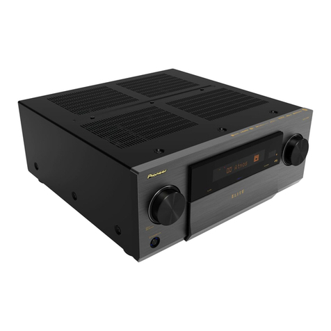
Pioneer

Pioneer PRS-D4200F - Premier Amplifier User manual

Pioneer AVM-P7000R User manual

Pioneer

Pioneer AVM-P7000R User manual

Pioneer GM-D8604 User manual

Pioneer

Pioneer GM-D8604 User manual

Pioneer GM-6000F User manual

Pioneer

Pioneer GM-6000F User manual

Pioneer GM-D8400M - Amplifier User manual

Pioneer

Pioneer GM-D8400M - Amplifier User manual

Pioneer PRS-X340 User manual

Pioneer

Pioneer PRS-X340 User manual

Pioneer GM-D8601 User manual

Pioneer

Pioneer GM-D8601 User manual

Pioneer A-702R User manual

Pioneer

Pioneer A-702R User manual

Pioneer A-A6MK2-K User manual

Pioneer

Pioneer A-A6MK2-K User manual

Popular Amplifier manuals by other brands

Kenwood KAC-6405 instruction manual

Kenwood

Kenwood KAC-6405 instruction manual

Rockford Fosgate Punch X150.1 Installation & operation

Rockford Fosgate

Rockford Fosgate Punch X150.1 Installation & operation

Etnyre SAM Black-Topper Manual supplement

Etnyre

Etnyre SAM Black-Topper Manual supplement

Mechanics & Electronics ME3000-V quick start guide

Mechanics & Electronics

Mechanics & Electronics ME3000-V quick start guide

technetix AIMA3000.EDFA Product user manual

technetix

technetix AIMA3000.EDFA Product user manual

Bose FreeSpace IZA 2120-LZ Installation and operating guide

Bose

Bose FreeSpace IZA 2120-LZ Installation and operating guide

Harman Kardon CITATION 16 brochure

Harman Kardon

Harman Kardon CITATION 16 brochure

Audio Note ONGAKU Kensei Owner's Information

Audio Note

Audio Note ONGAKU Kensei Owner's Information

Bogen BPA-60 Installation & use manual

Bogen

Bogen BPA-60 Installation & use manual

Bakoon SATRI AMP-51R owner's manual

Bakoon

Bakoon SATRI AMP-51R owner's manual

Rolls VP29 owner's manual

Rolls

Rolls VP29 owner's manual

Denon AVP-A1HD Product review

Denon

Denon AVP-A1HD Product review

Key Digital Phantom KD-HDDA1X2 operating instructions

Key Digital

Key Digital Phantom KD-HDDA1X2 operating instructions

Audio General PA2X20 user manual

Audio General

Audio General PA2X20 user manual

Ekinex EK-50Q-AU user manual

Ekinex

Ekinex EK-50Q-AU user manual

Dynacord L1300FD-AU installation manual

Dynacord

Dynacord L1300FD-AU installation manual

AudioSource AMP800VS owner's manual

AudioSource

AudioSource AMP800VS owner's manual

Optimus MA-30M Installation and operating instructions

Optimus

Optimus MA-30M Installation and operating instructions

manuals.online logo
manuals.online logoBrands
  • About & Mission
  • Contact us
  • Privacy Policy
  • Terms and Conditions

Copyright 2025 Manuals.Online. All Rights Reserved.