Black Ice Audio GLASS FX10 User manual

Owner's Manual
BLACK ICE AUDIO
GLASS FX10
Integrated Stereo Tube Amplifier
Black Ice Audio
21310 Ridgecroft Drive, Brookeville, MD 20833
Phone (301) 953-2014 Fax (301) 498-0554

2
Dear Customer:
We at Black Ice Audio want to take this opportunity to thank you for purchasing the FX 10 Integrated
Stereo Tube Amplifier. The company that stands behind your amplifier draws on a decade of tube
design and manufacturing experience. Backed by a wealth of engineering knowledge, we are
committed to providing our customers with the highest level of quality sound at an affordable price.
This commitment has resulted in audio amplifiers that have the sonic characteristics of stereo tube
amplifiers costing two to three times as much. Black Ice Audio has achieved this goal through
modern design principles, quality parts, craftsmanship and strict attention to efficient purchasing and
production. We are confident that your amplifier will provide you with years of listening pleasure.
Before using this unit, please take the time to carefully read and familiarize yourself with the safety
and operating instructions before you install or attempt to operate your FX 10 integrated amplifier.
Knowing important facts about your amplifier and its correct operating procedures will help assure
safe usage, maximum musical satisfaction, and reliable operation. Take special care to heed the
warning signs on the unit itself as well as following the safety suggestions found in the owner's
manual. Please read the section on tube layout which will give you information on tube replacement.
The effort you invest now will be well rewarded as time goes by.
Sincerely
Black Ice Audio
Table of Contents
Section Page No.
Safety Precautions 3, 4
Getting Started
About Your Amplifier 5
Construction and Testing 5
Packaging/Unpacking 5, 6
Accessories 6
Preparation for Use 6
Operating Procedures 6
Controls and Their Functions 7
Connections 8
Vacuum Tube Layout: 9,10
Tube Replacement 10
Biasing 10, 11, 12, 13
Servicing 13
Warranty and Conditions 14
Technical Specifications 15
Important
Please Check your unit's bottom panel and record in the space below:
Model Number: FX10
Serial Number:
Please fill out and return the warranty card enclosed. If the warranty card is
not sent to us, the warranty time will be reduced to six months. Keep your owner's
manual and receipt in a safe place for future reference.

3
SAFETY PRECAUTIONS
IMPORTANT SAFEGUARDS
PLEASE CAREFULLY READ ALL THE FOLLOWING
SAFEGUARDS THAT APPLY TO YOUR EQUIPMENT.
_____________________________________________________________________
_____________________________________________________________________
______________________________________________________________________
______________________________________________________________________
SAFETY
1) Read the Safety Instructions in the Owner's
Manual. These instructions should be read
before the product is operated.
2) Retain the Owner's Manual - The manual is
important for future reference on safety and
operational matters.
3) Heed Warnings - All warnings on the product
and in the operating instructions should be adhered
to.
4) Follow Instructions - All operating instructions
should be followed.
5) Power Sources - This unit should be operated
only by using the type of power source indicated on
the marking label. If you are not sure of the type of
power supply to your home, consult your product
dealer or local power company.
6) Grounding - This unit is equipped with a three-
prong plug. Only use an electrical outlet that is
grounded. If you do not know whether the outlet is
grounded, consult your electrician or local power
company.
7) Power Cord Protection - Power supply cords
should be routed to avoid being walked on or
pinched by items placed upon or against them. Pay
particular attention to cords at plugs, convenience
receptacles and where they exit from the product.
8) Fuses - For protection against fire, replace fuses
with one of the same type and rating. When
changing fuses, unplug the AC cord from the wall
outlet.
9) Tubes During Operation - To prevent burns, do
not touch the glowing tubes while operating your
amplifier.
10) Overloading - Do not overload wall outlets,
extension cords or integral convenience receptacles
to avoid the risk of a fire or an electric shock.
11) Lightning - During a lightning storm or when
your unit is left unattended and unused for long
periods of time, unplug it from the wall outlet.
12) Glass Cover –Do not strike the glass cover
with any hard object, otherwise the glass may be
broken.
CAUTION: TO REDUCE THE RISK OF ELECTRIC
SHOCK DO NOT REMOVE SCREWS.
NO USER-SERVICEABLE PARTS
INSIDE.
REFER SERVICING TO QUALIFIED
SERVICE PERSONNEL.
CAUTION
RISK OF ELECTRIC
SHOCK
DO NOT OPEN
The lightning flash with arrowhead symbol, within
an equilateral triangle, is intended to alert the user
to the presence of uninsulated “dangerous voltage”
within the product’s enclosure that may be of sufficient
magnitude to constitute a risk of electric shock
to persons.
The exclamation point within an equilateral triangle
is intended to alert the user to the presence of
important operating and maintenance (servicing)
instructions in the literature accompanying the
appliance.

4
SAFETY PRECAUTIONS CONTINUED
INSTALLATION
ENVIRONMENT
1) Water and Moisture - Do not use this unit near
water - i.e., near a bathtub, wash bowl, kitchen sink
or laundry tub; in a wet basement; or near a
swimming or wading pool. Damp basements should
be avoided.
2) Heat - Keep the unit away from heat sources
such as radiators, heat registers, stoves or
appliances that produce heat. Also avoid putting
the unit in the direct rays of the sun.
3. For indoor use only.
PLACEMENT
1) Ventilation - Ensure that proper ventilation is
provided and that the manufacturer's instructions
have been adhered to if the unit is placed in an
enclosed cabinet or rack. Never obstruct the top
portion of your amplifier with objects that prevent
proper ventilation. Overheating could damage the
amplifier. Do not place your amplifier in a closed
bookcase, overheating could result.
2) Foreign Material - Ensure that small object
and/or liquids do not fall into the unit. Prevent
exposure to excessive smoke, dust, mechanical
vibration, or shock.
3) Surface - Place the unit on a flat level surface.
4) Accessories - Do not use carts, stands, brackets
or tables that are unstable. Use accessories
recommended by the manufacturer or sold with the
product. Any mounting for this unit should follow
the manufacturer's instructions and should be one
recommended by the manufacturer.
5) Carts - A unit with a cart
combination should be
moved with care. Quick
stops, excessive force and
uneven surfaces may
cause the product and
the cart combination to
overturn.
6) Wall or Ceiling Mounting - The product should
be mounted to a wall or ceiling only as
recommended by the manufacturer.
MAINTENANCE
Cleaning - Unplug this unit from the wall outlet
before cleaning. Do not use liquid or aerosol
cleaners. Use a damp cloth for cleaning. Do not
use any type of abrasive pads, scouring powders
or solvents such as alcohol or benzene.
SERVICE
1) Object and Liquid Entry - Never push any
objects through the unit’s openings. They may
touch dangerous high voltage wires or other
hazardous objects. Refer all servicing to qualified
service personnel.
2) Damage Requiring Service - Unplug the unit
from the wall outlet and refer servicing to qualified
service personnel when:
a) The power-supply cord or plug is
damaged.
b) Liquid has been spilled or objects have
fallen into the unit.
c) The unit has been exposed to rain or
water.
d) The product does not operate normally
when following the operating instructions.
Adjust only those controls that are covered
by the operating instructions as improper
adjustment of other controls may damage
the unit and require extensive repair by a
qualified technician to restore it to normal
operations.
e) The unit has been dropped or damaged
in any way.
f) The unit exhibits a distinct change in
performance - this indicates the need for
service.
g) Broken tubes need to be replaced.
3) Replacement Parts - When replacement parts
are required, be sure replacement parts specified
by the manufacturer or parts with the same
characteristics as the original parts are used.
Unauthorized substitutes could cause fire, electric
shock or other hazards.
4) Tube Replacement - When replacing tubes,
carefully follow the instructions in your Owner's
Manual. Be sure to unplug the AC power cord
and allow at least thirty minutes for the high voltage
capacitors to discharge their voltage.

5
Getting Started
About Your Amplifier: FX 10
Black Ice Audio's FX 10 integrated vacuum-tube stereo amplifier provides state-of-the-art technology in vacuum-
tube amplifiers. The design objectives for this unit were three-fold: 1) to provide an amplifier that would improve
musical accuracy to the fullest for such products, 2) to provide the consumer with a quality amplifier at a price
far below other tube amplifiers, and 3) to provide an all-vacuum tube amplifier that would approach the reliability
of good solid-state amplifiers.
The FX 10 is housed in a Heli-arc welded chassis and the cover utilizes heat resistant safety glass. The unit
uses two matched pairs (4 pieces) of EL38/6BQ5 power output tubes, two 12AX7 for the pre-amplifier. The FX
10 is rated at 10 watts per channel RMS. The quality of its parts is the best currently available, while the overall
circuit layout maximizes sonic purity. Since the FX 10 already has a built-in pre-amplifier, all that is required for
a sound system is two speakers of 4 or 8 ohms and a CD player.
Construction and Testing
Like every Black Ice Audio product, your FX 10 amplifier has been designed and carefully hand-crafted, using
precision mechanical parts. Electronic components and assembly procedures used in its manufacture are
similar to those used in the manufacture of scientific equipment and musical instruments. To assure consistent
performance, each FX 10 is visually inspected at several assembly points, test run, electronically tested and
sonically evaluated prior to shipment.
This time-consuming, perfectionist approach to the design and manufacture of audio equipment is intended to
provide you with the best and lasting musical satisfaction.
Handling Vacuum Tubes
Vacuum tubes should be handled the way incandescent light bulbs are handled. As with light bulbs, you should
not touch a vacuum tube when it is operating. The tubes are as fragile as light bulbs and can shatter when
dropped on hard surfaces. When replacing a tube, make certain the tube is disconnected from the AC outlet
and that the tube has cooled down. Never force a tube into a socket. Treat the tube with care when holding or
replacing them. Remember, take the same precautions when handling tubes as when handling light bulbs.
Packaging
Save all the packaging in a dry place. Your Black Ice Audio amplifier is a precision electronic instrument and
should be properly packaged any time shipment is made. Because of its weight (12 pounds), it is highly
probable that the unit will be damaged during shipment if repackaged in a box or container other than that
designed for the unit.
You may have occasion to return the unit to the factory for service or some other situation that requires the
shipment of your unit. Should it prove necessary to ship it, the original packaging may save your investment
from unnecessary damage, delay and expense.
Unpacking
The FX 10 is packed within a custom-made impact absorbing foam wrap that holds the amplifier in the carton.
Because of the unit weight and because it is a precision electronic instrument, it is necessary to take reasonable
care in its unpacking and preparation for use.

6
Unpacking Con't
When unpacking it is best to have a open work. Set the carton upright in the center of the work area and, with a
small knife, carefully slit the tape. Open the top of the box and lift the inner foam wrap housing the amplifier out
of the box and place it on a flat surface. Very carefully, remove the amplifier from the bottom foam. Carefully
remove the plastic wrap. Reassemble the carton system immediately and save for future use.
Accessories: 1 AC Power Cord, MP3 cable, remote control
Preparation for Use
1. Place your amplifier on a flat surface.
2. Your amplifier is shipped with the tubes in the sockets covered with foam. Before operating the amplifier, the
top and the foam around the speakers need to be removed. First, place the amplifier either on right or left side.
Unscrew the four feet. This will detach the glass top. Turn the unit upright holding the glass top to the amplifier
chassis. Remove the glass top, remove the foam, make sure the tubes are in straight and firmly in place. Place
the glass top back on and use the feet to screw the top back to the chassis.
Note: Contact Enhancers are not recommended for use on vacuum tube contact pins. With continual exposure
to heat and air, these substances can form gummy, dust-collecting residues which actually reduce contact and
degrade sonic performance. Proper external use of this preparation - on interconnect plugs, speaker
connections, etc. - is left to the discretion of the owner.
Operating and Adjustment Procedure
1. Make sure you have read and complied with the CONTROL AND CONNECTION instructions prior to
attempting to operate your unit.
2. Make sure your FX 10 is properly connected to a high-current power receptacle via the attached power
cord (see Connections).
3. Attach the audio sources and speakers to the FX 10.
4. Before you turn on the amplifier, make sure the speaker connections are properly hooked up. Never run
the amplifier without speakers hooked up since it may damage the transformers.
5. Your FX 10 will now operate satisfactorily. However, a full stabilization or warm-up period of at least 5
minutes is recommended for best sonic performance.
The amplifier should always be turned on and off via its own power on-off switch. Further, other discrete
components of an audio system should be turned on first. Otherwise, with some equipment, the amplifier will
reproduce warm-up thumps, etc., some of which could be harmful to your speaker system.
7
Controls and Their Functions
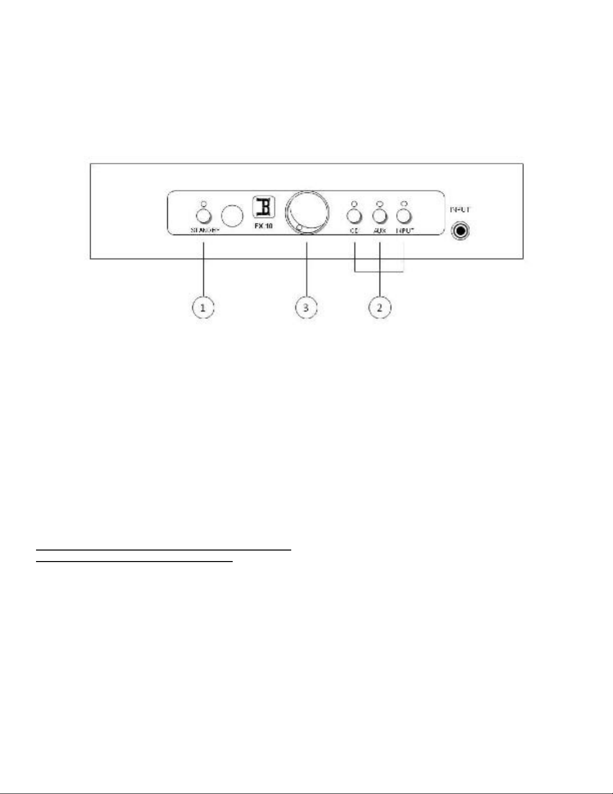
Front Panel
1. POWER switch:
On the back of the amplifier, is a rocker panel switch that needs to be turned on. Once the rocker panel switch is on, the
on/off indicator on the front will be red. Then press the on/off switch on the front of the amplifier to turn the power on. The
indicator should be will blink and after 15 seconds will be lit blue. After a few seconds, the tubes on the top panel will
begin to glow a soft blue and orange color. Press the switch to turn the unit off, the indicator light should turn red to
indicate the unit is in standby. Do not turn your unit on without the speakers being hooked up.
It is normal for a vacuum tube power amplifier to run quite "warm", and if used for prolonged periods, "hot" to the touch.
All components operate at safe, conservative levels and will not be damaged. Do not touch the tubes during operation or
for ten minutes after the unit is turned off, otherwise touching may result in a burn.
Further, other discrete components of an audio system should be turned on first. Otherwise, with some equipment, the
amplifier will reproduce warm-up thumps, etc., some of which could be harmful to your speaker system.
Note: Black Ice Audio does not recommend leaving your
FX 10 "on" 24 hours a day 7 days a week as is the custom of some audiophiles to achieve maximum sonic performance
on demand. While this is often recommended for solid-state equipment, Black Ice Audio does not recommend this
procedure for vacuum tube amplifiers.
Since the tubes in your amplifier are rated for a minimum of 3,000, you may have to replace the tubes every four months.
2. SELECTOR switch:
Used to select the audio source to be heard. There are three selection positions that can be chosen by pressing the
buttons or using the remote. The front input is an 1/8-inch connector used for iPod or MP3 players.
3. Volume control:
This control adjusts the output volume level. Turning the control knob clockwise increases the sound level and turning it
counterclockwise decreases the sound level.
8
CD AUX
8ohm 4ohm 0
OUTPUT
AC INPUT
ON
OFF
L
R
1
2
3
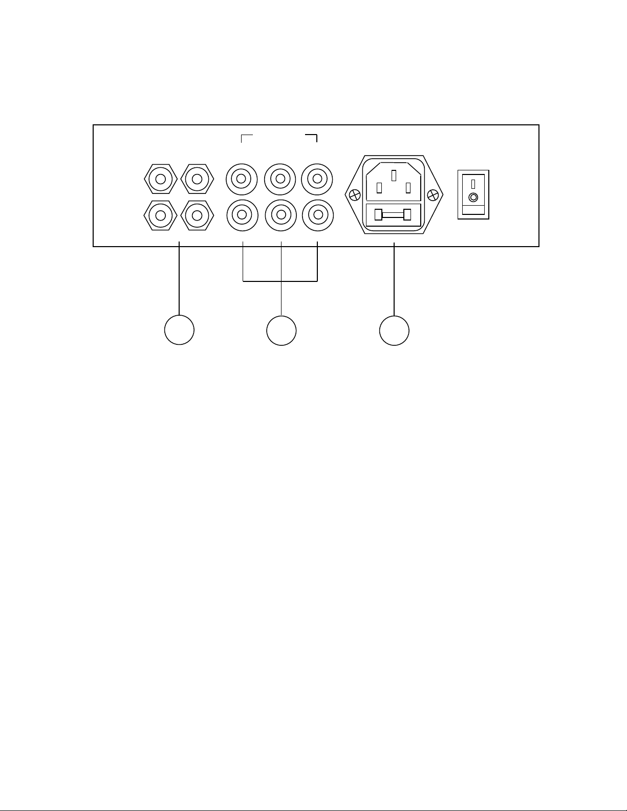
CONNECTIONS
Rear Panel
1. AUDIO signal connection jacks
Use these jacks to connect the audio signal cords
from your components to the amplifier. The audio
signal cords should be connected to the proper input
output jacks for each unit. Note, one can hook the
tuner into the tape or the CD into the Auxiliary,
however, this will defeat the purpose of the selector
switch. Be sure to observe the proper polarity. That
is, connect the right channels of the amplifier to the
corresponding right channels of the component, etc.
2. SPEAKER terminals
Your amplifier has two output channels, the Right
Output and the Left Output. Each output channel is
designed to handle at least one speaker. Simply
connect the "negative" or "-" speaker lead to "GND"
post and the "positive" or "+" speaker lead to 4 or 8
ohm post, as required (check the impedance of your
speakers and connect them to the correct ohm post).
Make sure that the polarity of the speaker wire is
correct, that is the black, "-", or negative speaker
terminal is wired to the "GND" terminal on the FX 10
and the red, "+", or positive speaker terminal is wired
to the "4"or "8" ohms terminal on the FX 10. If these
wires are reversed (reversed polarity), the sound will
be unnatural and will lack bass (out of phase).
Another factor that should be considered is the rated
power handling capacity of your speaker. We
recommend using a speaker that is rated to exceed
15 watts. Wattage lower than this can result in
damage to the speaker or distorted sound.
3. AC power connection and fuse holder
Always place the power on-off switch on the panel of
the FX 10 in the "Off" position before connecting the
power line cord to AC power. It is essential that the
FX 10 amplifier be connected to a wall AC power
receptacle, or a similar heavy-duty source. Avoid the
use of extension cords. If they must be used on a
temporary basis, use 16-gauge or heavier cords.
The power cord on your FX10 has a standard three-
prong grounding plug to provide maximum safety
when it is connected to a ground wall receptacle. If
there is any question regarding the safety of
grounding procedures, be certain to seek competent
help with the installation. The upper half of the IEC
holds the fuse and a spare fuse. When replacing the
fuse, the AC cord must be removed from the unit.
To remove the fuse holder, take a small flathead
screwdriver and gently pry out the holder as if it were
a tray that slides straight out. When replacing the
fuse, for 110 - 120 VAC (Household AC current) use
a 2 amp fast blow fuse and for 200-240 VAC use a 1
amp fast blow fuse.

9
VACUUM TUBE LAYOUT
Top Panel
This section is dedicated to people inexperienced with tube amplifiers. Above is a schematic drawing of the top
panel of your Black Ice Audio amplifier. Your amplifier uses a complement of 6 tubes spread over two vacuum
tube types. This tube complement is made up of 4 pieces (or two matched pairs) of EL84/6BQ5 and 2 pieces of a
12AX7. The placement of the tubes in their correct socket is critical. The placement of your tubes in your
amplifier is:
1 = 12AX7 tube type
2 = 12AX7 tube type
3 = EL84/6BQ5 tube type
4 = EL84/6BQ5 tube type
5 = EL84/6BQ5 tube type
6 = EL84/6BQ5 tube type
These tubes are readily available at Specialty Audio stores in your local area, mail order houses for guitar and
audio equipment, and local Guitar Amplifier Stores. The majority of professional guitar amplifiers sold are tube
driven since the music industry uses the best sounding amplifiers for professional reasons. The mail order
houses can be found in magazines such as Stereophile, Audio, Absolute Sound, Guitar Player and Guitar World
or you can surf the internet for tube sites. When purchasing tubes, matched pairs of EL84/6BQ5s will give you the
best sonic performance. A matched pair of vacuum tubes is literally matching the electrical operating
performance of two tubes. Although Black Ice Audio recommends matched pairs for better sonic performance, it
is not mandatory. Black Ice Audio Tubes can be purchased from your dealer or we can help you locate a source
for the vacuum tube you need. The vacuum tubes in your FX 10 amplifier are rated for 3,000 hours of life. The
average usage of an audio amplifier is 500 hours per year. Our experience is that the 12AX7As (smaller front
tubes) should last about eight to ten years and the EL84/6BQ5 for 4 to 6 years. There is no exact method for
determining the life of the tube since the life expectancy is a combination of how the tube was built, how it is used
and how long it is operated. The biasing section explains how to identify if a tube is no longer good.
Handling a tube amplifier is not complicated, though most people are used to solid state ones. Replacing tubes
every four years to six years is not difficult. What you get with a tube amplifier is a reliable piece of electronic
equipment that can give you years of service. Many people think of tube equipment in terms of old radios in the
1940s and 1950s. However, tube equipment, known for reliability is still in widespread use. The picture screen of
your television and computer monitor is a CRT or cathode ray tube. Radar, microwave ovens, ham radios, guitar
3
4
5
6
1
2

10
amplifiers, cat scanners, X-ray machines, plastic sealing machines and power radio transmitters, to name a few,
still use vacuum tube technology.
The main reason to have vacuum tubes in an amplifier is the quality of sound produced. A debate persists over
whether solid state amplifiers sound better than vacuum tube amplifiers. To be sure, solid state proponents have
always pointed to the fact that tube amplifiers have hot vacuum tubes that can burn you or your children and that
tubes have to be replaced. However, the critics of tube amplifiers cannot deny the beauty of the sound
reproduced. A tube amplifier matched with an appropriate speaker produces a magical sound. The hard, brittle
and edgy presentation of many solid-state amplifiers stand in sharp contrast to the rich, lush liquidity and sound
presentation or sound stage of a tube amplifier. The midrange and treble are smooth and silky with crystal clear
sound definition. As for bass, the solid state can produce a harder bass sound, but a good tube amp can still
deliver a punch in the lower end. For a simple test, have your friends listen to the sound of your tube amplifier;
they then will probably want to know where you purchased it.
Replacing Your Tubes
When you replace the EL84/6BQ5 vacuum tubes in your unit, you will have to remove the glass top. You can do
this by unscrewing the four bottom feet which hold the glass top.
1. Should you replace your tubes make certain the amplifier is unplugged from the wall AC receptacle and make
certain the unit has not been operating for at least thirty minutes. This allows the capacitor to discharge and the
tubes to cool down.
2. To remove the vacuum tube, use thumb, index finger and middle finger to gently grasp the vacuum tube on the
sides. Hold the tubes in the same manner you would hold a incandescent light bulb. To extract the tube from the
socket, gently rock the tube from side to side while pulling up on the tube until its pins have been freed from the
socket. Never use excessive force in removing a tube from its socket.
3. When replacing tubes, be sure a tube is placed in its proper socket. See Vacuum tube layout.
4. The socket is keyed with the nine metal pins on the tube. Holding the tube with the thumb, index and middle
fingers, key or line up the tube pins with the socket and gently push down on the tube until it is seated. Never try
to force the tube into the socket. If the tube does not go in the socket, check to make certain the pins are lined up
or if you are using the right tube.
Biasing: Your unit does not require bias since the unit is self biasing.
Servicing
Because of its careful design and exacting standard of manufacture, your FX 10 amplifier should normally require
only minimal service to maintain its high-level performance.
CAUTION: The FX 10 amplifier contains sufficient levels of voltage and current to be lethal. Do not tamper with
components or parts inside the unit. Even with the powers turned off, a charge remains in the energy storage
capacitors for some time. Refer any needed service to your authorized Black Ice Audio dealer or other qualified
technicians.
The vacuum tubes inside the FX 10 are high-quality EL84/6BQ5, 12AT7 and 12AX7A types. Replacement output
tubes should be matched for best sonic performance, although that is not a requirement for good sound.
Reliable, matched, low gas vacuum tubes such as available from Black Ice Audio are strongly recommended for
maximum performance and longevity. Observe the operating and adjustment procedure for adjusting bias when
replacing any power output tubes.
Questions regarding your amplifier may be referred to the Customer Service Department of Black Ice Audio: 301-
953-2014.
We hope you enjoy your musical experience.

11
LIMITED WARRANTY
The Black Ice Audio FX 10 Integrated Stereo Tube Amplifier is warranted for the period
stated from the date of the original purchase.
1. Chassis and Transformers 12 months
2. Electron Tubes 6 months or 300 hours whichever comes first
WHO IS PROTECTED BY THIS WARRANTY
Your Black Ice Audio warranty protects the original owner, so long as the original bill of sale is presented when warranty
service is required. In addition, the warranty card included with your amplifier must be submitted within thirty days of purchase
otherwise the warranty will be good for only 5 months.
WHAT IS COVERED BY THE WARRANTY
Your Black Ice Audio warranty covers all defects in material and workmanship with the following specified exceptions. These
are: (1) Electron tubes which are warranted for 4 months or 300 hours which ever comes first; (2) damage caused by
accidents, unreasonable use or neglect (including the lack of reasonable and necessary maintenance); (3) modifications to
the amplifier; (4) damage occurring during shipment (claims must be presented to the carrier); (5) damage to or deterioration
of any accessory or decorative wooden surface; (6) damage resulting from failure to follow instructions contained in your
owner's manual; (7) damage resulting from repairs made by someone other than Black Ice Audio or an authorized Black Ice
Audio warranty station; (8) any Black Ice Audio unit on which the serial number has been effaced, modified or removed; (9)
units used as demonstration or display models prior to purchase by the original consumer owner; (10) units used for
purposes other than home use.
HOW TO OBTAIN WARRANTY PERFORMANCE
If your Black Ice Audio unit ever needs service, write to Black Ice Audio Inc., PO Box 218, Brookeville, MD 20833 (Attn.
Customer Relations Department). We may direct you to an Authorized Black Ice Audio Warranty Station or ask you to send
your unit to the factory for repair in which case we'll supply a Service Return Authorization and complete shipping instructions.
Either way, you'll need to present the original bill of sale to establish the date of purchase. Please do not ship your Black Ice
Audio unit to the Maryland address without our prior written authorization.
If service under this warranty is not necessary, but you have questions regarding the installation or operation of your unit,
please write to our Customer Relations department at the address above.
WHO PAYS FOR WHAT
Black Ice Audio will be happy to pay all labor and material expenses for all repairs covered by this warranty. If needed repairs
are not covered by this warranty, or if a unit is inspected but does not need of repair, you will be charged for the repairs or the
inspection.
Although you must pay any shipping charges incurred in getting your unit to an authorized warranty station or to the factory,
we will pay return shipping charges if the repairs are covered by the warranty. Please be sure to save the original shipping
cartons because a nominal charge will be made for additional cartons.
LIMITATION ON IMPLIED WARRANTIES
IMPLIED WARRANTIES OF MERCHANTABILITY AND FITNESS FOR PARTICULAR PURPOSES ARE LIMITED IN
DURATION TO THE LENGTH OF THIS WARRANTY, UNLESS OTHERWISE PROVIDED BY STATE LAW.
EXCLUSION OF CERTAIN DAMAGES
BLACK ICE AUDIO'S LIABILITY IS LIMITED TO THE REPAIR OR REPLACEMENT AT OUR OPTION, FOR ANY
DEFECTIVE PRODUCT AND SHALL IN NO EVENT INCLUDE INCIDENTAL OR CONSEQUENTIAL COMMERCIAL
DAMAGES OF ANY KIND.
SOME STATES DO NOT ALLOW LIMITATIONS ON HOW LONG AN IMPLIED WARRANTY LASTS AND/OR DO NOT
ALLOW THE EXCLUSION OF INCIDENTAL OR CONSEQUENTIAL DAMAGES, SO THE ABOVE LIMITATIONS AND
EXCLUSIONS MAY NOT APPLY TO YOU.
This warranty gives you specific legal rights and you may also have other rights which vary from state to state. We sincerely
thank you for your expression of confidence in Black Ice Audio products. The amplifiers have been painstakingly assembled
by highly trained crafts' people. It should give you many years of musical enjoyment.

12
FX 10 Technical Specifications:
Rated Output Power: 10 W per channel at 8 ohms, 26Hz to 50KHz
Maximum power Output: 12 W per channel at 8 ohms, 1KHz
Frequency Response: (at 1 watt into 8 ohms) 17Hz to 37KHz + 1dB; 0dB at 1KHz
Bandwidth: 14Hz to 50KHz + 3dB; 0dB = 10 W 1KHz, 8 ohms
Distortion THD + N: Less than 1% at 10 W output, 39Hz to 10KHz, 8 ohms
Circuit Type: Ultra Linear, Class AB1
Input Impedance: = or < 100Kohms
Input Sensitivity: Max. 670 mV for 10 watt output at 1KHz
Output Impedance: 4 ohms and 8 ohms
Negative Feedback: Less than 3 dB
Signal & Noise Ratio S/N: 81dB below rated output from 10Hz to 200Khz .
Tube Complement: 2 matched pairs (4) of EL84 power output; 2 pcs. 12AX7 pre-amplifier.
Power Requirements: 110V-120 VAC 60Hz or 220-240 VAC 50Hz
Bias Settings: Self biasing
Dimensions: 8 inches wide by 7 inches deep by 7 inches high.
Weight: 12 pounds net, approximately 16 pounds packaged.
Fuse: For 110/120 VAC: 2 amp slow blow, for 220/240 VAC: 1 amp slow blow,
Size: 5mm X 20mm
Warranty: Nine months limited parts and labor.
Construction Details and Features:
oFully Integrated Stereo Amplifier: Input 670 mV driving 10 watts.
o Multiple Inputs: CD and Aux (for Tuner, TV, VCR, Tape Recorder, Computer and etc). 1/8-inch
input for MP3 Players or IPOD
o Remote Control: On/off, volume, selector, mute.
o Full Glass Top with Heat resistant Safety Glass
o Self Biasing Circuit
o Compact Size: 8 in. W X 7 in. D X 7 in. H
oState of the Art Components: Gold plated RCA input jacks, gold plated five-way speaker
connectors.
Black Ice Audio/Black Ice Audio
21310 Ridgecroft Drive, Brookeville, MD 20833
Tel: (301) 953-2014 Fax: (301) 498-0554
Table of contents
Other Black Ice Audio Amplifier manuals

Black Ice Audio
Black Ice Audio Fusion F100 User manual

Black Ice Audio
Black Ice Audio Fusion 9 MK III User manual

Black Ice Audio
Black Ice Audio FUSION F11 User manual

Black Ice Audio
Black Ice Audio Fusion F35 User manual

Black Ice Audio
Black Ice Audio F159 User manual

Black Ice Audio
Black Ice Audio FUSION F360 User manual


