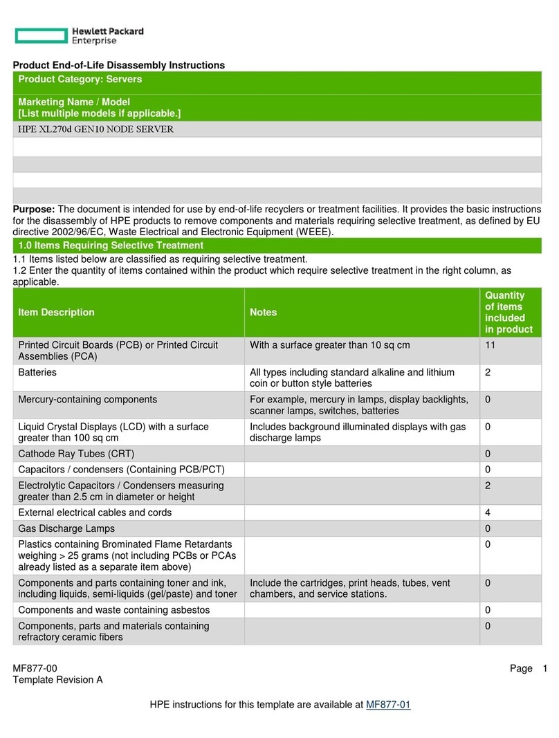
Blue Coat PacketShaper PS12000 Series Installation and operation manual

BETADRA
Blue Coat® PacketShaper
Maintenance and Upgrade
Guide
PS12000 Series
Document Number: 231-03152 Rev B.0

Disclaimer
THIS DOCUMENT IS PROVIDED “AS IS” WITHOUT ANY EXPRESS OR IMPLIED WARRANTY OF ANY KIND, INCLUDING WARRANTIES OF MERCHANT-
ABILITY, NONINFRINGEMENT OF INTELLECTUAL PROPERTY, OR FITNESS FOR ANY PARTICULAR PURPOSE. IN NO EVENT SHALL BLUE COAT OR ITS
SUPPLIERS BE LIABLE FOR ANY DAMAGES WHATSOEVER (INCLUDING, WITHOUT LIMITATION, DAMAGES FOR LOSS OF PROFITS, BUSINESS INTER-
RUPTION, OR LOSSOF INFORMATION) ARISING OUT OF THE USE OFOR INABILITY TO USETHIS DOCUMENT, OR THE PRODUCTS DESCRIBEDHEREIN,
EVEN IF BLUE COAT HAS BEEN ADVISED OF THE POSSIBILITY OF SUCH DAMAGES. BECAUSE SOME JURISDICTIONS PROHIBIT THE EXCLUSION OR
LIMITATION OF LIABILITY FOR CONSEQUENTIAL OR INCIDENTAL DAMAGES, THE ABOVE LIMITATION MAY NOT APPLY TO YOU. Blue Coat and its
suppliers further do not warrant the accuracy or completeness of the information, text, graphics, links or other items contained within this
document, or assume liability for any incidental, indirect, special or consequential damages in connection with the furnishing, performance,
or use of this document. Blue Coat may make changes to this document, or to the products described herein, at any time without notice. Blue
Coat makes no commitment to update this document.
Copyrights / Trademarks / Patents
Copyright© 1999-2011 Blue Coat Systems, Inc. All rights reserved worldwide. No part of this document may
be reproduced by any means nor modified, decompiled, disassembled, published or distributed, in whole or
in part, or translated to any electronic medium or other means without the written consent of Blue Coat
Systems, Inc. All right, title and interest in and to the Software and documentation are and shall remain the
exclusive property of Blue Coat Systems, Inc. and its licensors. ProxyAV™, CacheOS™, SGOS™, SG™,
Spyware Interceptor™, Scope™, ProxyRA Connector™, ProxyRA Manager™, Remote Access™ and
MACH5™ are trademarks of Blue Coat Systems, Inc. and CacheFlow®, Blue Coat®, Accelerating The
Internet®, ProxySG®, WinProxy®, PacketShaper®, PacketShaper Xpress®, PolicyCenter®, PacketWise®,
AccessNow®, Ositis®, Powering Internet Management®, The Ultimate Internet Sharing Solution®,
Cerberian®, Permeo®, Permeo Technologies, Inc.®, and the Cerberian and Permeo logos are registered
trademarks of Blue Coat Systems, Inc. All other trademarks contained in this document and in the Software
are the property of their respective owners.
BLUE COAT SYSTEMS, INC. AND BLUE COAT SYSTEMS INTERNATIONAL SARL (COLLECTIVELY
“BLUE COAT”) DISCLAIM ALL WARRANTIES, CONDITIONS OR OTHER TERMS, EXPRESS OR
IMPLIED, STATUTORY OR OTHERWISE, ON SOFTWARE AND DOCUMENTATION FURNISHED
HEREUNDER INCLUDING WITHOUT LIMITATION THE WARRANTIES OF DESIGN,
MERCHANTABILITY OR FITNESS FOR A PARTICULAR PURPOSE AND NONINFRINGEMENT. IN NO
EVENT SHALL BLUE COAT, ITS SUPPLIERS OR ITS LICENSORS BE LIABLE FOR ANY DAMAGES,
WHETHER ARISING IN TORT, CONTRACT OR ANY OTHER LEGAL THEORY EVEN IF BLUE COAT
SYSTEMS, INC. HAS BEEN ADVISED OF THE POSSIBILITY OF SUCH DAMAGES.
Revision History
October, 2009 231-03152 Rev A.0
November, 2010 231-03152 Rev A.1
December 2010 231-03152 Rev A.2
March 2011 231-03152 Rev A.3
July 2011 231-03152 Rev B.0

PacketShaper 12000 Series Maintenance Guide 3
Table of Contents
About This Guide ..........................................................................................5
Safety Warnings and Cautions.................................................................................................................... 5
Power and Electrical Warnings ............................................................................................................5
System Access Warnings .......................................................................................................................6
Electrostatic Discharge (ESD) Warning............................................................................................. 6
PacketShaper 12000 Series System Diagram........................................................................................7
PacketShaper LEDs ..................................................................................................................................8
PacketShaper 12000 Input/Output Ports .............................................................................................11
PS12000 LAN Expansion Module ..............................................................13
Pre-Installation Checklist ............................................................................................................................13
LEM Card Listing ............................................................................................................................................14
Replacing the LEM Card Bracket (Optional).........................................................................................16
Installing a LEM Card....................................................................................................................................18
Replacing the Main Slot LEM Card ..........................................................................................................23
Verifying the LEM Installation ...................................................................................................................27
PS12000 Fan Assembly..............................................................................29
Pre-Installation Checklist ............................................................................................................................29
Identifying a Faulty Fan Assembly ..........................................................................................................30
Replacing the Fan Assembly .....................................................................................................................30
Verifying Fan Installation .....................................................................................................................33
PS12000 Hard Disk Drive ...........................................................................35
Pre-Installation Checklist ............................................................................................................................35
Identifying a Faulty Hard Disk Drive .......................................................................................................36
Replacing the Hard Disk Drive (HDD).....................................................................................................37
Verifying HDD Replacement...............................................................................................................39
PS12000 Power Supply Unit ......................................................................41
Pre-Installation Checklist ............................................................................................................................41
Identifying a Faulty Power Supply Unit (PSU).....................................................................................41

4 PacketShaper 12000 Series Maintenance Guide
Replacing the Power Supply Unit (PSU)................................................................................................42
Verifying Power Supply Replacement ...................................................................................................42
PS12000 Front Bezel...................................................................................43
Pre-Installation Checklist ............................................................................................................................43
Replacing the Bezel ......................................................................................................................................44

About This Guide
PacketShaper 12000 Series Maintenance Guide 5
About This Guide
The PacketShaper 12000 Series Maintenance Guide describes how to install field-serviceable
components in the PS12000 Series appliance.
Note: Review the “Safety Warnings and Cautions” before servicing your appliance.
Online Documentation
To download the latest version of this guide and other hardware documents, visit:
https://bto.bluecoat.com/documentation/pubs/PacketShaper
Safety Warnings and Cautions
!Caution: This product is designed to work with power systems having a grounded neutral. To reduce the risk
of electric shock, do not plug this product into any other type of power system. Contact a qualified
electrician if you are not sure what type of power is supplied to your building.
Power and Electrical Warnings
CAUTION
●The power button, indicated by the stand-by power marking, DOES NOT completely turn off the system AC power, 5V standby
power is active whenever the system is plugged in. To remove power from system, you must unplug the AC power cord from
the wall outlet. If your system uses more than one AC power cord, make sure all AC power cords are unplugged. before you
open the chassis, or add or remove any non hot-plug components.
●The power supply in this product contains no user-serviceable parts. Do not open the power supply. Hazardous voltage,
current and energy levels are present inside the power supply. Return to manufacturer for servicing.
●To avoid risk of electric shock, turn off the appliance and disconnect the power cord, telecommunications systems, networks,
and modems attached to the appliance before opening it.
●The power cord set included with the appliance meets the requirements for use in the country of purchase. Use the power
cord that shipped with the appliance. If this appliance is to be used in another country, purchase an AC power cord set that is
approved for use in that country (18 AWG recommended).
●The power cord must be rated for the product and for the voltage and current marked on the product's electrical ratings label.
The voltage and current rating of the cord should be greater than the voltage and current rating marked on the product. In
addition, the cross-sectional area of the wires must be a minimum of 1.00mmð or 18AWG or 18AWG, and the length of the
cords must be between 1.8m (6 feet) and 3.6m (12 feet).

About This Guide
6 PacketShaper 12000 Series Maintenance Guide
System Access Warnings
CAUTION
To avoid personal injury or property damage, the following safety instructions apply whenever accessing the inside of the
product:
●Turn off all peripheral devices connected to this product.
●Turn off the system by pressing the power button.
●Disconnect the AC power by unplugging all AC power cords from the system or wall outlet.
●Disconnect all cables and telecommunication lines that are connected to the system.
●Retain all screws or other fasteners when removing access cover(s). Upon completion of accessing the inside of the product,
refasten access cover with original screws or fasteners.
●Do not access the inside of the power supply. There are no serviceable parts in the power supply. Return to manufacturer for
servicing.
●Power down the appliance and disconnect all power cords before adding or replacing any non hot-plug component.
Electrostatic Discharge (ESD) Warning
CAUTION
ESD can damage disk drives, boards, and other parts. When servicing the appliance ensure that the appliance is grounded and
that the operator performs all procedures with an antistatic wrist strap that is grounded.
After removing a replaceable component from its protective wrapper, place the component on a grounded, static free surface.

About This Guide
PacketShaper 12000 Series Maintenance Guide 7
PacketShaper 12000 Series System Diagram
The following illustrations show the location of the replaceable components on the Blue Coat
PacketShaper 12000 Series appliance.
1
System HDD
Data HDD
Power Supply Units
System Fan Array
LEM (LAN Expansion Module) Slot
Main Slot
Bezel

About This Guide
8 PacketShaper 12000 Series Maintenance Guide
PacketShaper LEDs
The LEDs on the PS12000 series appliances display the health of the appliance and the status
of individual components.
The front-panel LED indicates power supply input, disk activity, interface activity, and system
status.
System fan LEDs are located on the system fan board inside the appliance. The failure of a
system fan triggers the fan failure LED, which is located on the system fan board inside the
chassis, and the system status LED, which is located on the front-panel of the appliance.
The rear panel includes the power supply adapter LED, which indicates proper functioning of
the power supply units and the ID LED that is used to locate the appliance when rack
mounted.
Front Panel LEDs Color Status
1. Power Blue System is operational
Blue: flickering System is in power saving state
Off System is powered off
2. ID
Press the ID button to illuminate the front and
back ID LEDs. The rear panel LED helps you to
easily identify this appliance when it is installed
in a rack with other appliances.
You can activate this LED using IPMI commands
too.
Off Not in use because the ID button has not
been pressed.
Amber Enabled (the ID button is activated)
3
5
1 2 DATA HDD
12
1 2 4

About This Guide
PacketShaper 12000 Series Maintenance Guide 9
3. Interface Blue Interface linked
Blue: blinking Network activity
Off No Link
4. System Fault Red Critical Fault (non-fatal faults [e.g. a
disconnected power cord] can also cause a
critical fault error; see the Alerts panel in
the Sky UI for more information)
Red: flickering System errors, non-fatal faults (e.g. a non-
critical threshold has been exceeded)
Off Healthy
5. Disk Blue Disk drive present
Blue: flickering Disk drive activity/data access
Red Disk drive fault
Off No disk drive present
Front Panel LEDs Color Status

About This Guide
10 PacketShaper 12000 Series Maintenance Guide
Rear Panel LEDs Color Status
1. AC Power Green Powered on and operational
Green: flickering 5V standby power is present on the
appliance
Amber Power supply unit failure, or one of the two
power supply units is not connected to an
AC power source.
Amber: flickering Warning event for any of the following
conditions: high temperature, high
current, high power, slow fan
Off No AC power to the power supply unit
2. ID Blue On
This rear panel LED helps you to easily
identify this appliance when it is installed
in a rack with other appliances
Off Identification feature is not in use
21

About This Guide
PacketShaper 12000 Series Maintenance Guide 11
PacketShaper 12000 Input/Output Ports
PacketShaper 12000 appliances feature a complement of input/output ports. The available
ports are described below.
Rear Panel Ports Port information
1. Standby port Onboard 10/100/1000 Base-T interface for use w/direct standby feature
2. Inside port 10/100/1000 Base-T interface pass-through interface
3. Outside port 10/100/1000 Base-T interface pass-through interface
4. Management port Onboard 10/100/1000 Base-T interface
5. Keyboard port Non-operational
6. Mouse port Non-operational
7. Display port Non-operational
8. Serial port DB9 serial port used to connect the PS12000 to a PC or serial terminal
9. Power supply inlet 2 3 - prong electrical inlet
10. Power supply inlet 1 3 - prong electrical inlet
10
9
8
7
6
5
4
123

About This Guide
12 PacketShaper 12000 Series Maintenance Guide

PacketShaper 12000 Series Maintenance Guide 13
PS12000 LAN Expansion Module
This section describes how to install upgrade/replacement LAN expansion modules (LEM) for
the PacketShaper 12000 Series appliance.
The PacketShaper 12000 Series appliance is equipped with two PCI slots on a riser card: the
LEM (LAN expansion module) slot and the main slot. The LEM supports full-height PCI-E
expansion cards; while the main slot supports a low-profile PCI-E card, which accommodates
the included dual-port (single bridge) Ethernet Gigabit copper card. You can replace this card
with an optional LEM, depending on your deployment requirements.
The diagram below shows the location of the expansion slots:
Pre-Installation Checklist
Item Description
Tools Required Phillips head screwdriver
Components Supplied Upgrade / replacement network card
Safety Notices Read “Safety Warnings and Cautions” on page 5
LEM (LAN Expansion Module) Slot
Main Slot*
*The PS12000 comes equipped with a dual-port (single bridge) 1000BaseT card in the main PCI slot.

14 PacketShaper 12000 Series Maintenance Guide
PS12000 LAN Expansion Module
LEM Card Listing
The table below lists the available LEM cards for the PS12000 Series appliance and their
requirements. A low-profile dual-port card replaces the existing Gigabit card found in the
main slot (the left-most expansion slot when looking from the rear). The full-height four-port
expansion cards can only be installed into the LEM slot due to the size of the card.
Network Card Description Expansion Slot Usage Additional
Requirements
LEM-PS12000-2GigE-CU Dual-port module:
10/100/1000BASE-T Copper LEM
(1 Bridge)
*The PS12000 comes equipped
with this card in the main slot.
Main slot (low-profile, replaces
existing card)
None
LEM-PS12000-2GigE-SX Dual-port module: 1000BASE-SX
Fiber-Optic LEM (1 Bridge)
None
LEM-PS12000-2GigE-LX Dual-port module: 1000BASE-LX
Fiber-Optic LEM (1 Bridge)
Requires
PacketWise8.7.1
or higher
LEM-PS12000-10G-CX-LP Dual-port module: 10GBASE-CX4
Copper LEM (1 Bridge)
None
LEM-PS12000-4GigE-CU Four-port module:
10/100/1000BASE-T Copper LEM
(2 Bridges)
LEM slot (full-height)
None
LEM-PS12000-4GigE-SX Four-port module: 1000BASE-SX
Fiber-Optic LEM (2 Bridges)
None
LEM-PS12000-4GigE-LX Four-port module: 1000BASE-LX
Fiber-Optic LEM (2 Bridges)
Requires
PacketWise8.7.1
or higher
LEM-PS12000-10G-CX-FP Dual-port module: 10GBASE-CX4
Copper LEM (1 Bridge)
None

PacketShaper 12000 Series Maintenance Guide 15
PS12000 LAN Expansion Module
Next: • If you are installing a full-height network card into your appliance, see “Installing a LEM
Card” on page 18.
• If you are installing a low-profile network card into your appliance, see “Replacing the Main
Slot LEM Card” on page 23.
LEM-PS12000-10G-SR Dual-port module: 10GBASE-SR
Fiber-Optic LEM (1 Bridge)
LEM or main slot (using the included
low-profile bracket,
see“Replacing the LEM
Card Bracket
(Optional)” on page
16 for more information.)
Requires
PacketWise8.7.1
or higher
LEM-PS12000-10G-LR Dual-port module: 10GBASE-LR
Fiber-Optic LEM (1 Bridge)
LEM or main slot (using the included
low-profile bracket,
see“Replacing the LEM
Card Bracket
(Optional)” on page
16 for more information.)
Requires
PacketWise8.7.1
or higher
Network Card Description Expansion Slot Usage Additional
Requirements

16 PacketShaper 12000 Series Maintenance Guide
PS12000 LAN Expansion Module
Replacing the LEM Card Bracket (Optional)
If your LEM (LAN expansion module) includes the optional low-profile bracket, the card can be
installed into either the LEM (full-height) or main (low-profile) slots. These LEM cards come
with the full-height bracket preinstalled onto the circuit board. If you want to install the LEM
into main, you must first replace the bracket with the optional low-profile bracket.
To replace the full-height bracket with the included optional low-profile bracket:
1. Carefully remove two (2) bracket screws from the LEM card.
Note: Be careful when removing the bracket screws from the LEM card. Scratches or nicks
on the circuit board can destroy the card!
*The LEM card is in the upside down position.

PacketShaper 12000 Series Maintenance Guide 17
PS12000 LAN Expansion Module
2. Install the low-profile LEM card bracket using the same Phillips head screws that were
removed in the previous step.
Next: • If you are installing a full-height network card into your appliance, see “Installing a LEM
Card” on page 18.
• If you are installing a low-profile network card into your appliance, see “Replacing the Main
Slot LEM Card” on page 23.
*The LEM card is in the right side up position.

18 PacketShaper 12000 Series Maintenance Guide
PS12000 LAN Expansion Module
Installing a LEM Card
To install or replace a full-height LEM card in a PacketShaper 12000 Series appliance:
1. Power off the appliance and disconnect both power cords. Unplug the power cords from
the AC power outlet and then from the appliance.
2. Remove the rear top cover.
a. Remove the screw on the top cover.
b. Slide and lift the top cover off the appliance by pressing the blue button and sliding
the top cover towards the rear of the appliance. After it slides out about an inch, lift
the cover off the chassis.
12
SystemDrive
a
b

PacketShaper 12000 Series Maintenance Guide 19
PS12000 LAN Expansion Module
3. Carefully remove the PCI riser card assembly.
a. Loosen the thumbscrews.
b. Unlock the release clips
c. Lift the PCI riser card assembly out of the appliance.
4. Unlock the securing tab and remove the dummy expansion slot cover. Set the expansion
slot cover aside in a safe location for future use.
a
b
c
Expansion slot cover

20 PacketShaper 12000 Series Maintenance Guide
PS12000 LAN Expansion Module
5. Insert the new card by holding the edges of the card and gently inserting into the LEM
slot. It might be necessary to lightly rock the LEM card into position. Verify that the PCI
card has been fully seated and is aligned with the riser card bracket.
6. Lock the securing latch. Verify that it is fully closed.
Table of contents
