4
SYSTE REQUIRE ENTS
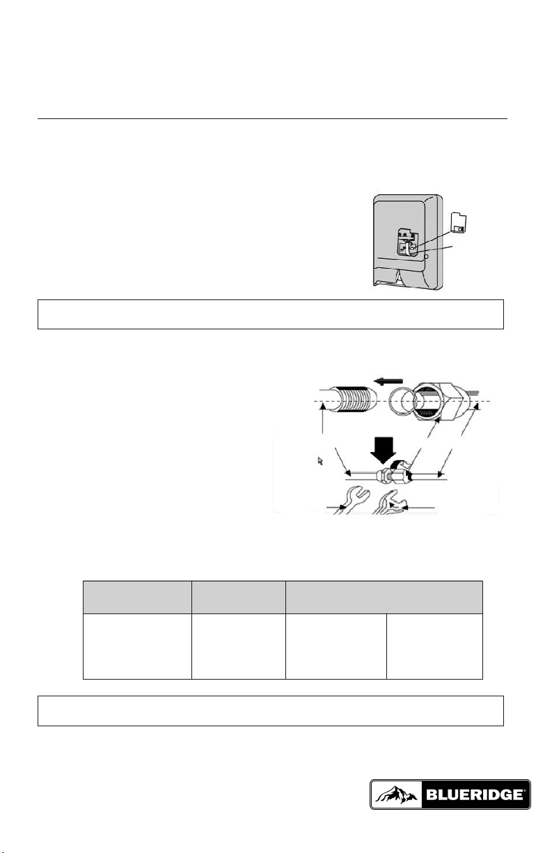
Piping Requirements
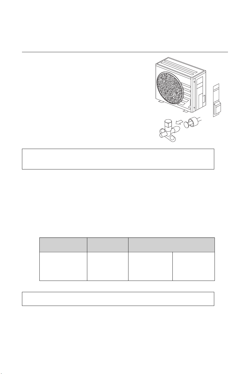
REFRIGERANT CHARGE
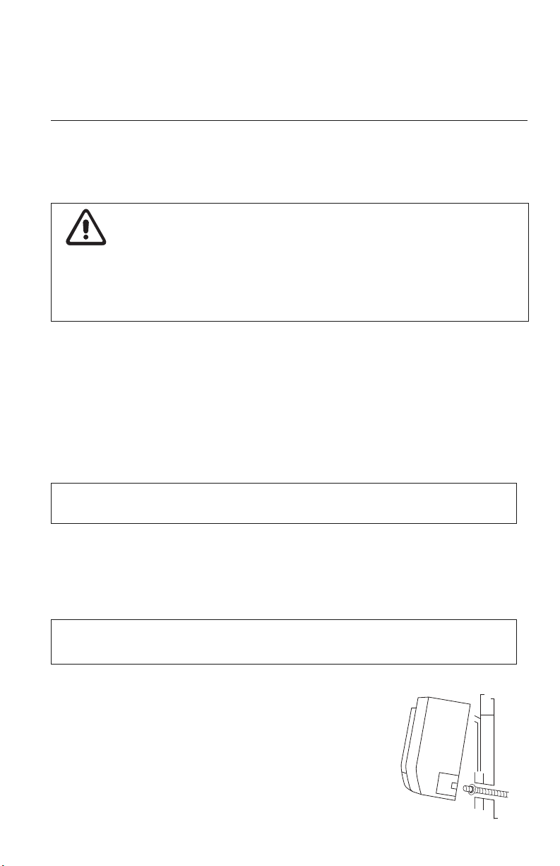
ELECTRICAL REQUIRE ENTS
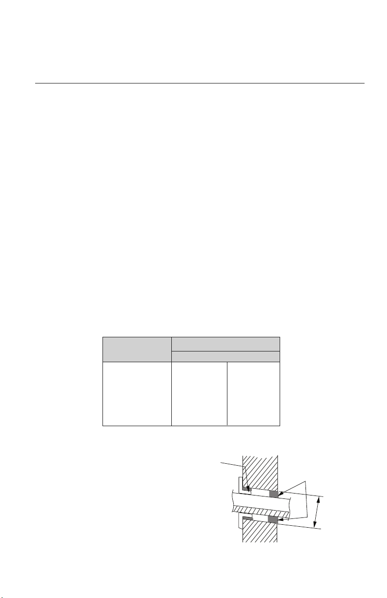
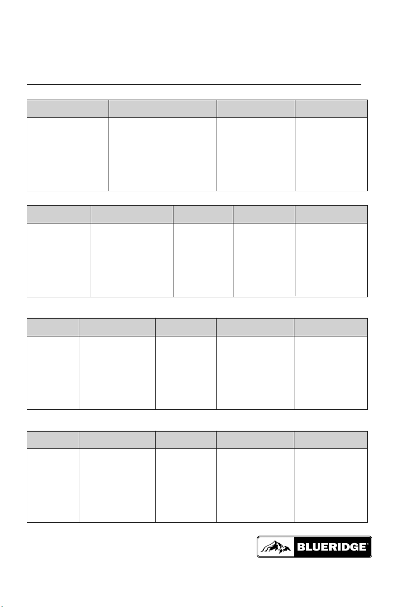
PIPE SIZE in (mm)
Notes: Insulate both refrigerant lines, separately.
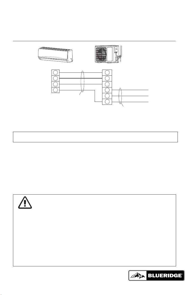
Notes: 1) System must be on a single dedicated circuit.
2) Main power is supplied to the outdoor unit.
3) Use table above to size over current protection.
4) Follow all local building codes and NEC (National Electrical Code) regulations.
Interconnecting Cable: Recommended cable - 14/4 AWG stranded bare copper conductors THHN 600V unshielded wire
Note: Use shield cable if installation is in close proximity of RF and EMI transmitting devices.
Condensate Drain Size: 5/8-in OD 7/16-in ID
Note: Insulate condensate drain hose to prevent sweating and possible water damage.
Unit Size Voltage Liquid Line Suction/Gas Line
(BtuH)
9,000 115v - 1ph 60hz 1/4 (6) 3/8 (9.5)
12,000 115v - 1ph 60hz 1/4 (6) 3/8 (9.5)
9,000 208/230v - 1ph 60hz 1/4 (6) 3/8 (9.5)
12,000 208/230v - 1ph 60hz 1/4 (6) 3/8 (9.5)
18,000 208/230v - 1ph 60hz 1/4 (6) 1/2 (12)
24,000 208/230v - 1ph 60hz 1/4 (6) 5/8 (16)
30,000 208/230v - 1ph 60hz 1/4 (6) 5/8 (16)
36,000 208/230v - 1ph 60hz 1/4 (6) 5/8 (16)
Unit Size Voltage in Line ax Line ax Elevation
(BtuH) Length Length (ID over OD)
9,000 115v - 1ph 60hz 10 (3) 50 (15) 33 (10)
12,000 115v - 1ph 60hz 10 (3) 50 (15) 33 (10)
9,000 208/230v - 1ph 60hz 10 (3) 50 (15) 33 (10)
12,000 208/230v - 1ph 60hz 10 (3) 66 (20) 33 (10)
18,000 208/230v - 1ph 60hz 10 (3) 82 (25) 33 (10)
24,000 208/230v - 1ph 60hz 10 (3) 82 (25) 33 (10)
30,000 208/230v - 1ph 60hz 10 (3) 100 (30) 33 (10)
36,000 208/230v - 1ph 60hz 10 (3) 100 (30) 33 (10)
Unit Size Voltage Refrigerant Factory System Additional
(BtuH) Type Charge oz (kg)* Charge oz/ft (g/m)
9,000 115v - 1ph 60hz R410A 42.9 (1.2) 0.2 (20)
12,000 115v - 1ph 60hz R410A 46.4 (1.3) 0.2 (20)
9,000 208/230v - 1ph 60hz R410A 46.4 (1.3) 0.2 (20)
12,000 208/230v - 1ph 60hz R410A 46.4 (1.3) 0.2 (20)
18,000 208/230v - 1ph 60hz R410A 49.4 (1.4) 0.2 (20)
24,000 208/230v - 1ph 60hz R410A 56.5 (1.6) 0.5 (50)
30,000 208/230v - 1ph 60hz R410A 84.7 (2.4) 0.5 (50)
36,000 208/230v - 1ph 60hz R410A 91.7 (2.6) 0.5 (50)
Unit Size Voltage in Circuit ax Overcurrent ain Power
(BtuH) Amps ( CA) Protection ( OP) Wire Size (AWG)**
9,000 115v - 1ph 60hz 22 35 10
12,000 115v - 1ph 60hz 23 40 10
9,000 208/230v - 1ph 60hz 10 15 14
12,000 208/230v - 1ph 60hz 10 15 14
18,000 208/230v - 1ph 60hz 13 20 12
24,000 208/230v - 1ph 60hz 16 25 10
30,000 208/230v - 1ph 60hz 20 30 10
36,000 208/230v - 1ph 60hz 24 40 10
**Main power wire from electrical panel to outdoor unit.
*Precharge amount for up to 25-ft of refrigerant pipe.
REFRIGERANT LINE LENGTHS ft (m)