Bluebird Micro Bird User manual


MICRO - BIRD
1
TABLE OF CONTENTS
Reporting Safety Defects .................................................................. 3
Foreward ............................................................................................. 4
Bus Body Identification..................................................................... 5
Daily Check List ................................................................................. 6
Quarterly Maintenance Check List ................................................. 8
Annual Maintenance Check List ..................................................... 8
Switch Panel ....................................................................................... 9
Seats & Seat Belts ............................................................................. 10
Driver's Seat Belt Operation ...................................................... 10
Passenger Seat Belt Operation .................................................. 10
Seat Belt Inspection & Maintenance......................................... 10
Seat Cushion Removal & Installation ...................................... 11
Mirror & Mirror Adjustment ......................................................... 12
Inside Mirrors.............................................................................. 12
8" Dia. Supplemental Rearview Mirror ................................... 13
Outside Mirrors........................................................................... 13
Emergency Equipment ................................................................... 16
Warning Device Positioning ..................................................... 16
Emergency Exits............................................................................... 17
Stop Arms ......................................................................................... 18
Heaters .............................................................................................. 18
General Information ................................................................... 18
Heater Operation ........................................................................ 19
Defrosting .................................................................................... 20
Heater Hose Clamp Service ...................................................... 21
Heater Bleeding Instructions .................................................... 22
Circuit Breakers................................................................................ 23
Light Bulb Data ................................................................................ 24

MICRO - BIRD
2
Normal Curent Usage ..................................................................... 25
Standard Equipment .................................................................. 25
Optional Equipment................................................................... 26
Visibility Equipment Required ...................................................... 28
Preventive Maintenance Check List.............................................. 30
Glass Replacement........................................................................... 32
Split Sash ...................................................................................... 32
Rear Vision................................................................................... 34
Entrance Door ............................................................................. 34
Doors ................................................................................................. 35
Door Control Maintenance & Adjustment.............................. 35
Lubrication - Windows, Hinges & Locks ..................................... 36
Floor Covering ................................................................................. 37
Destination Signs ............................................................................. 37
Drain Holes...................................................................................... 37
Keeping Your Vehicle Looking New ............................................ 38
Jacking Instructions ......................................................................... 39
Index .................................................................................................. 40

MICRO - BIRD
3
REPORTING SAFETY DEFECTS
If you believe your vehicle has a safety defect which could
cause injury or death, you should immediately inform the Na-
tional Highway Traffic Safety Administration (NHTSA) in addi-
tion to notifying Blue Bird Body Company.
If NHTSA receives similar complaints, it may open an inves-
tigation, and if it finds that a safety defect exists in a group of
vehicles, it may order a recall and remedy campaign. However,
NHTSA cannot become involved in individual problems between
you, your dealer, or Blue Bird Body Company.
To contact NHTSA, you may either call the Auto Safety
Hotlinetoll freeat 1-800-424-9393(or 366-0123in WashingtonD.C.
area). Or write to: NHTSA, U.S. Department of Transportation,
Washington D.C. 20590. You can also obtain other information
about Motor Vehicle Safety from the hotline.

MICRO - BIRD
4
FORWARD
This Operator’s Manual provides some general, as well as
specific information regarding safe operation and maintenance of
your Blue Bird bus. It does not address all items or situations that
may arise and is not a substitute for proper driver and mechanic
training. The exercise of care, common sense, and good driver and
working practices are required for safe operation.
If specific questions or concerns arise that are not adequately
addressedinthismanualpleasecontactyourBlueBirddistributor.
The distributor will answer your questions or put you in contact
with the proper factory personnel. Throughout this guide, you
will find CAUTIONS and WARNINGS. WARNINGS remind
you to be especially careful to avoid personal injury. CAUTIONS
are given to prevent you from making an error which could
damage the vehicle and possibly cause personal injury.
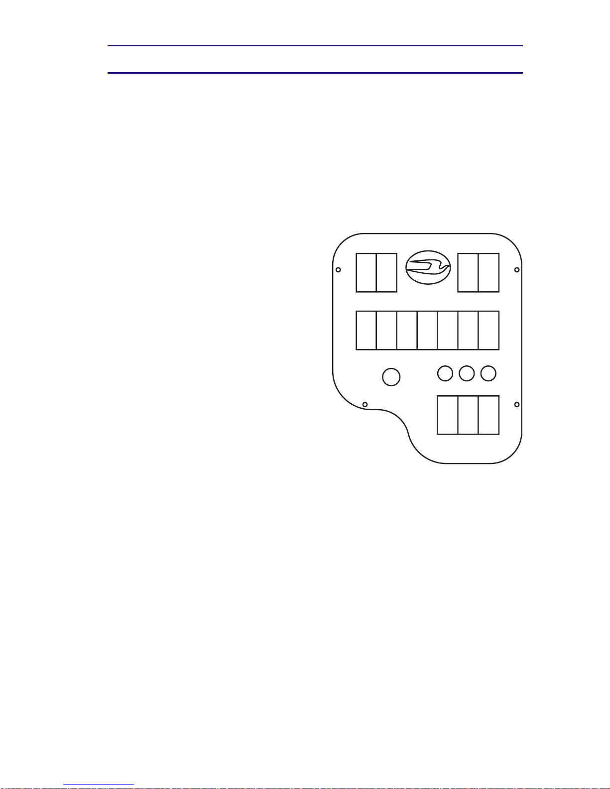
Blue Bird Body Company offers many items as standard and
optional equipment to insure reliable and safe transportation of
passengers.
Some examples of this safety equipment are: stop arms,
crossing guards, warning lights, warning light monitors, mirrors,
first aid kits, fire extinguishers, warning reflectors, fusees, direc-
tional and brake lights, warning buzzers, vandal locks, emergency
exits, and seat belts.
It is the drivers responsibility to insure that the safety items
are in proper order. Equipment relating to should be checked for
operation on a daily basis. Safety equipment may vary due to state
and federal specifications.
In addition, the driver/operator must insure that the loading
areaaroundthebusisclearofpedestriansbeforestoppingandthat
all unloaded passengers are a safe distance away from the bus
before moving.
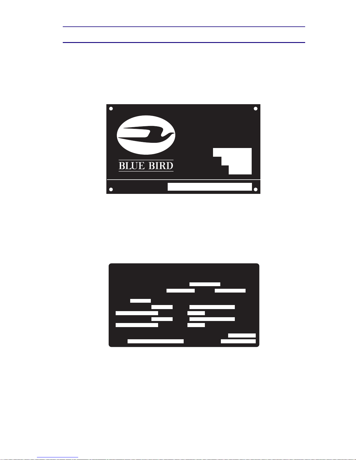
Blue Bird has mounted the bus body on the chassis you have
received. You should have also received an operator’s manual
with your vehicle from the chassis manufacturer. If you have
failed to receive such a manual, contact the chassis manufacturer’s
closest dealership to obtain one. Please read this manual and the
chassis manual carefully before operating or repairing your bus.

MICRO - BIRD
5
BODY IDENTIFICATION
The Body Serial Number Plate and Body Service Number
Plateare located above the windshield on the right side of the unit.
Refer to the data on these plates for registration purposes or for
replacement part information.
BLUE BIRD
BODY CO.
FORT VALLEY, GEORGIA
BODY NO.
CAPACITY
MODEL YEAR
BODY SERVICE NO.
The Vehicle Certification Plate certifies that the vehicle con-
forms to all applicable Federal Motor Vehicle Safety Standards in
effect at the date of manufacture. Do not remove or deface this
plate. This plate is located over the drivers window.
MANUFACTURED BY
BLUE BIRD BODY COMPANY
DATE OF MFR.
INC. VEH. MFG. BY DATE
SUITABLE TIRE - RIM CHOICE
GVWR
GAWR : FRONT
GAWR : REAR WITH TIRES
PSI COLD SINGLE
PSI COLD DUAL
WITH TIRES
RIMS, AT
RIMS, AT
THIS VEHICLE CONFORMS TO ALL APPLICABLE FEDERAL
MOTOR VEHICLE SAFETY STANDARDS IN EFFECT IN
CLASSIFICATION
V.I.N.

MICRO - BIRD
6
DAILY CHECK LIST
In order to keep your bus in the best operating condition from
the standpoint of safety, convenience, service, and operating ex-
pense, it is recommended the following inspection procedures be
followed on a daily basis. Any malfunctions or defects should be
corrected before the next trip. Report needed services to respon-
sible maintenance personnel.
Look outside the bus:
* Windshield, mirrors, front windows, headlights - wipe clean.
* Exhaust - tailpipe clear?
* Bump tires OK? Lug nuts in place?
* Drain air brake tanks.
* Look under bus - all clear?
* General outside appearance, clean for school bus identifica-
tion?
* Mirrors, clean and adjusted?
Look inside the bus:
* Seat, floor - housekeeping.
* Emergency exits open & close, side door, windows.
* Emergency equipment.
* Fire extinguisher pressure.
* First aid kit.
* Driver’s area - windshield, windows, clean?
* Mirrors - clean and adjusted?
Starting the engine:
* Make sure the emergency brakes are on.
* Put in Neutral.
* Fuel gauge OK? Check brake warning buzzer or light, neu-
tral safety switch.
* Start engine - look, listen for trouble signs, check gauges

MICRO - BIRD
7
With the engine running, check (from driver’s seat):
* Mirrors, interior and stepwell lights, service door seal.
* Steering feel OK? Noise?
* Horn, defroster and heater blower, windshield wiper
operation.
* Brakes - pedal height and feel, gauge reading OK? Parking
brake release, reset.
Outside checks required before you drive away:
* Turn signals - right and left, front and rear - clean and
flashing?
* Flasher warning lights - front and rear - clean and flashing?
* Stop arm (if used) - clean and working?
* Headlights hi-lo beams.
* Stoplights and taillights - clean and working?
* Hazard flasher working?
Final check as you move the bus:
* Seat belt fastened?
* Brakes. Stop and hold?
* Steering feel OK? Unusual noises? Bus under control -
tracking straight?
* Brake to a stop. All gauges OK?
Remember: Safetyon theroad alsodepends onyou. Observe
weather and road conditions and drive according. Be physically
and mentally alert. Look around before driving away from where
you are parked and observe all traffic rules and regulations.

MICRO - BIRD
8
QUARTERLY
MAINTENANCE CHECK LIST
* Inspect fire extinguisher to see if fully charged.
* Check first aid kits to see if fully equipped.
* Oil all hinges and window latches for ease of operation.
* Lubricate all window channels with silicone or graphite.
* There is one drain hole in each floor section under windows.
* Be sure hole is clear of debris so any water may escape.
* Clean all rubber door seal and lubricate with rubber
lubricant.
* All rear and side emergency door latch slide bars to be
lubricated with light grease to reduce friction.
* Tighten all body tie down bolts to 38 foot pounds torque at
1,000 miles, 2,000 miles, and quarterly thereafter.
* Grease emergency door hinges.
ANNUAL
MAINTENANCE CHECK LIST
* Complete Quarterly Maintenance Check List.
* Remove all seat cushions, thoroughly clean with upholstery
cleaner, and reinstall on a rotating basis.
* Adjust door control rod and closing mechanism to entrance
doors.
* Thoroughly clean all front heater cores.
* Bleed all air from heaters.
* Tighten all heater hose clamps.
Note: These check lists are suggested. They do not replace or
supersede local or state required driver inspection procedure.

MICRO - BIRD
9
SWITCH PANEL
1. Manual warning light switch.
2. Master warning light switch. Systems may vary on some
units.
3. Warning light switch emergency override.
4. Emergency exit or lift pilot.
5. Pilot - shows amber warning lights are flashing.
6. Pilot - shows red warning lights are flashing.
7. Pilot - Warning light monitor.
8. Clearance lamps.
9. Dome lights.
10. Underseat heater.
11. Heater pump.
12. Mirror defrost.
13. Auxiliary fan.
14. Strobe Light.
15. Destination sign.
16. Lift.
17. Stop arm / Crossing arm.
18. Switch panel rheostat.
Note: Positions 8-18. Components are located in order of
dominance. Depending on unit equipped features.
Note: Driver's compartment not indicated. Located above
driver's side door, accessible by depressing release button latches.
MICRO BIRD
123
12 13 14
17 1815 16
8910
567
4
11

MICRO - BIRD
10
SEATS & SEAT BELTS
DRIVER’S SEAT BELT OPERATION
For driver’s seat belt operation refer to chassis manual. if you
failed to receive such a manual, contact the chassis manufacturer’s
closest dealership immediately to obtain one.
PASSENGER SEAT BELT OPERATION IF SO EQUIPPED
Individual lap belts for passengers are of the non-retracting
design. Insert the catch into the buckle, test for the assurance of a
latchfit,andpullthelooseendofthe buckle-endstrapuntilthebelt
fits snugly across the lower hips. The buckle can be released
depending on the buckle type, by either lifting the outboard edge,
or by pushing button in the center of buckle. The adjustable end
can be moved outward on its strap by turning 90 degrees to the
strap and pulling.
SEAT BELT INSPECTION AND MAINTENANCE
Inspect seat belt assembly frequently. Anytime assembly
does not work properly, or if there are any defects in the webbing
(i.e. torn or frayed), the seat belt must be replaced as soon as
possible to insure passenger safety.
Hand wash webbing with warm water and mild soap. Rinse
thoroughly and dry in the shade. Do not bleach or redye, because
such processing may severely weaken the assembly.
WARNING: Be sure the lap belt is fitted snugly across the
hips, not the waist. Failure to do so may increase the chance of
injury in the event of a collision.
WARNING: If seat cushions are removed for maintenance,
they must be installed using the following instructions. Failure
to comply with these instructions could result in injury from
unattached seat cushions in the event of an accident.
SEAT CUSHION REMOVAL & INSTALLATION - DOT
SEATS
Removal
1. Loosen the two front swivel type clamps at the front under-
side of the cushion with a phillips type screw driver.
Caution - Do not remove clamps.

MICRO - BIRD
11
2. Rotate the swivel clamps so as to clear the front retaining
channel frame.
3. Lift the forward edge of the cushion 2 to 3 inches and pull
cushion forward to remove.
Installation
1. Place the rear edge of the cushion down on the base portion
of the seat frame. Lifting the forward edge of the seat frame 2
to 3 inches, slide the cushion to the rear to engage the positive
type clamp into the rear retaining channel.
2. Lower the forward edge to the frame making sure the swivel
clamps are inside the frame and the positive type clamps are
secure on the rear retaining channel.
3. Rotate the swivel clamp to engage the forward retaining
channel frame.
4. Tighten with phillips type screw driver until clamps do not
rotate.
SEAT CUSHION REMOVAL & INSTALLATION - DOT
SEAT BELT SEATS
Removal
1. Loosen the two front swivel type clamps at the front under-
side of the cushion with a phillips type screw driver.
Caution - Do not remove clamps.
2. Rotate the swivel clamp located at the rear underside of the
seat cushion.
3. While lifting at the rear edge of the cushion, pull the cushion
to the rear and remove.
Installation
1. Placethe forwardedgeofthe cushion2inchesto therearofthe
front retaining clamps. Slide the cushion forward engaging
the positive clamps onto the forward retaining channel.
2. Lower the rear edge of the frame and rotate the swivel clamps
so they engage the square tube crossmember.
3. Tighten with phillips type screw driver until clamps do not
rotate.

MICRO - BIRD
12
MIRRORS & MIRROR ADJUSTMENTS
WARNING: The vehicle's mirror system has been designed
to comply with all field of view requirements, but it is the
owner's responsibility to adjust the mirrors properly before plac-
ing the vehicle in service and to maintain the adjustment dur-
ing the service life of the vehicle. Mirrors provide additional
driver visibility on buses. To be effectively used mirrors must
be properly adjusted for each driver and the driver must be aware
of the limitations on the viewing area that exists even when the
mirrors are properly used. Mirrors are not a substitute for proper
driver training and the exercise of driver care in operating the
vehicle and loading and unloading passengers.
WARNING: Do not move the bus until you have accounted
for each passenger that has disembarked and have confirmed
that the passenger of the bus. Failure to follow these proce-
dures could cause serious injury or death.
Leftandrightfrontfendermountedconvexcrossviewandleft
and right front fender mounted rearview mirrors are required
equipment on all Micro-Bird, Type (A), buses.
INSIDE MIRRORS
Inside rearview mirrors are adjustable by loosening the bolts
and nuts in slotted holes. Adjust the mirror to afford the operator
a good view of bus interior and roadway to the rear.
WARNING: Many school bus passengers are energetic chil-
dren who are small and playful and do not understand the haz-
ards of buses. After unloading, some children could be outside
the field of vision of your mirrors or could quickly dart into
such a place. Do not move your bus after unloading passengers
until you have confirmed the location of every child who got
off and have confirmed that each child is completely clear of
the bus. Failure to follow this procedure could cause serious
injury or death.

MICRO - BIRD
13
8" DIA. SUPPLEMENTAL OUTSIDE REARVIEW MIRROR
Some units may be equipped with two (2) 8" elliptical mirrors,
one on the LH side and one on the RH side, which are designed to
supplement the view provided by the outside rearview driving
mirrors. The RH 8" elliptical mirror is attached to the RH outside
rearview mirror mounting bracket as illustrated, and is viewed
through the RH windshield. The LH 8" elliptical mirror is attached
to the bus body and is located so as to be viewed through the LH
windshield.
Proper adjustment is necessary for any mirror system to
perform as designed. The following adjustment should be used
to allow the driver to obtain the maximum viewing area with the
mirror system.
Position the RH 8" elliptical mirror in the location illustrated.
Adjust the 8" elliptical mirrors on both the RH and LH side to
provide the seated driver a view of the ground directly below the
outside rearview driving mirrors, and rearward to overlap the view
provided by the outside rearview convex driving mirrors.
CAUTION: A convex mirror has a curved surface and is de-
signed to provide a wide view with minimum distortion. How-
ever, persons or objects seen in a convex mirror will look smaller
and appear farther away than when seen in a flat mirror or
viewed directly. Therefore, use care when judging the size or
distance of a person or object seen in a convex mirror. Wait until
you can view the person or object in a flat mirror or direct view
to determine their size and distance.
OUTSIDE REARVIEW
Standard equipment on all school buses is comprised of 4
outside rearview driving mirrors. (2 per side), and 2 elliptical
crossview mirrors, (1 per side). The outside rearview driving
mirrors include (1) 6.5"x 10" flat mirror and (1) 6.5"x10" convex
mirror each side. The outside rearview driving mirrors are
designed to provide the seated driver a view of the roadway to
the rear and to the sides of the bus. The elliptical crossview mirrors
are designed to provide a seated driver a view of all areas around
the front of the bus not directly visible to the driver. The elliptical
crossview mirrors are designed to be used to view pedestrians
while bus is stopped.

MICRO - BIRD
14
DO NOT USE THE ELLIPTICAL CROSSVIEW MIRRORS TO
VIEW TRAFFIC WHILE BUS IS MOVING. AS IMAGES IN
SUCH MIRRORS DO NOT ACCURATELY SHOW ANOTHER
VEHICLE’S LOCATION.
Proper adjustment is necessary for any mirror system to
perform as designed. The following adjustment sequence should
be used to allow the driver to obtain the maximum viewing area
with the mirror system.
1. Adjust the driver’s seat to the desired position.
2. Adjust the RH flat driving mirror so that the tops of the side
windows are visible in the upper edge of the mirror, and so
that the RH side of the bus body is visible in the inside edge
of the RH flat mirror.
3. Adjust the RH convex driving mirror so that the view in the
top of the convex mirror overlaps the view provided by the
RH flat driving mirror, and so that the RH side of the bus
body is visible in the inside edge of the RH convex mirror.
4. Adjust the LH flat driving mirror and the LH convex driving
mirror following the same procedures described for the RH
mirrors. Refer to steps #2 and #3 above.
5. Adjust the elliptical crossview mirrors by positioning each
mirror head so that the “arrow” embossed in the top of the
elliptical mirror housing is pointed directly at the eyes of the
seated driver.
6. A final adjustment should be made to the mirror system so
that the seated driver can view the areas required by FMVSS
111, including the entire top surface of cylinders M and N
(when located as illustrated and rearward a minimum of 200
feet (measured from the mirror surface) using the outside
rearview driving mirrors. The elliptical crossview mirrors
should be adjusted to provide the seated driver a view of the

MICRO - BIRD
15
entire surface of any cylinder A thru P (when located as
illustrated) not visible by direct view of the driver. The view
provided by the elliptical crossview mirrors must overlap the
view provided by the outside rearview driving mirror system.
12 FEET FROM
FRONTBUMPER
6 FEET FROM
FRONTBUMPER
FACE OF
FRONTBUMPER
CENTERLINE
FRONTAXLE
OUTSIDE OF
BUMPER
OUTSIDE OF
BUMPER
CENTERLINE
OF BODY
CENTERLINE
REAR AXLE
6 FEET FROM
OUTSIDE BODY
1 FOOT FROM
OUTSIDE BODY
1 FOOT FROM
OUTSIDE BODY
6 FEET FROM
OUTSIDE BODY
12 FEET FROM
OUTSIDE BODY
- TEST CYLINDER
TEST CYLINDERS A-O ARE
1 FOOT HIGH X 1 FOOTDIAMETER
CYLINDER P IS
3 FEET HIGH X 1 FOOT DIAMETER
A B C
F
E
D
I
H
G
JK
MN
LO P
FRONT
OF BUS

MICRO - BIRD
16
EMERGENCY EQUIPMENT
The fire extinguisher is located
in the right front corner of the bus
body near the floor. Your unit may
be equipped with a 2-1/2, 5 or 6
pound extinguisher. Check quar-
terlytomake sureitisfully charged.
If your unit is supplied with
triangularreflectorsandfusees,they
are located to the left of the driver’s
seat.The first aid kit is mounted above the windshield on the right
hand side of the bus body. Different size kits are supplied in
various bodies because of different state specifications. Check
quarterly to see if fully equipped.
RECOMMENDED WARNING DEVICE POSITIONING
100 Feet
Approximately 40 Paces
100 Feet
Approximately 40 Paces
Approximately 80 PacesApproximately 40 Paces
200 Feet100 Feet
Disabled
Unit
Disabled
Unit
Front
Rear
Two Lane Traffic
Front
Rear
Four Lane Traffic
Start 10 Feet
From Rear of Bus
Start 10 Feet
From Rear of Bus

MICRO - BIRD
17
EMERGENCY EXITS
Emergency exits are clearly identified by the words “Emer-
gency Exit”. Operating instructions are written close to each exit.
Some units are equipped with an audible alarm device signifying
an emergency exit is open. If when turning the ignition switch on,
a buzzer sounds, check emergency exits to see that they are
completely closed. All emergency exits meet Federal Motor Ve-
hicle Safety Standard 217 “Bus Window Retention and Release”.
All emergency exits should be inspected and operated daily to
insure they are labeled and op-
erate properly per the instruc-
tions provided.
Rear Emergency Door
EMERGENCY EXIT
SEE
INSTRUCTIONS
BELOW
EMERGENCY EXIT
TO OPEN
PULL UP HANDLE
PUSH OUT DOOR
Rear Emergency Window
EMERGENCY EXIT
SEE INSTRUCTIONS
BELOW
EMERGENCY EXIT
TO OPEN PULL
HANDLE PUSH
OUT WINDOW
PUSH UP TO OPEN
FOR VENTILATION
PULL DOWN TO CLOSE
FOR EMERGENCY EXIT
LATCHED
TURN KNOB PUSH KNOB
Roof Hatch
Split Sash
Pushout Window
EMERGENCY EXIT
SEE
INSTRUCTIONS
BELOW
EMERGENCY EXIT
TO OPEN PULL
HANDLE PUSH
OUT WINDOW

MICRO - BIRD
18
STOP ARMS - ELECTRIC
Stop arms are required on school buses per FMVSS 131.
Stop arm assemblies have several moving parts and they
require occasional cleaning and lubrication.
Electric stop arms, are activated by the warning lamp system
thru a control relay.
The "STOP" sign must extend and if equipped with lights, the
lights must be operating at anytime the red lights of the warning
light system are flashing. There are some unique, state-designed
warning light/stop arm systems that permit the stop arm to be
withdrawn while warning lights are in operation. For those situa-
tions an audible alarm sounds to alert the driver of the condition
HEATERS
GENERAL INFORMATION
Blue Bird heaters are hot water type which depend on heat
generated by the engine for their function. Heat from the engine
is picked up by the engine coolant which is pumped through the
heaters inside the body and back to the engine. A typical heater
inside the body is made of a heater exchanger core and fans which
move air across the core. Air moving across the core picks up heat
from the engine coolant and transfers it into the body.
Satisfactory performance of the body heaters is basically
dependent upon:

MICRO - BIRD
19
1. Adequate engine (coolant) temperature — this can be altered
by thermostat rating, which should never be higher than re-
commended by the engine manufacturer, and/or shutters.
2. Adequate coolant flow — this varies with engine speed and
can be increased if necessary by the use of an auxiliary water
pump. The heaters are rated at six gallons per minute.
3. Properfan operation— allmotors aretwo speedand canmost
easilybecheckedforfunctionbyoperatingthemotorswitches
individually and listening for the speed variations.
Many other factors affect performance, but the three mentioned
are most basic.
HEATER OPERATION
Be sure the engine radiator is full and all coolant flow valves
are open. For your own safety, do not leave the engine running
while opening or closing valves. Warm up the engine to operat-
ingtemperaturewith theengineatfastidle,if possible,andturnon
the heater fans and the auxiliary water pump if unit is equipped
with one. Under extremely cold weather conditions, turning on
the heater fans will cause the engine temperature to drop notice-
ably as heat from the engine is being transferred into the body, but
as air temperature inside the body rises, engine temperature also
rises. More heat will also be generated by the engine when it is
caused to work in moving the vehicle. Once the engine is warm,
heater fan motor speeds and subsequent air volumes across heater
cores can be controlled at the discretion of the driver for best
defrosting and ultimate passenger comfort.
*Note: SeeHeaterBleedingInstructions forcompletelyfilling
cooling system.
Table of contents
Other Bluebird Automobile manuals