Blumenstein Audio Dungeness User manual

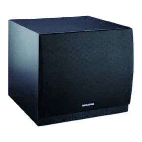
Dungeness Subwoofer
B A
www.blumensteinaudio.com

-2-
ank you for your purchase
Every cabinet from Blumenstein Audio is made by hand in our Seattle wood shop and all electronics are
thoroughly tested. As with most handmade pieces, every item we make is unique and there will be slight
variations in the wood grain, color, and cabinetry. We apply our high standards of quality to everything we
make and ship.
Getting Started
The Dungeness subwoofer is a compact powered subwoofer with a 25-watt integrated amplifier designed to
be used ideally with Orca Fullrange speakers. It is designed for maximum flexibility in regards to placement
options. Included in your purchase of the subwoofer are 2 lengths of thin gauge speaker wire to help you
get this new addition to your sound system up and running quickly and easily. When used properly, your
subwoofer will give you years of enjoyment.
Placement
Use common sense when placing your Dungeness subwoofer. Place it on a rm, level surface. If it is on a shelf
or cabinet, ensure that the xture can support the weight of the subwoofer and that there is adequate ventila-
tion around the subwoofer’s amplier. Avoid placing the Dungeness where it may be exposed to excessive heat.
Long-term exposure to sunlight can aect the cabinet’s nish.
For best performance, a single Dungeness should be placed between your Orca speakers. A pair of subwoofers
should be placed as close to each speaker as possible: underneath or side by side. If you need to place the sub-
woofer on the oor, separated from your speakers, be sure to keep it slightly behind or in line with the speakers
and not in front of them in order for your system to sound its best. It’s recommended that you isolate your
speaker cabinets from your source components, be it digital or analog.
Important Safety Instructions
All the safety and operating instructions should be read before this product is operated. e safety and operating
instructions should be retained for future reference.
To reduce the risk of electric shock, do not apply power while the amplier is disconnected from the subwoofer
enclosure. No user servicable parts are inside. e unit should be connected to an earth grounded AC electrical
socket. Do not defeat safety purpose of the polarized or grounding plug. If the provided plug does not t into
your outlet, consult an electrician for replacement of the obsolete outlet. Refer servicing to qualied personnel.
To reduce the risk of re and shock do not expose amplier unit to rain or moisture. Clean only with dry cloth.
Unplug the unit during lightning storms or when unused for long periods of time.
e unit should be operated in a well ventilated area. Minimum clearance is 2 inches from the ventilation open-
ings. Do not install near any heat sources such as radiators, heat registers, stoves, or other apparatus (including
ampliers) that produce heat. Protect the power cord from being walked on or pinched, particularly at the plugs,
convenience receptacles, and at the point where they exit the unit.
Note: Amplier unit is set at the factory for 115V operation. Unit may not be adjusted for 230V operation.

-2-
Back Panel and Connections
Input/Output Connections
1.) Low-Level Inputs (Le/Right)
RCA style jacks that will accept standard line level inputs from a pre-amp level source. ey will accept a stereo
signal and internally combine it into mono. (Note: Both le and right input jacks must be connected to the source
in order to drive the amplifer to full output).
2.) High-Level Inputs
Speaker level inputs using spring clip type jacks to permit connection with bare wire. Allows the user to connect
the speaker level output of a full range amplier to the input of the subwoofer amp using standard speaker wire. A
mono signal is derived from the stereo input, which then feeds the subwoofer amplier crossover input.

-3-
3.)High-Level Outputs
Speaker level passthrough outputs using spring clip type jacks to permit connection with bare wire. Used to
connect from the subwoofer amp to pass signal from the full range amp on the main L/R speakers. Signal is
only present on this output if the high level input is also used. e signal to the L/R speakers is not ltered. e
impedance “seen” by the fullrange source amplier will be that of the connected speakers only.
4.) Power Input
is unit features a hardwired AC power cable and externally-accessible fuse. It is supplied with an 0.75 A, 250V
fuse and USA-type polarized 2-pin plug. is unit is not suitable for 230V applications unless used with a voltage
inverter.
Controls/Indicators
5.)Power/Gain Knob (“Gain”)
is control will match the amplier’s input sensitivity to the output of the pre-amp source. If the source output has
a variable control, we recommend that the user spend a moment or two determining the best balance between the
controls. When a balance is found between low noise, linear level control, and sucient level to drive the amp to
the required output, the gain knob can be considered to be the “volume control” for the subwoofer system. To shut
the subwoofer amplier o, turn the control all the way to the le until it ‘clicks’. Alternatively, plug the amplier
into a power strip with an on/o switch and turn the subwoofer o via the power strip’s switch so as to keep the
gain knob in place. We recommend setting this knob to 10 o’ clock.
6.) Freqency Knob (“Freq”)
is control is used to establish the highest frequency that the subwoofer will reproduce and has a range between
60 to 180 Hz with a slop of 24 dB per octave. We recommend setting this knob to 10 o’ clock. Experiment with the
amount of “overlap” that you will experience when all speakers are playing in the same range. is can be helpful
when integrating the subwoofer with the rest of the system and with the room. Note: When using the amp with a
LFE (Low Frequency Eects) output on a pre-amp or home theater receiver the internal low pass lter circuitry
should be bypassed by turning the frequency control to maximum (180Hz). e home theater receiver should be
used to control the low pass crossover frequency.
7.) Power LED
When the power switch is moved to the “on” position, the LED will illuminate green, and the amp will be in “On”
mode. If the LED is not illuminated, check that the amplier is plugged into a power source and that the “Gain”
knob is not set to the “O ” position.

-4-
Connecting Source Components to Your Dungeness Subwoofer
Connecting via Speaker Level
I. Biwiring via Speakers
1. Untwist the binding post caps on your speakers.
2. Insert the included thin gauge bare wire and twist the caps back down.
3. On the back of your subwoofer, clip in the other ends of the bare wire
into the L and R ‘From Amplier’ connectors in the High Level Input.
4. Connect your speakers to your stereo amplier using banana plug
terminated cables.

-5-
II. Biwiring via Stereo Amplier/Receiver
Similar to the above method, only using your stere amplier or receiver as the biwiring point rather than the
speakers.
Note: Either I or II sounds the same; choose which biwiring method you prefer based on
convenience.
Recommended Settings
Gain knob: 10 o’ clock
Frequency knob: 10 o’ clock

-6-
Notes about Hum
While this amplier has been designed to minimize the possibility of hum, it is still possible that a hum will occur
in rare circumstancs. Its safety grounding can create a path for small amounts of 60 Hz energy to travel through the
line-level audio system. While not dangerous, this energy can interfere with the quiet enjoyment of your system.
e rst course of action should be trying to make sure that all of the audio components are connected to either
the same electrical outlet, or at least into the same circuit branch. Next, cable TV systems are notoriously the cul-
prit, so be sure to try disconnecting all coaxial feeds that are connected to the system. If this solves the problem,
install a coaxial line isolator and reconnect the system. In the very worst case, a line-level audio isolator/transform-
er connected to the line-in of the subwoofer amplier will usually solve the problem.
Warranty
is product is warranted for the period of one year. is warranty is limited to manufacturer defects, either in
materials or workmanship. In the rare case of a product failure, please contact Blumenstein Audio.
e warranty will not cover incidental or consequential damage due to defective or improper use of products. is
includes but is not limited to overheating, bent frames, and broken componentry.
Non-Warranty Service: If non-warranty service is required, the product may be sent to Blumenstein Audio for
repair/replacement, transportation fees prepaid, by contacting Blumenstein Audio directly for details, complete
instructions, and service charges.
Technical Specication
Rated Power Output 15 watts RMS into 8 ohms @ 0.1% THD
Signal to Noise Ratio 90 dB A-weighted
Input Impedance 10.4K ohms
Low Pass Adjustment 60 Hz -180 Hz
Power Requirements 120 VAC, 60 Hz, 48W
Physical
Dimensions 11-1/4” H x 11-1/4” W x 8 1/2” D
Material Birch ply, Chocolate Bamboo, or Natural Bamboo
Weight Birch: approx. 17; Bamboo: approx. 18
Table of contents
Popular Subwoofer manuals by other brands

Velodyne
Velodyne VMS-8 user manual
DB Drive
DB Drive Okur K5 10D4v2 Installation instructions & owner's manual
InCarTec
InCarTec SUB-US10 user manual

Boss Audio Systems
Boss Audio Systems Phantom D10F user manual

Nady Audio
Nady Audio ProPower PSW152 Features, instructions & technical data

Crunch
Crunch Ground Pounder GP10D2 Owners and installation manual
