manuals.online logo
Brands
  1. Home
  2. •
  3. Brands
  4. •
  5. Kicker
  6. •
  7. Subwoofer
  8. •
  9. Kicker SSUTAYU15 User manual

Kicker SSUTAYU15 User manual

Other Kicker Subwoofer manuals

Kicker KMW10 User manual

Kicker

Kicker KMW10 User manual

Kicker CompVR CVR10 User manual

Kicker

Kicker CompVR CVR10 User manual

Kicker CompVT CVT12 User manual

Kicker

Kicker CompVT CVT12 User manual

Kicker VSS PWRA4P15 User manual

Kicker

Kicker VSS PWRA4P15 User manual

Kicker CVX COMPVX10 User manual

Kicker

Kicker CVX COMPVX10 User manual

Kicker CompVR C18d User manual

Kicker

Kicker CompVR C18d User manual

Kicker SOLO-BARIC DS12L3 User manual

Kicker

Kicker SOLO-BARIC DS12L3 User manual

Kicker PTRTP10 User manual

Kicker

Kicker PTRTP10 User manual

Kicker S18XSP User manual

Kicker

Kicker S18XSP User manual

Kicker L7T8 User manual

Kicker

Kicker L7T8 User manual

Kicker CompVR C15vr User manual

Kicker

Kicker CompVR C15vr User manual

Kicker VSS SSON12 User manual

Kicker

Kicker VSS SSON12 User manual

Kicker Solo-Baric L5 User manual

Kicker

Kicker Solo-Baric L5 User manual

Kicker CompVR C8vr User manual

Kicker

Kicker CompVR C8vr User manual

Kicker DES12 User manual

Kicker

Kicker DES12 User manual

Kicker COMPETITION C18c User manual

Kicker

Kicker COMPETITION C18c User manual

Kicker DL7S12 User manual

Kicker

Kicker DL7S12 User manual

Kicker KM12 User manual

Kicker

Kicker KM12 User manual

Kicker COMPVT65 User manual

Kicker

Kicker COMPVT65 User manual

Kicker Comp DC12 User manual

Kicker

Kicker Comp DC12 User manual

Kicker COMP12D4 User manual

Kicker

Kicker COMP12D4 User manual

Kicker SOLO-BARIC S15L7 User manual

Kicker

Kicker SOLO-BARIC S15L7 User manual

Kicker S12L5 User manual

Kicker

Kicker S12L5 User manual

Kicker PSON13 User manual

Kicker

Kicker PSON13 User manual

Popular Subwoofer manuals by other brands

Extron electronics SF 8CT SUB user guide

Extron electronics

Extron electronics SF 8CT SUB user guide

SVS PB-4000 quick start guide

SVS

SVS PB-4000 quick start guide

Pioneer S-DVR9SW Service manual

Pioneer

Pioneer S-DVR9SW Service manual

Yamaha YST-SW515 Service manual

Yamaha

Yamaha YST-SW515 Service manual

Velodyne SPL-800 ULTRA - REV B datasheet

Velodyne

Velodyne SPL-800 ULTRA - REV B datasheet

Teufel US 2110/1 SW operating instructions

Teufel

Teufel US 2110/1 SW operating instructions

Wet Sounds SS-65 user manual

Wet Sounds

Wet Sounds SS-65 user manual

Pyle PLQB10 Specifications

Pyle

Pyle PLQB10 Specifications

Sony XS-L1536 Product guide

Sony

Sony XS-L1536 Product guide

Sony XS-AW8 operating instructions

Sony

Sony XS-AW8 operating instructions

B&C Speakers 15 HPL 76W Specifications

B&C Speakers

B&C Speakers 15 HPL 76W Specifications

Velodyne DD-18+ Specifications

Velodyne

Velodyne DD-18+ Specifications

Sonance Cinema Series SUB 10-150 Specifications

Sonance

Sonance Cinema Series SUB 10-150 Specifications

Hifonics HW-12 Owners & installation manual

Hifonics

Hifonics HW-12 Owners & installation manual

Yamaha 64263 owner's manual

Yamaha

Yamaha 64263 owner's manual

Magnat Audio ADR 130 BP user manual

Magnat Audio

Magnat Audio ADR 130 BP user manual

Technics SB-AS500 Operaing instructions

Technics

Technics SB-AS500 Operaing instructions

Lyngdorf BW-2 owner's manual

Lyngdorf

Lyngdorf BW-2 owner's manual

manuals.online logo
manuals.online logoBrands
  • About & Mission
  • Contact us
  • Privacy Policy
  • Terms and Conditions

Copyright 2025 Manuals.Online. All Rights Reserved.

1
SSUTAYU15
Designed for 2015 and newer Chevrolet® Tahoe/Suburban and GMC® Yukon/Yukon XL vehicles
©2018 Stillwater Designs
SSUTAYU15 - 20180313
Subwoofer Assembly
Subwoofer Harness
Subwoofer Power Harness
Wire Ties X 6
Fuse
Foam Pad
Bolts X 2
Nut
Plastic Fastener
Adapter Harness
Module Relocation Bracket (rear)
Lower Bracket (long)
Lower Bracket (short)
2
Disassembly
Disconnect the negative battery cable from the battery.
Note: On vehicles equipped with dual batteries, disconnect negative battery cable
from both batteries.
Using a panel removal tool, pry loose the driver’s side front and rear threshold panel along the bottom of
the dooropenings. Fig. 1 & 2
Open the storage compartment lid and locate the two knobs
underneath the rubber liner that secure the storage compartment
to the vehicle. Unscrew the knobs and lift the storage
compartment out of the vehicle. Fig 3
Using a panel removal tool, pry loose the upper and lower cargo
door sill plate. Fig 4 & 5
Fig 5
Fig 4
Fig 2
Fig 1
Fig 3
3
Using a panel removal tool pry loose the screw cover on the driver’s side C and D pillar post cover and
remove the screws securing both covers. Pry loose the C pillar post cover and lay aside. Pry loose the D
pillar post cover, disconnect speaker wiring and lay aside. Fig 6
Using a pick tool, snap loose the cover on the driver’s side cargo D-ring to reveal the bolt securing the D-
ring and remove the bolt. Fig 7
Unscrew the cargo-net anchor knob on the driver’s side. Fig 8
Note: The knob may unscrew from the threaded stud. If so, use a pair of pliers to
remove the stud being careful not to damage the threads. Replace plastic knob
onto the stud for reassembly later.
Slide the driver’s side second row seatbelt trim cover up to reveal the seatbelt bolt and remove the bolt.
(Tahoe/Yukon only) Fig. 9 Torque to 45Nm.
Using a panel removal tool, pry loose the driver’s side quarter panel cover. Disconnect the rear 12 volt
accessory port wiring and the rear folding seat switch wiring (if equipped) and lay the quarter panel cover
aside in the cargo area.
Fig 6
Fig 7
Fig 8
Fig 9
4
Wire Routing
Remove the red battery terminal cover and thenthe power distribution cover next to the battery on the
passenger’s side.
Remove the fuse from the fuse holder on the subwoofer power harness. Connect the ring terminal of the
subwoofer harness to the power lug identified in Fig 10. Torque to 9 +/- 1.5Nm.
Route the power wire along the fire wall to the factory grommet on the driver’s side and secure withwire
ties.
Using a razor knife, make a cross shaped incision in the protrusion large rubber grommet and feed the
power wire straight through the hole on the cabin side of the grommet. Fig11
Install the black two pin power connector on the subwoofer power harness by first inserting the terminal
fully into the connector and then depressing the blue retainer. Fig 12
Note: Make sure the blue retainer in the center of the connector is not depressed – it
should be flush with the front of the connector. If the retainer is depressed, the
terminal will not fully seat in the connector body. Make sure the terminal is
installed into position 1 on the connector body. There should be a block-out
plug installed in position 2 in order to prevent the terminal from being installed
into the wrong position on the connector.
Connect the subwoofer power harness two-pin connector to the subwoofer harness two-pinconnector.
Connect the black ground wire of the subwoofer harness to the bolt next to the parking brake pedal
indicated in Fig 13 Torque to 9 +/- 1.5 Nm.
Connect power
wire to this lug
Fig 10
Fig 11
Insert
terminal
first
Then
depress
blue
retainer
Fig 12
Connect ground
wire to this bolt
Fig 13
5
If the vehicle is equipped with a base audio system, (non-Bose®)
find the brown with blue stripe wire and the blue wire that are
twisted together in the factory harness near the parking brake
pedal. Install the supplied wiretaps onto the vehicle wires.
Connect the green wire if the adaptor harness to the blue wire of
the vehicle harness and the brown wire of the adaptor harness to
the brown/blue stripe wire of the vehicle harness. Fig. 14
Note: If vehicle is equipped with premium audio (Bose®) refer
to input connection indicated later in this manual.
Note: There are input connection points on both ends of the subwoofer harness. Only one of the
two connection points will be used depending on whether the vehicle is equipped with premium or
base audio.
Connect the white two-pin connector of the adaptor harness to white two-pin connector of the subwoofer
harness.
Continue routing the subwoofer harness down the driver’s side of the vehicle to the rear quarter panel.
Open the cover of the wire tray along the threshold of the door, install wire and replace the tray cover.
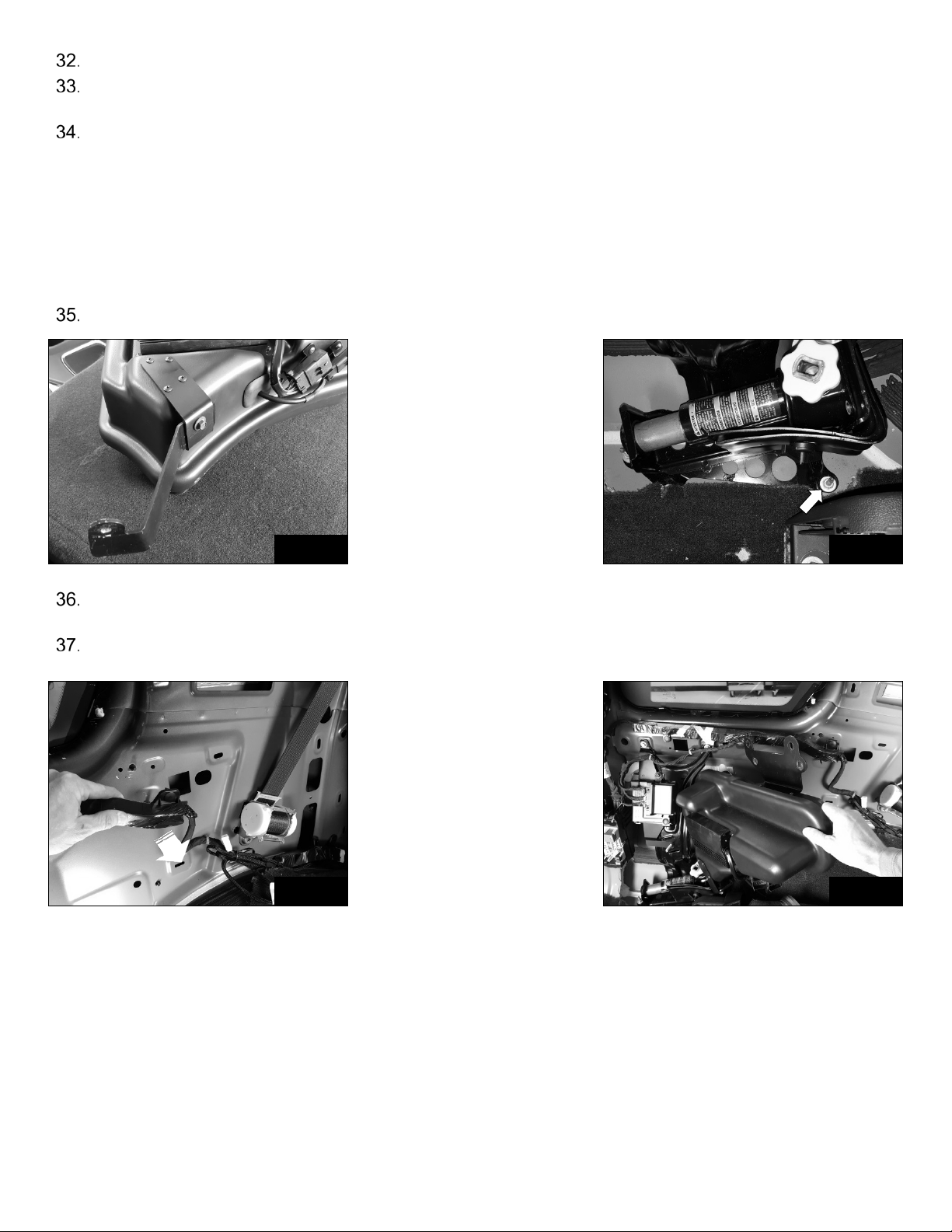
Subwoofer Installation
Locate the factory module bracket and remove the two nuts securing it. Fig 15
Pry the module wire retainers from the factory bracket. Fig 15
Note: Depending on the vehicle trim level, there may be one or two modules attached
to the bracket. The module(s) will need to be relocated using the supplied
relocation bracket in order for the subwoofer to be installed.
Note: Do not disconnect the module wiring. Modules wiring is shown disconnected
in some pictures only for clarity of installation.
Pry out the center portion of the plastic retainer securing the smaller module and then the outer portion.
Remove the module from the factory bracket. Fig 16
Fig 15
Fig 16
Fig 14
6
If equipped, remove the larger module by snapping it out of the factory bracket.
Pull the factory module bracket from the metal and discard.
If equipped with two modules, slide the larger module into the relocation bracket first as shown in Fig 17
Using the supplied bolt and plastic fastener, install the smaller module over the top of the larger module as
shown in Fig 18
Note: The connectors on the smaller module face the opposite direction as the
connectors on the larger module. The smaller module mounts the same way
regardless of whether or not there is a second module.
Unscrew the jack tool-bag knob and remove the tool-bag. Fig 19
Remove the bolt indicated in Fig 19
Install the module relocation bracket as shown in Fig 20 and reinstall bolt.
If the vehicle is equipped with factory premium audio (Bose®),
locate the amplifier behind the jack mounting bracket. Disconnect
the connector indicated in Fig 21
Find the gray/black and blue/gray wire in the connector and install
the supplied wiretaps onto the wires. Connect the green wire of
the supplied adaptor harness to the blue/gray wire and the brown
wire of the adaptor harness to the gray/black wire.
Fig 17
Fig 18
Fig 19
Fig 21
Fig 20
7
Reconnect the amplifier connector to the amplifier.
Connect the white two-pin connector of the adaptor harness to the white two-pin connector of the
subwoofer harness.
There are two lower subwoofer brackets provided depending on the wheelbase of the vehicle. For
Tahoe/Yukon use the longer bracket. For Suburban/Yukon XL use the shorter bracket. Determine the
lower subwoofer bracket needed and attach it to the subwoofer using the supplied nut and bolt as shown
in Fig 22
Note: The lower subwoofer bracket should overlap the bracket attached to the
subwoofer as shown. The nut should be installed on the side closest to the
subwoofer. Leave the nut and bolt slightly loose so the lower bracket can
slide.
Remove the nut that secures the jack bracket indicated in Fig 23
Pull the factory wire harness slightly away from the metal in order for the subwoofer upper bracket to pass
under the factory wire harness. Fig 24
Hold the subwoofer at about a 45 degree angle and slide the lower subwoofer bracket over the jack stud.
Fig 25
Fig 22
Fig 25
Fig 23
Fig 24
8
Swing the subwoofer into position and over the studs where the factory module bracket attached. Install
the nuts and tighten. Fig 26
Note: The lower set of holes in the upper bracket are for Tahoe/Yukon and the upper
set of holes are for Suburban/Yukon XL
Reattach the factory wire harness to the metal.
Install the nut on the jack stud and tighten.
Tighten the nut and bolt attaching the subwoofer lower bracket to the subwoofer.
Connect the ten-pin and four-pin subwoofer connectors to the subwoofer.
Install the jack tool-bag as shown in Fig 27.
Note: The tool-bag will be positioned more aft of its original position but will not
interfere with reassembly of quarter panel cover.
Reinstall panels in reverse order.
Install fuse in fuse holder.
Reconnect negative battery cable(s). Torque to 17Nm
Disable Active Noise Cancellation (ANC) – refer to programming procedure (1).
Note: Not necessary for all vehicles. See attached service bulletin for more
information.
Fig 26
Fig 27
9
Addendum
•Vehicles affected: All 2014 - up Chevrolet Silverado/GMC Sierra 1500/2500/3500
trucks equipped with ANC (Active Noise Cancellation)
•Note: In order for the subwoofer to operate correctly, Active Noise
Cancellation (only available on trucks equipped with 6.2L engine) must be
disabled. Due to the increased output of the Kicker® subwoofer, failure to
disable ANC will result in a “feedback” issue between ANC and the subwoofer
at certain RPM’s. Disabling ANC is easy and can be reversed if the Kicker®
subwoofer is ever removed from the vehicle.
•ANC can be disabled in one of two ways.
1) Follow the following steps in the Disabling Active Noise cancellation
section.
2) Visit a GM dealership and have the Active Noise Cancellation disable
through the Audio Control Module*.
*Will require additional fee.
10
Disabling Active Noise Cancellation (ANC)
1. Using a panel tool, remove the screw cover from the driver’s side visor. Fig. 1
2. Remove the three screws securing the visor, pull visor loose and disconnect wiring.
3. Open the screw covers on the grab handle above the driver’s door, remove the two screws and pull loose
handle. Fig. 2
4. Snap loose the driver’s side A pillar cover slightly. Cover doesn’t need to be completely removed. Fig. 3
5. Pull down the rubber door seal along the top of the driver’s door. Fig. 4
6. Pull down slightly on the headliner to expose the black adhesive tape covering the microphone.
7. Carefully remove the black tape so that it can be re-applied. Fig. 5
8. Find and disconnect the microphone wiring. Disconnecting just one of three microphones will disable the ANC.
Fig. 6
9. Re-apply the black adhesive tape over the microphone and connecters.
10. Re-install previously removed parts in reverse order.
Fig. 2
Fig. 1
Fig. 4
Fig. 3
Fig. 6
Fig. 5