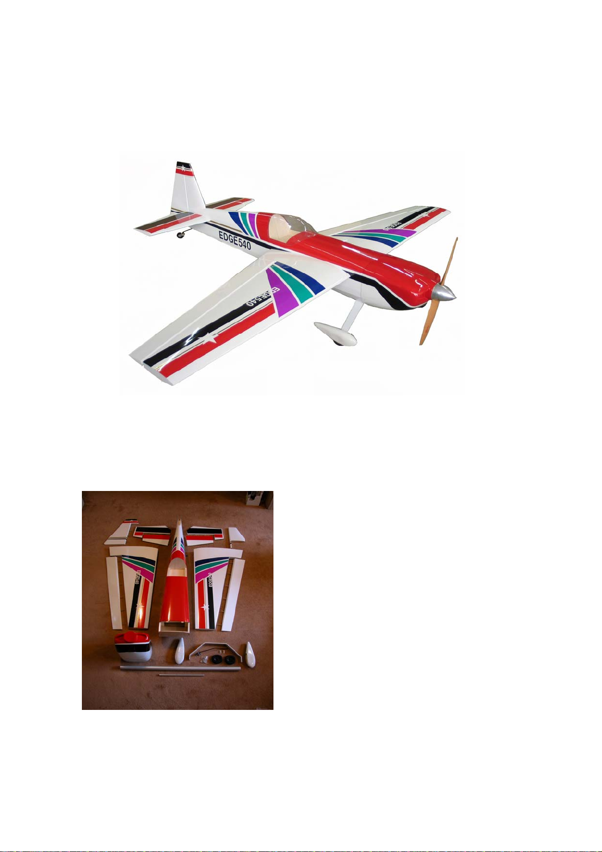
BME Aircraft Edge 540 User manual


Other BME Aircraft Toy manuals


Popular Toy manuals by other brands


V-tech
V-tech Rattle & Sing Puppy user manual

V-tech
V-tech Safari Sounds Parents' guide

De Agostini
De Agostini Model Space H.M.S. Bounty Admiralty Assembly instructions

V-tech
V-tech Go Go Smart Wheels Race Car II user manual

V-tech
V-tech Disney Go! Go! Smart Wheels Mickey Mouse Gas & Go Repair... Parents' guide

PLAYTIVE JUNIOR
PLAYTIVE JUNIOR MY FIRST TOOTH Instructions for use

Stevens Aero Model
Stevens Aero Model XS480 Product support

WATT AGE
WATT AGE WILD CAT 400 EP Instructions for final assembly

R/Evolution
R/Evolution Roguewave RVOS01002T1 instruction manual

KNEX
KNEX Lightning Flash Roller Coaster instructions

Cra-Z-Art
Cra-Z-Art MoonLight Monsters Starlight Stage instruction manual

Modeltech
Modeltech Mini Mach Racer Assembly instructions