BME Aircraft PAU Pitts User manual

BME Aircraft
27% Pitts Special Challenger
Congratulations and thank you for choosing BME Aircraft 27 % Pitts
Special Challenger. Before you start assembling, please pay attention to
this step by step instruction manual and follow the steps when
assembling.
I. Beforeassembling
1. Parts check list--
When you open your box of 27 %
Challenger, check all parts inside.
They should include as following:
1x fuselage 1x cowl
2 sets of main wings with ailerons
1 set of stabilizer and 2 elevators
1 set of fin and rudder
2x wing joiners 1x fuse belly
1x upper wing centre joiner
1
1 pair of wing strut 1x canopy
1 pair of main wheel / wheel pants 1x hardware pack
1 set of tail wheel assembly 1 set of nylon sticker (3x ORACLE
1x landing gear and block 2x BME Aircraft)
1 set (4x) center cabane
2. Iron all film cover area---
Before you start assembling, Iron all film covered area to make sure
that the film stick on firmly.
3. Cut out film covered area
Cut out the film that covers the opening like servo mount, hinges etc.
II. Start assembling
A. Fuselage—
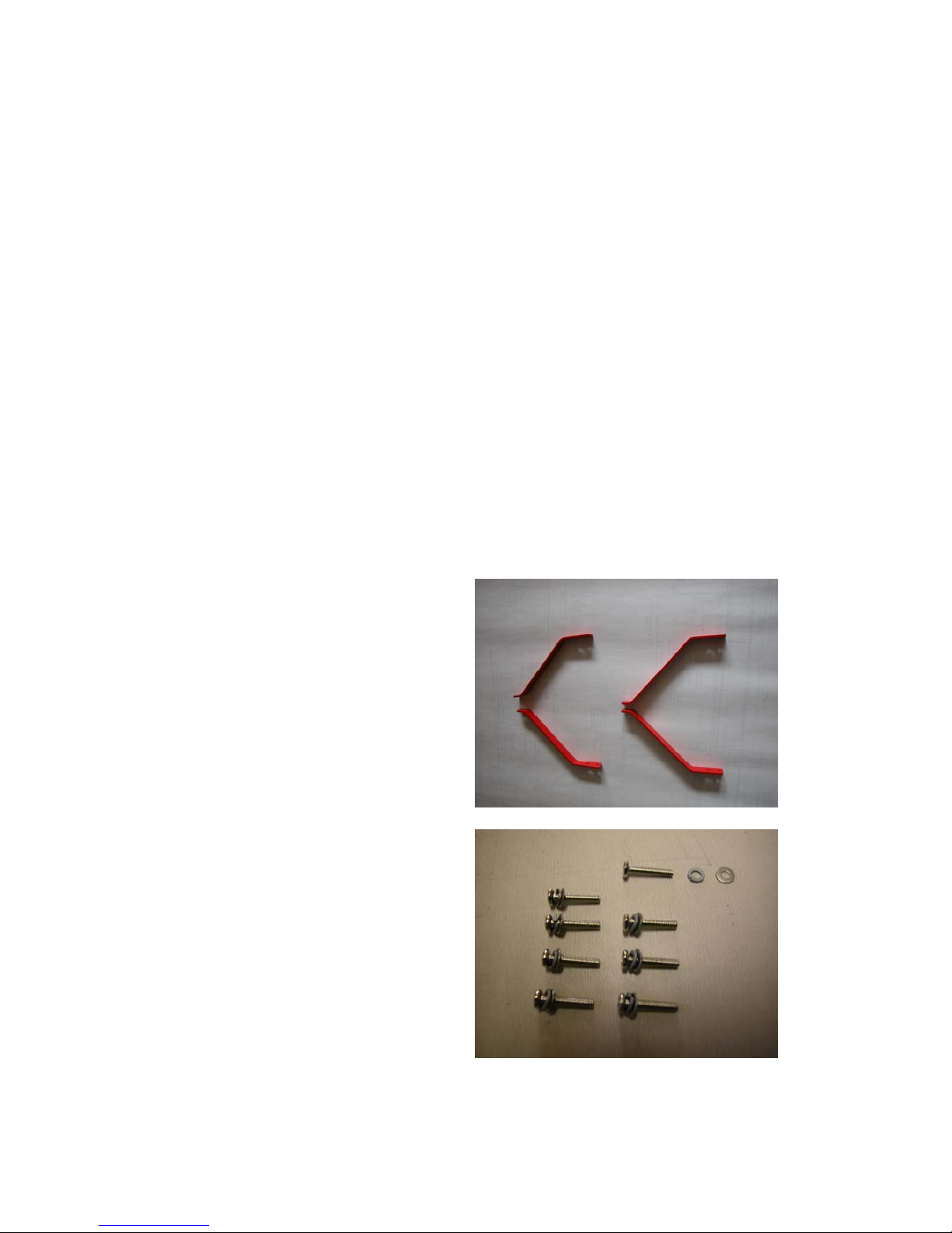
1. Center cabane
a.Find 4 pcs of aluminum
center cabane from the bags.
There should be two longer
ones and two shorter ones.
Then find the pre-cut 4 slots on
top of the fuse front. Insert 4
cabanes into 4 slots. The
shorter ones goes into the front
slot, longer ones into the rear.
Find 1/2” 4-40 screws from the
hardware pack with the washers
and spring washers to secure
the cabane in place. Thread
lock is required on these
screws.
b. Use two Y-harness, one on
each side of the rear cabane for
aileron connection.
2
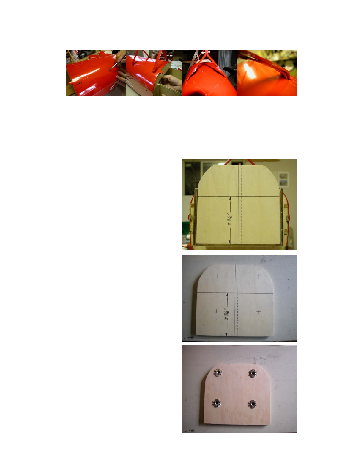
2. Fire wall installation—
a.The fire wall in this ARF
come unglued for easy access to
install cabane. After the cabane
installation, it’s time to install fire
wall. First try fitting the fire wall
into the engine box. Trim the fire
wall if necessary.
Draw a line 3 3/16” away the fire
wall bottom and the vertical
center line.
To achieve a 3 degree thrust angle,
you must calculate the offset
distance according to the length
from the hub to the mounting plate.
For a 50 cc engine the offset
usually around 0.5 cm. Draw a dot
line as the offset line.
The intersection of two line is your
engine shaft center point.
b.Mark the location of the
mounting screw holes, drill and
insert the T-nuts in place.
c. Glue the fire wall with 30 min.
epoxy. Then glue the included
3

balsa tri-block on the corner of the fire wall and box side wall. Install the
gas tank before the fire wall is glued on.
d. Drill and install dowels from the box side wall into the fire wall.
e. The length from fire wall to
the front surface of prop hub
should be 5 3/4”. Install hard wood
block between fire wall and engine
mounting plate if necessary.
3. Landing gear---
a.Screw the wheel axles onto
the landing gear. Then install
wheel using collars to secure
wheel on the far end of the axle.
b. Mark and drill holes for axle
and screws according to the
pre-drilled holes on the landing
gear.
c. Install 4-40 T-nuts to the
inside of the wheel pants for wheel
pant holding screws.
d.Cut a axle access as the photo
shown above.
e. Put both wheel pants on and
secure them with 4-40 screws
remember to use washers and
spring washers.
4
f. Install landing gear onto the mounting plate using the provided
screws.
g. Cover landing gear with the balsa block. And secure the block with
provided screws..
5
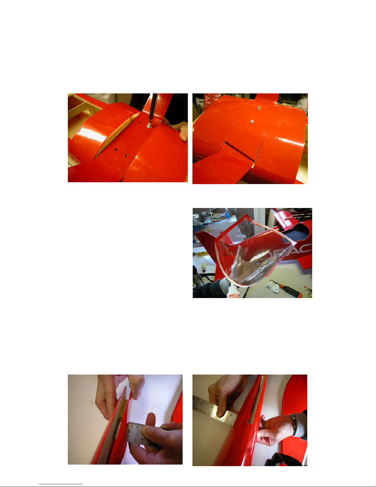
4. Canopy—
a.Try fitting the canopy in place.
Draw a line along the edge of
the canopy.
b. Drill three small holes (same
size as the screws you’d use)
on each side of the canopy.
c. Apply plastic glue along the
inside of canopy frame, then
put back to where it should be
and screw it on.
5. Stabilizer and Vertical fin—(finish the wing assembling before you
proceed this step)
a.Measure and draw a center line of the stab on both side.
b. Take the measurement of the front and rear of opening for stab.
Other BME Aircraft Toy manuals


Popular Toy manuals by other brands

FUTABA
FUTABA GY470 instruction manual

LEGO
LEGO 41116 manual

Fisher-Price
Fisher-Price ColorMe Flowerz Bouquet Maker P9692 instruction sheet

Little Tikes
Little Tikes LITTLE HANDIWORKER 0920 Assembly instructions

Eduard
Eduard EF-2000 Two-seater exterior Assembly instructions

USA Trains
USA Trains EXTENDED VISION CABOOSE instructions


