BMI IDP1010 User manual
Read safety and operating instructions carefully before operating the
saw for the fi rst time. Retain manual for future reference.
ATTENTION!
Owner’s Manual
Keep for your records
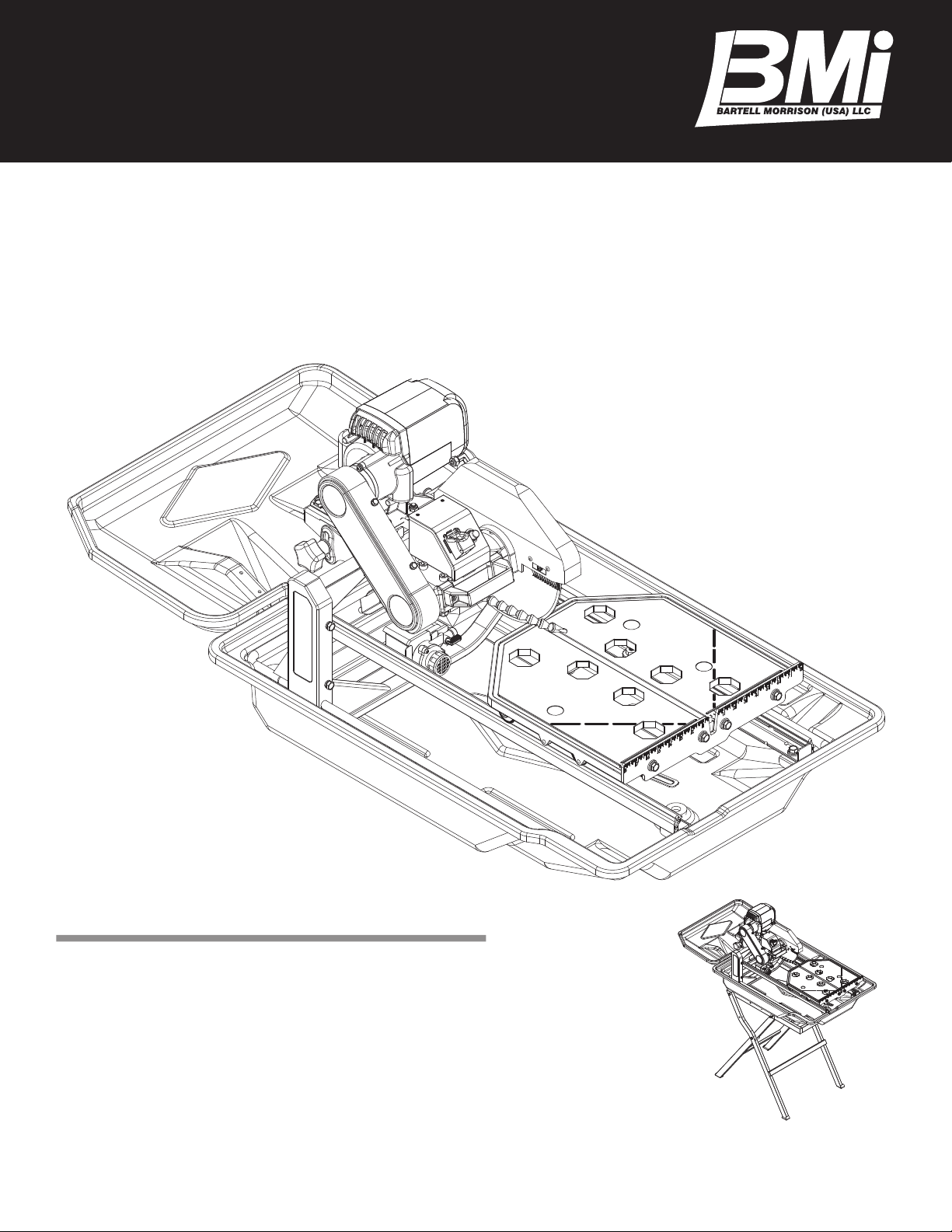
Optional
Saw Stand
IDP1010
Wet Tile Saw


Contents
Contents 2
Safety Precautions 3
Health Warning 4
Unpacking 4
Set Up 4
Features 5
Specifications 5
Installation and Operation 6
Saw Stand Setup 6
Blade Installation 6
Water Pump Installation 6
Using the Cutting Table 7
Using the Rip Guide 7
Performing Diagonal Cuts 7
Performing Miter Cuts 7
Setting the Cutting Depth 7
Cleaning the Water Tray 7
Transporting the Saw 8
Proper Blade Use 9
Care And Maintenance 10
General Rules 10
Cleaning 10
Prolonged Period of Nonuse 10
Extreme Temperature 11
Water Pump Maintenance 11
Belt Replacement 11
Realignment 12
Leveling Adjustment 14
Electrical Specifications 15
Recommendations 15
Electrical Wiring Diagram 15
Extension Cord Chart 15
Troubleshooting 16
Replacement Parts List 19
Accessories 24
How to Order 25
Customer Service 25
Contact Us 26
Warranty 27

IDP1010 • Owner’s Manual
3
Safety Precautions
A. Saw blade should be inspected daily for excessive wear,
core cracks and arbor damage. Replace any blade that
shows signs of damage.
B. To mount the blade, clean the arbor and outer flanges,
and tighten the nut securely.
C. DO NOT place any portion of your body in line with the
blade while it is rotating.
D. Wet cutting blades MUST be used with water.
E. To reduce the risk of electrical shock, we recommend
the use of GFCI and to refer servicing to a qualified pro-
fessional.
F. When operating the saw, be sure to wear proper safety
gear, such as safety glasses, dust mask, and hearing
protection. A hard hat is also recommended.
G. Never use the machine improperly or work in an unsafe
manner.
H. Maintain alertness while operating the machine. Failure
to maintain attention, by the operator, may lead to seri-
ous injury.
I. Keep work area clean.
J. Before you start working, familiarize yourself with the
work site and its surroundings. Take notice of circum-
stances which may impede work or traffic, observe soil
conditions (good bearing or not) and take measures to
ensure safety (e.g. the shielding of roadworks from pub-
lic traffic).
K. Take measures to ensure that the machine is in a safe
and trouble-free condition prior to usage. Use the ma-
chine only when all protective devices (i.e. guards, noise
absorbers, emergency-off devices) are in place and in
working order.
L. A visual check of the machine must be made at least
once a shift to ensure that visible damages or faults
are recognized. Any changes (including changes in
the performance or behavior of the machine) must be
reported to the supervisor. If necessary, stop the ma-
chine at once and secure it.
M. In the case of a malfunction, stop the machine imme-
diately and secure it. Fix the problem as soon as pos-
sible.
N. To stop and start the machine follow the operating in-
structions and observe any indicator lights.
O. Keep out of reach of children. Before operating ma-
chine, be sure the activated machine will be of no dan-
ger to anyone.
P. Be sure to connect the plug to a properly grounded re-
ceptacle to reduce the risk of electric shock.
Q. Wear proper apparel. Do not wear loose clothing or ac-
cessories. Keep hair and body parts away from open-
ings and moving parts.
R. If cord/plug is damaged do not operate.
S. Make sure power switch is in “off” position before plug-
ging in power cord to prevent any accidental activation.
T. When machine is plugged in do not leave it unattended.
Unplug prior to servicing, when changing accessories,
and when not in use.
U. Never carry machine by cord. Do not pull cord to un-
plug. Keep cord away from heat, sharp edges and oil.
V. Do not operate the machine when you are tired or while
under the influence of drugs, alcohol or any medica-
tion.
W. Never operate this unit when flammable materials or va-
pors are present. Electrical devices produce sparks or
arcs which can cause a fire or explosion.
X. When using an extension cord, make sure it is in good
condition and heavy enough to carry the current drawn
by the machine. Refer to the extension cord table in the
“Electrical Specifications” section for the correct gauge
depending on the desired cord length and the machine’s
horse power and voltage.
WARNING

4
Health Warning
Some dust created by power sanding, sawing, grinding,
drilling, and other construction activities contain chemicals
known to cause cancer, birth defects or other reproductive
harm. Some examples of these chemicals are:
• Lead from lead-based paints,
• Crystalline silica from bricks, cement and other
masonry products, and
• Arsenic and chromium from chemically-treated
lumber.
Your risk from these exposures varies, depending on how
often you do this type of work. To reduce your exposure
to these chemicals: Work in a well ventilated area, and
work with approved safety equipment, such as those dust
masks that are specially designed to filter out microscopic
particles.
Unpacking
Open the container and carefully lift the saw by the foam packag-
ing and place it on a flat, level working area. Be sure that you
have the following items before you discard the container:
• Saw
• Plastic water tray
• Rear drip tray
• 10” saw blade
• Universal wrench
• Water pump
• Rip guide
• Owner’s manual
• Drain plug
See also page 23 for additional optional accessories.
Set Up
Proceed to the following section to complete the assembly
of the saw:
1. Slide water pump onto U-shaped bracket located at the
bottom of the frame. (see figure 1)
2. Slide cutting head onto the post. Secure cutting head
to the shaft using the provided flat washer, lock washer
and nut. Then attach cutting depth control knob and
washer to the cutting head through the slot located un-
derneath the belt guard.
3. Mount blade guard onto shaft protruding from the side
of the cutting head. Secure the blade guard in place
using the provided serrated washer and blade guard
knob.
4. Attach rear drip tray to the water tray.
figure 1
IDP1010 • Owner’s Manual
5
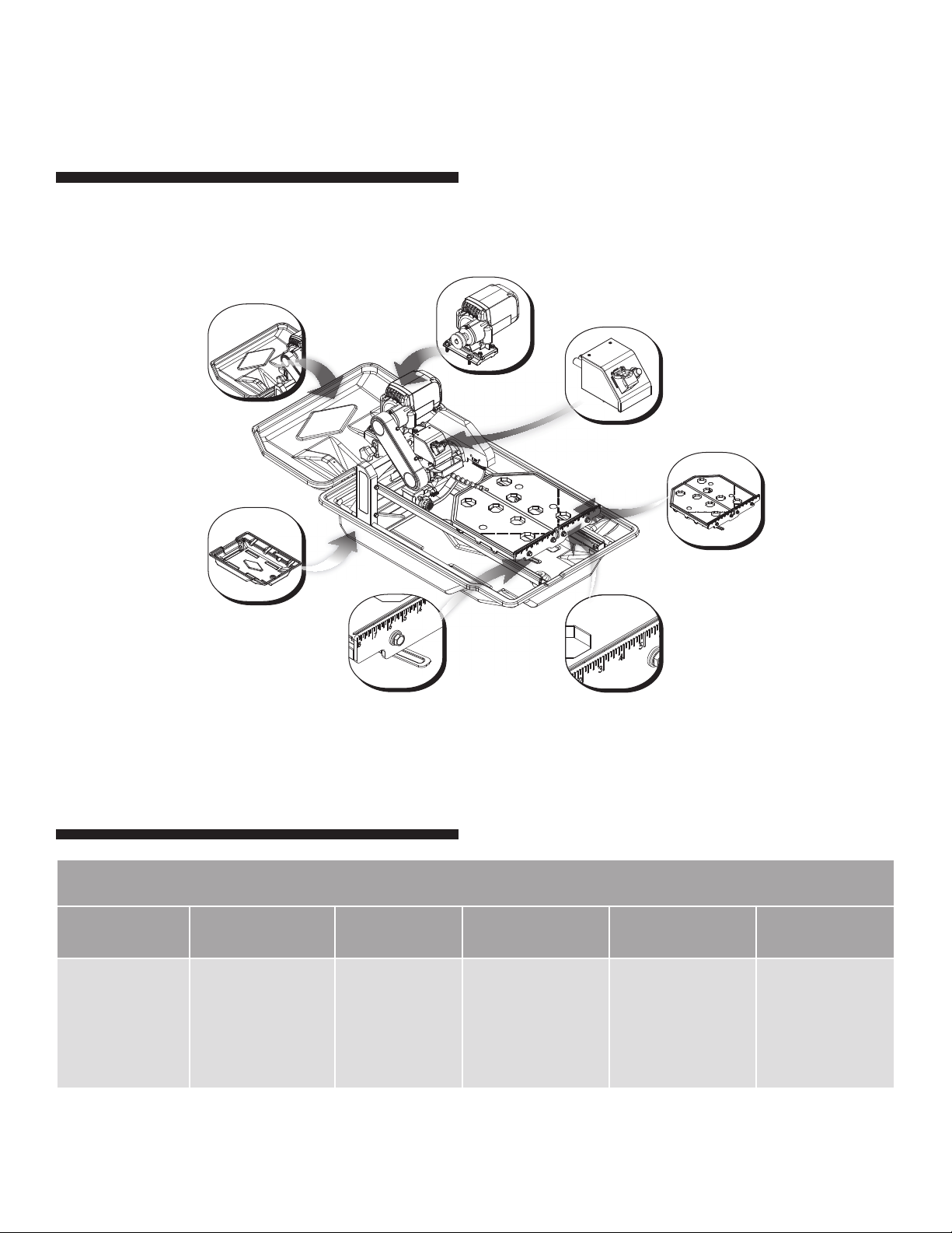
Carbon Brush Motor
Generates more torque and is physi-
cally smaller and lighter than similarly
rated induction motors.
Thermal Overload Protection
Prevents the motor from overheat-
ing and protects the saw from power
surges.
Cutting Table
Features an injection mold rubber
mat that provides a fi rm, durable
work surface while the ball bearing
wheels and rollers ensure smooth ef-
fortless movement.
Ruler Guide
The guide allows convenient mea-
surements and promotes precision
cuts.
Table Retention Device
The device secures the cutting table
when transporting the saw.
ABS Water Tray
ABS is a lightweight alternative to
stainless steel and offers excellent
durability.
Features
Specifi cations
Bartell Morrison IDP1010 TILE SAW
Motor Max. Blade
Capacity Cutting Length Cutting Depth Weight Dimensions
2 HP,
115 V/60 Hz,
3000 RPM
10” blade with 5⁄8”
arbor
24”,
Diagonally cut
16” tile
3½” 65 lbs
Length: 36.5”
Width: 26”
Height: 20.4”
Drip Tray
Rear drip tray increases the surface
area for collecting water and slurry to
prevent spillage.
* Dimensions do not include drip tray.
6
Installation and Operation
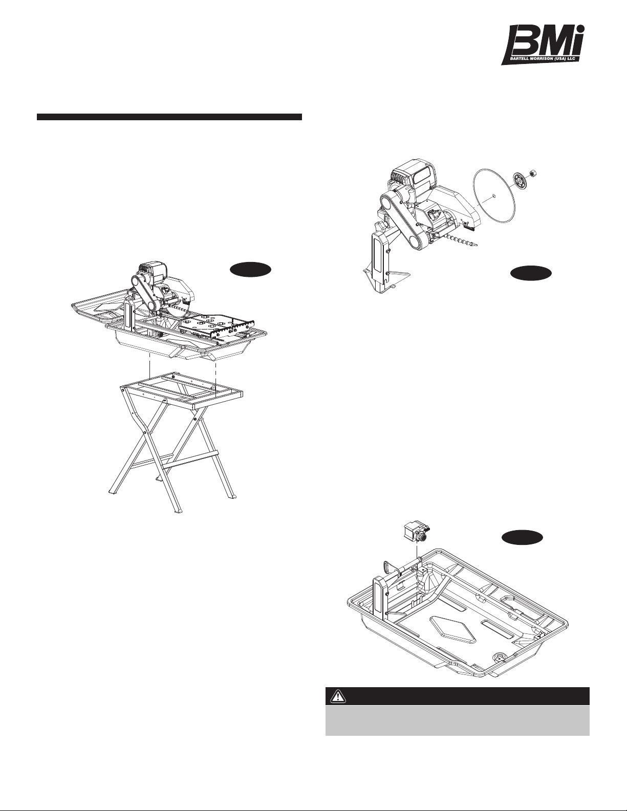
SAW STAND SETUP
1. Remove the folding stand from its box.
2. While holding the stand upright, spread both sets of legs
apart and swing the workbench over and on top of the
legs.
3. Seat the saw securely onto the stand. (see figure 2)
BLADE INSTALLATION
1. Loosen blade guard adjustment knob located at the rear
of the blade guard. Raise the blade guard to the highest
position and retighten the knob.
2. Remove the blade shaft nut and outer flange. (see fig-
ure 3) If a blade has been mounted, hold the blade with
one hand and use the other hand to loosen the nut with
the universal wrench. Remove existing blade.
3. Mount new blade, but make certain the arrow on the
blade coincides with the rotation direction of the shaft.
4. Attach outer flange and blade shaft nut. Hold the blade
with one hand and use the other hand to tighten the nut
with the universal wrench. Make certain the flanges are
pressed flush against the blade and that the nut is firmly
tightened, but do not over tighten.
5. Loosen blade guard adjustment knob, lower the blade
guard and retighten the knob.
WATER PUMP INSTALLATION
1. Remove the water pump from the box and check that it
is not damaged.
2. Slide the pump onto the U-shaped bracket located at
the bottom of the frame. The pump should be oriented
such that the water outlet is horizontal. (see figure 4)
3. Connect water hose from the bearing housing located
on the underside of the cutting head to the water pump.
Plug the pump’s power cord into the connector leading
from the switch box.
4. Fill the water tray so that the water intake is fully im-
mersed. Proper water level must be maintained at all
times during saw operation.
Disconnect the pump before attempting to handle the
pump. Never operate pump without water in the tray.
WARNING:
figure 3
figure 2
figure 4

IDP1010 • Owner’s Manual
7
USING THE CUTTING TABLE
• The ruler guide has inches marked along the top to al-
low convenient measurements and to promote preci-
sion cuts. (see figure 5)
• The table the table spans an area of 16” x 16”. With
the optional side extension table equipped, the cast alu-
minum cutting table spans an area of 25” x 16”, which
allows it to provide greater support for handling larger
materials.
• Cutting table is covered by a rubber mat that provides a
firm, durable work surface.
• A rip guide should be used together with the cutting ta-
ble to ensure precision while making cuts.
USING THE RIP GUIDE
1. Set the rip guide at the desired location on the ruler
guide and tighten the threaded knob. Make sure that
the rip guide is firmly tightened to avoid slippage. The
rip guide can be used for 45˚ and 90˚ cuts.
2. After the rip guide is positioned for the desired cut, place
material flat against the rip guide and the ruler guide.
3. Now you are ready to make your cut.
PERFORMING DIAGONAL CUTS
1. Remove threaded knob from the end of the rip guide
with the horizontal groove and insert it into the other end
with the diagonal groove.
2. Set the rip guide onto the ruler guide, such that the top
edge of the rip guide is aligned with the diagonal groove
to the left of the vertical channel in the cutting table.
Tighten threaded knob once in place.
3. Place one corner of the material being cut in the vertical
slot of the ruler guide and rest the adjoining edge flat
against the rip guide.
4. Now you are ready to make your cut.
PERFORMING MITER CUTS
To make miter cuts, an optional miter block must be pur-
chased.
1. Place the lip of the miter block on the ruler guide with the
threaded knob facing you.
2. Position the miter block such that a tile laying flat against
the block may rest its left-most edge within the vertical
channel of the cutting table. Tighten the threaded knob
to secure the miter block in place.
3. Place material onto miter block and you are ready to
cut.
SETTING THE CUTTING DEPTH
The recommended cutting depth is ¼” below the cutting
table surface. To adjust the cutting depth, loosen the cut-
ting depth control knob and set the cutting head such that
the lowest point of the blade is ¼” below the table surface.
CLEANING THE WATER TRAY
1. Remove the rear drip tray.
2. Lift the saw up from inside the water tray.
3. Remove the drain plug and drain any water left inside
the water tray.
4. Flush water into the tray while holding it upright to re-
move any sludge buildup.
Blade Diameter Cutting Depth
7” 1¾”
10” 3½”
figure 5
Setting the blade too low may damage the cutting table
and if set too high, the blade may grab the material being
cut, possibly causing injury to the operator and the saw.
WARNING:

8
5. Replace the saw back into the water tray.
6. Attach the rear drip tray. (see figure 6)
TRANSPORTING THE SAW
1. Ensure that the water tray is empty and dry.
2. Unplug the power cord and store it in the water tray.
3. Secure the cutting table to the front of the saw using the
table retention device.
4. Tighten the cutting depth control knob.
5. Optionally the rear drip tray may be removed and set in
the water tray for better handling.
figure 6

IDP1010 • Owner’s Manual
9
Proper Blade Use
Dos Don’ts
Wet Cut
Blades
• Inspect blades daily for cracks or uneven
wear.
• Always use appropriate blade for material be-
ing cut.
• Inspect arbor shaft for uneven wear before
mounting blade.
• Always use blades with the correct arbor
shaft size.
• Ensure that blade is mounted in the correct
direction.
• Use proper safety equipment when operating
the saw.
• Always have a continuous flow of water on
both sides of blade.
• Secure the blade to the arbor with a wrench.
• Do not operate the saw without safety guards
in position.
• Do not operate the saw with blades larger
than 10”.
• Do not cut dry with blades marked “Use
Wet”.
• Do not exceed manufacturer’s recommended
maximum RPM.
• Do not force blade into material. Let blade
cut at its own speed.
Dry Cut
Blades
• In addition to the following, always follow wet
recommendations.
• Use appropriate blade for material being cut.
• Inspect segment blades for segment cracking
or loss.
• Do not use damaged blades.
• Use proper safety equipment when operating
the saw.
• In addition to the following, always follow wet
recommendations.
• Do not make long cuts with dry blades. Allow
them to air cool.
• Do not use the edge or side of blade to cut or
grind.
• Do not attempt to cut a radius or curve.
• Do not cut too deep or too fast into the mate-
rial.
• Do not cut any material not recommended by
blade manufacturer.

10
Care and Maintenance
GENERAL RULES
• Always clean the machine before performing any main-
tenance/repair.
• Before performing any cleaning/maintenance/repair,
the machine must be switched off with the main power
switch.
Steps to Follow When Cleaning:
• Please do not use aggressive cleaners (i.e. containing
solvents). Do not use high-pressure water jets, aggres-
sive detergents or solutions and liquids with a tempera-
ture exceeding 86ºF! Use a fluff-free cloth only.
• Use a cloth which may be lightly moistened only for re-
moving dust and dirt. Hard packed dirt can be removed
with a soft brush.
• For the sake of safety, no water/cleaning liquid/vapor
may penetrate into the electric motor, connectors/plugs,
switches, etc. Therefore cover all apertures, holes in
the housing, connectors or plugs, etc. or seal them with
adhesive tape!
• Use a soft, low-pressure water jet and a brush to rinse
dirt and incrustations away. Be particularly careful when
near hazardous parts of the machine (e.g. switch, mo-
tor). Clean the motor and switches only by wiping with a
moist cloth.
• Do not “rinse” the bearings of the drive elements to pre-
vent them from running dry. The ball bearings of the ma-
chine are permanently lubricated.
• After cleaning, remove all covers and adhesive tape!
All screws/nuts which you may have loosened must be
tightened again!
• After wet cleaning, try the machine on a power outlet
which is equipped with a power breaker (i.e. fault cur-
rent circuit breaker). If the fault current circuit breaker
cuts the power supply, the machine must be inspected
by an authorized dealer prior to use!
CLEANING
After every use of the machine:
• Remove dirty water from container.
• Remove dirt and mud from the bottom of the container.
• Rinse the immersion pump with fresh water to prevent
the water pump from clogging with residual dirt.
After wet cleaning and before using the machine
again:
• Connect the machine to an electric power outlet equipped
with a “GFCI” safety power breaker. If the safety power
breaker cuts off the electrical power supply, do not try to
operate the machine but have it checked by an autho-
rized dealer first.
PROLONGED PERIOD OF NONUSE
Before not using the machine for a prolonged period
of time:
• Clean and lubricate all movable parts. However, do not
grease the guide rails.
After not using the machine for a prolonged period of
time:
• Check that the stand is safely fixed.
• Check that all screw joints and nuts are fixed.
• Check that the cutting table is seated properly on the
guide rails and that it moves easily along the entire
length of the rails.
• With the saw blade removed, switch on the motor for an
instant and switch it off again. If the motor does not run,
have the machine inspected by a qualified electrician.
• Check that the immersion pump works properly. Turn
on the cooling water tap and switch the machine on. If
the pump does not give any water or only a little, switch
the machine off at once. Clean the pump, or replace if
necessary.
For your safety, before performing any maintenance on
the saw turn OFF the power switch and UNPLUG the
power cord.
WARNING:

IDP1010 • Owner’s Manual
11
EXTREME TEMPERATURE
Ambient temperature below 32° F (Winter):
• To prevent the water in the pump and cooling system
from freezing, remove the water after using the machine
or when there will be a long break. Make sure that the
cooling system is entirely drained so that there is no wa-
ter left inside the pump and water hose!
WATER PUMP MAINTENANCE
When the machine has not been used for a long period
of time, hard packed dirt may begin to build up inside the
pump and block the pump wheel. If the machine is acti-
vated with the immersion pump blocked, the electric motor
of the pump will be damaged within a few minutes! Please
follow the steps listed below to clean the pump before op-
erating the saw:
1. Remove the immersion pump from the water container.
2. Clean the immersion pump.
3. Loosen the fixing screws of the pump lid.
4. Take the lid off the pump. Be careful not to damage or
lose the gasket underneath.
5. Clean the pump lid.
6. Remove all dirt and incrustations from the pump wheel.
7. Check whether the pump wheel can be easily turned.
8. Then reassemble the immersion pump correctly and
check whether it works properly.
BELT REPLACEMENT
1. Unplug the saw before proceeding any further.
2. Loosen and remove the four bolts located above and
below the belt guard and then remove the belt guard.
(see figure 7)
3. Loosen the four bolts located at the base of the motor.
4. Use a hex wrench to access the socket hex bolt located
at the rear of the cutting head. Turn wrench to move the
motor forward, thus providing some slack in the belt.
5. Remove existing belt and replace with a new belt.
6. Perform steps 1 through 4 in reverse to tension the belt
and reinstall the belt guard. Make sure the belt is at the
proper tension before tightening the four bolts at the
base of the motor.
figure 7
12
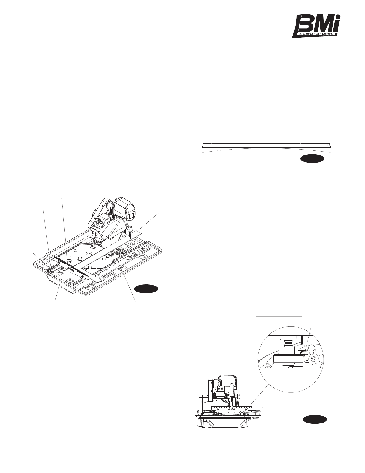
REALIGNMENT
Method 1:
This procedure deals with the most common source of mis-
alignment that occurs when the guide rails are not parallel
with the blade.
1. Set the cutting depth such that the blade passes through
the table, not over.
2. Place a straight edge (i.e. carpenter’s square) on the
cutting table as shown in figure 8.
3. Loosen the left and right guide rails by loosening the
fasteners found at the ends of the rail. (see figure 8)
The left rail should be slightly loose, so there is not too
much play during adjustments, but the right rail should
move freely.
4. Make sure the short portion of the straight edge is placed
flush against the ruler guide. Adjust the left guide rail
so that the front and rear edges of the blade touch the
straight edge, although a tolerance of 0.1mm between
the front and rear edges is allowed. Perform this adjust-
ment along the entire length of the straight edge.
5. Position the table as close to the user as possible.
Place the straight edge flush against the ruler guide and
blade. Without holding onto the straight edge, gently
move the table towards the rear of the saw and then
back. Observe any gaps that may appear between the
straight edge and blade or between the straight edge
and ruler guide. A gap exceeding the allowed tolerance
Ruler Guide
Right Guide Rail
Fastener
Left Guide
Rail
Straight Edge
Front of the Saw
figure 8
means that the table is not moving parallel to the blade;
hence, further adjustments as outlined in step 4 will be
required. However, if scenario A or B described below
occurs, other adjustments may be required instead.
A. If the straight edge only touches the blade when
the table is positioned midway along the rail or
at the ends of the rail, then the rail may be de-
formed (i.e. bowed). (see figure 9) Perform test
cuts to determine if the rail should be replaced.
Typically a bowing displacement of up to 0.2mm
will not affect cutting accuracy.
B. If the straight edge touches both edges of the
blade intially, but shifts apart as the table travels
along the rail, proceed to method 2 below.
6. Tighten the fasteners at both ends of the left rail.
7. Adjust the right guide rail so that the horizontal rollers
underneath the table engage the rail as shown in figure
10. In most cases the rollers will not have to be verti-
cally adjusted. Spacing between rails must be equidis-
tant at all points to ensure that they are parallel. Once
adjustments are made, lightly tighten the fasteners on
the right rail and move the table back and forth. If the
table binds against the rail at any point, adjust spacing
accordingly until the table moves smoothly.
8. Tighten the fasteners at both ends of the right rail.
If alignment has been achieved do not proceed to method
2.
figure 9
Leave hairline gap
between rail and roller
Leave a 1⁄32″
(1mm) gap
figure 10

IDP1010 • Owner’s Manual
13
3. If the table shifts to the right as it travels away from the
user, a shim needs to be added to the guide roller fur-
thest from the ruler guide. On the other hand, if the
table shifts to the left, a shim needs to be added to the
guide roller closest to the ruler guide. Remove the ap-
propriate guide roller to insert a shim between the roller
and table, then reattach. (see figure 14) Depending on
the severity of the shift, more than one shim may be
required.
4. After adding shim(s), mount the table onto the guide rails
by reversing the instructions in step 2. Move the rails
toward each other to engage the horizontal rollers to the
right guide rail as shown in figure 10. Realign the table
to the blade using method 1. Check to see if any shifting
persists. A shift tolerance of 0.2mm is allowed. A shift
in excess of that will require further adjustment—repeat
step 3.
5. Once alignment is successful, replace saw back into the
water tray.
Method 2:
This procedure corrects another source of misalignment
that occurs when the table’s orientation is not parallel with
the guide rails.
1. Lift the saw up from within the water tray and place it on
a flat level surface. Use the universal wrench to loosen
(but not remove) the fasteners from either end of both
guide rails. Move each rail away from the other, so that
the horizontal rollers are clear of the right guide rail. (see
figure 11)
2. Remove rubber cap A on the left side of the table. Loos-
en the exposed lock nut using a 13mm socket wrench.
Use a flat screwdriver to turn the shaft of the roller clock-
wise to lower it by approximately 3/8”. (see figure 12)
Evenly lift up the table to disengage the guide rollers
from the left guide rail. Once the guide rollers are clear,
shift the table to the right to clear the left horizontal roller
of the rail. Remove the table from the guide rails. (see
figure 13)
Horizontal
Roller
Flat Roller
figure 14
Shim
Guide Roller
Rubber Cap B Flat Screw Driver
Size 13mm
Socket
Wrench
figure 12
Rubber Cap A Rubber Cap C
figure 11
Loosen Fasteners
Right Guide Rail
Clearance
Horizontal Roller
Guide Roller Horizontal Roller
figure 13
1
2
Left Guide Rail

14
LEVELING ADJUSTMENT
This procedure levels the table so that it is perpendicular to
the blade and flush against the rails.
1. Remove rubber caps B and C on the right side of the
table. Loosen the exposed lock nuts using a socket
wrench. Next, use a flat screwdriver to turn the shaft
of the rollers clockwise. (see figure 12) This will lower
the horizontal rollers to allow room for adjusting the flat
rollers.
2. Loosen the socket bolts on the flat roller plate so that the
roller can swing freely about one bolt. (see figure 15)
Do this for both flat roller plates.
3. Hold the table against the guide rails. The flat rollers
should reposition themselves to maintain contact with
the guide rails. If the table is not perpendicular to the
blade, lift the right side of the table instead to obtain the
proper angle. A square tool will be required to confirm
the angle. Tighten the socket bolts. Check the table for
play. Repeat step 2 if some play is still present.
4. Restore the horizontal rollers to their original positions
as shown in figure 10 by reversing the instructions in
step 1. Be sure to tighten the lock nuts and replace the
rubber caps.
Flat rollers rotate in this manner
figure 15

IDP1010 • Owner’s Manual
15
ELECTRICAL WIRING DIAGRAM
RECOMMENDATIONS
• It is recommended that a 15 amp circuit be used while
operating this saw. This will prevent any loss of power
or interruption.
• Always plug saw as close as possible to the power
source while operating. This will allow you to receive
optimum electricity.
EXTENSION CORD CHART
IDP1010
Power 2 HP
Volts 115 V
Amps 13 A
Motor RPM 3000 RPM
Cycle 60 Hz
Phase 1
Wire Gauge Length of Cord
No. 12 25’
No. 10 50’
No. 8 75’
Electrical Specifications
To avoid permanent motor damage you must use the cor-
rect extension cord. Never use more than one extension
at a time. Follow the chart below for proper size.
WARNING:

16
Troubleshooting
Problem Possible Cause Solution
Machine does not run when switched
on
Power cord not properly fixed/
plugged in
Check that the machine is properly
connected to the power supply
Power cord defective Have the power cord checked, re-
place if necessary
Main power switch defective Have the main power switch checked
and replace if necessary by a quali-
fied electrician
Loose electrical connection inside
the electric system
Have the whole electric system of
the machine checked by a qualified
electrician
Motor defective Have the motor checked and re-
placed if necessary by a qualified
technician
Motor stops (power cut out) Too much pressure exerted while
cutting
Exert less pressure when cutting
Incorrect specification for saw blade Use a saw blade which corresponds
to the material being cut
Saw has a defective electric system Have the electric system of the saw
checked by a qualified technician
Poor machine performance, little
power
Power cord/extension cable too long
or cable still wound up inside cable
drum
Use a power cord/extension cable of
the rated length, use a cable drum
with cable fully extended
Power network is insufficient Observe the electrical ratings of the
machine and connect it only to a
power network which complies with
these ratings
Drive motor no longer runs at rated
speed (RPM)
Have the motor checked by a quali-
fied electrician and have it replaced if
necessary

IDP1010 • Owner’s Manual
17
Problem Possible Cause Solution
Insufficient flow of cooling water or
no cooling water at all
The pump draws air Fill the container with water
Filter clogged Clean the filter of the pump
Pump wheel of the immersion pump
blocked by dirt
Disassemble the immersion pump
and clean
Irregular run of the saw blade Poor tension in the blade material Return the saw blade to the manu-
facturer
Saw blade wobbles when running Saw blade is damaged or bent Have the saw blade aligned /
flattened
Clean the receiving flange
Solder the diamond segments of the
old blade onto another saw blade or
use a new blade
Flange of the saw blade is damaged Replace the saw blade flange
Shaft of the motor is bent Replace the electric motor
Diamond segment becomes loose Overheating of the saw blade; cool-
ing water not sufficient
Have the diamond segment soldered
on the blade again; ensure optimum
flow of cooling water
Excessive wear Wrong type of saw blade Use harder saw blades
Shaft of motor causes wobbling Have bearings of the motor or the
motor replaced
Overheating Ensure optimum flow of cooling
water
Cracks in or near the diamond seg-
ment
Saw blade too hard Use a softer blade
Fixed flange is worn out Replace the fixed flange
Motor shaft bearing Replace the bearing of the motor
shaft

18
Problem Possible Cause Solution
Saw blade is blunt Saw blade type is unsuitable for the
material being cut
Use appropriate type of saw blade
Saw blade type is unsuitable for the
machine performance
Saw blade too hard
Diamond segments are blunt Sharpen the diamond saw blade
Appearance of cut is not optimal Poor tension in the blade material Return the saw blade to the manu-
facturer
Too much load placed on the saw
blade
Use a suitable saw blade
Diamond segments are blunt Sharpen the saw blade
The center hole in the saw blade has
become wider due to wear
The saw blade has slipped on the
motor shaft when running
The arbor of the saw blade must be
fitted with an appropriate adaptor
ring
Check the receiving flange and have
it replaced if necessary
Saw blade shows blooming colors Saw blade overheating due to a lack
of cooling water
Ensure an optimum flow of cooling
water
Lateral friction when cutting The material feed is too high; pro-
ceed more slowly
Grinding marks on the saw blade Material is not being fed parallel to
the saw blade
Ensure that the direction of feed is
absolutely parallel to the saw blade
Adjust the roller table or have it
adjusted
Poor tension in the blade material Have the saw blade tensioned
Too much load on the saw blade The material feed is too high, pro-
ceed more slowly

IDP1010 • Owner’s Manual
19
Replacement Parts List
MAIN ASSEMBLY
1. Frame assembly 100125
2. Cutting head assembly 100127
3. 10” Blade guard assembly 100129
4. 848L Left/Right rail 100131
5. 230 gal/hr Water pump 100132
6. TX02 Cutting table 100133
7. 10” (254mm) General purpose blade
8. Dia 5/8” (15.9mm) Universal flange 100136
9. 5/8”-11 UNC Nut 100137
10. M8 Spring washer 100080
11. M10 Spring washer 100138
12. M8 x 1.25 x 20L knob 100139
13. D30 Rubber plug 100140
14. M8 x 1.0 Nut 100086
15. M8 Narrow washer 100141
16. M8 x 1.25 x 16L Hex bolt 100109
17. M8 Regular washer 100142
18. ABS Water tray 100143
19. Rear drip tray 100144
DESCRIPTION PART NO DESCRIPTION PART NO
2 17 10
6
16
10
15
4
13
19
18
5
1
11
12
14 3 11 12 7 8 9
Table of contents
Other BMI Saw manuals


