BMS BPA-5CC-7 User manual

BPA-5CC-7 1.99–2.5 GHz 5W Power Amplifier
Installation and Operation Manual
Doc #6051407907 Rev -
Broadcast Microwave Services, Inc.
12367 Crosthwaite Circle
Poway, CA 92064
Tel: +1 (858) 391-3050 | Toll-free (US): 800-669-9667
Fax: +1 (858) 391-3049
bms-inc.com

© 2008 All rights reserved. Broadcast Microwave Services, Inc.
Specifications are subject to change without prior notice. This document contains confidential
information and is intended for customer use only. It cannot be duplicated without prior
authorization from BMS.
BPA-5CC-7 1.99–2.5GHz 5W Power Amplifier Manual | Doc #6051407907 Rev -
Broadcast Microwave Services, Inc. i
WARNING! RF RADIATION EXPOSURE HAZARD
•This warning is provided by Broadcast Microwave Services
(BMS) Inc. for safety purpose.
•The following information help to reduce the risk of RF
exposure hazard.
FCC Limit of RF Exposure
According to the Federal Communication Commission (FCC), the Maximum Permissible
Exposure (MPE) for RF radiation has been set to 1.0 mW/cm2 for the 1.99–2.5GHz linear
power amplifier with maximum of 5 watts output power (OET Bulletin 65) for operation under
part 90 of FCC regulations (47CFR90).
The 1.99–2.5GHz power amplifier (PA) may be a part of a non-broadcast transmitter, and
without an antenna it will not create RF exposure (power density) exceeding the 1.0 mW/cm2
FCC limit. However, a high-gain antenna such as a parabolic dish will greatly enhance the PA
output power density beyond the MPE limit of 1.0 mW/cm2.
In this situation a minimum distance from the antenna must be calculated in order to keep the
MPE always below the safety limit. The calculation has been done for the PA based on the
formula mentioned in OET Bulletin 56. The calculations have been done for different
commonly used antenna in the BAS and Public Safety/Law enforcement applications.
Figure 1 shows the plot of the minimum exposure distance for 5dBi, 16dBi, and 30dBi
antennas, assuming the PA transmits the maximum power of 5 W. The minimum exposure
distances are found from the cross points of the exposure graphs (for various antennas) with the
line of maximum permissible exposure (i.e. 1mW/cm2). Notice that the numbers in Figure 1
predict the worse case scenario, which is straight in front of the antenna (exposing the
antenna’s main lobe). Obviously the side-lobe exposures are well below these numbers as the
radiation intensity drops dramatically on the side lobes. The antenna used for this transmitter
must not be co-located or operating in conjunction with any other antenna or transmitter.
The user and installer must provide suitable operating procedures and warnings to meet MPE
requirements when operating the PA into an antenna.
Operational Limits and User Access
CAUTION!
•Do not 5A peak load in optional accessory equipment!
•Do not exceed -12dBm average input power!
NOTE
There are NO user adjustable components in the amplifier!

BPA-5CC-7 1.99–2.5GHz 5W Power Amplifier Manual | Doc #6051407907 Rev -
Broadcast Microwave Services, Inc. ii
Contents
1Product Description...........................................................................................................................1
1.1 RF Exposure ............................................................................................................................1
1.2 Linear Power Amplifier (BPA-5CC-7) Description.....................................................................2
1.3 Specifications ...........................................................................................................................3
1.4 Applications..............................................................................................................................3
2Installation ..........................................................................................................................................5
2.1 Installation Notes and Wiring Diagram .....................................................................................5
3Warranty..............................................................................................................................................8
3.1 Customer Service and Contact Information..............................................................................8
4Appendix.............................................................................................................................................9
4.1 Labels.......................................................................................................................................9
List of Figures
Figure 1. Estimated RF exposure................................................................................................................1
Figure 2. Parts locations..............................................................................................................................2
Figure 3. External view................................................................................................................................2
Figure 4. Typical application block diagram.................................................................................................4
Figure 5. Typical application........................................................................................................................4
Figure 6. Pin-out for PTO connector, MS3112E14-5P.................................................................................5
Figure 7. PA wiring diagram ........................................................................................................................6
Figure 8. PA chassis footprint......................................................................................................................6
Figure 9. PA chassis dimensions.................................................................................................................7
Figure 10. BMS product label......................................................................................................................9
Figure 11. FCC label ...................................................................................................................................9

BPA-5CC-7 1.99–2.5GHz 5W Power Amplifier Manual | Doc #6051407907 Rev -
Broadcast Microwave Services, Inc. 1
1 Product Description
1.1 RF Exposure
In order the keep the RF exposure within the FCC limit, it is necessary to maintain the safe
distance from the antenna. The results shown in Figure 1 can be summarized in the following
table:
Antenna Gain (dBi) Minimum permissible distance from antenna (cm)
5 45
16 125
30 626
Notice the above table indicates worst-case situation (straight in front of the antenna).
Figure 1. Estimated RF exposure

BPA-5CC-7 1.99–2.5GHz 5W Power Amplifier Manual | Doc #6051407907 Rev -
Broadcast Microwave Services, Inc. 2
1.2 Linear Power Amplifier (BPA-5CC-7) Description
The BPA-5CC-7 is a linear power amplifier suitable for OFDM with 5W maximum RF power
and operates at 1.99GHz to 2.4835GHz. This PA is used for increasing transmission range by
boosting a 2GHz transmitter’s power to 5W maximum. The PA may be used from 1.99 to
2.50GHz for non-US applications or for special grandfathered frequency allocations.
Figure 2. Parts locations
Figure 3. External view
RF Output DC Voltage RF Input
Fans
Product Label
FCC Label

BPA-5CC-7 1.99–2.5GHz 5W Power Amplifier Manual | Doc #6051407907 Rev -
Broadcast Microwave Services, Inc. 3
1.3 Specifications
Frequency 1.99 – 2.50 GHz *
Output Power 5W max.
Input Voltage 28 VDC
Input Current 5 to 6 Amp @ 28VDC
Input RF Power -12 dBm max.
Gain @ -12 dBm input 52 dB
Gain Flatness ± 1.0 dB over 500 MHz
Gain vs. Temperature ± 1 dB over temperature
Operating Temperature -20° to +50°C
Storage Temperature 40° to +90°C
Dimensions 9.5” x 5” x 3”
Weight 8 lbs
RF Input Connector Type “N”
RF Output Connector Type “N” Isolator Protected
* FCC certification for 2.45–2.4835GHz under Part 90
This product supports the following Emission Designators:
FCC ID Modulation Emission Designators
CNVHCII-5-7 Digital 6M0W7D, 7M0W7D, 8M0W7D
Operation under FCC rule part: 74, 90
1.4 Applications
Portable digital video COFDM transmitters, such as the BMS 2GHz CarryCoder II, are used
behind the camera in security and law enforcement live video transmission. These transmitters
can only provide a medium RF power (e.g. < 1W), limiting the distance between the event site
and relay station. To extend the transmission range, an external amplifier is needed to boost the
transmitter power in order to compensate the path loss and ensure the acceptable Received
Signal Level (RSL) at the destination. The BPA-5CC-7 will increase the RF power to the
maximum 5W without adding spurious signals and distortions to the transmitter output. The
power amplifier output is directly connected to the 2GHz transmitting antenna.
A typical transmitter application of the 1.99–2.5GHz power amplifier is shown in Figure 5. A
practical application is shown in Figure 6. The output of the PA is directed to the transmitting
antenna located on the roof of a mobile vehicle. The receiver antenna can be located on a mast
to result in better coverage over longer distance.

BPA-5CC-7 1.99–2.5GHz 5W Power Amplifier Manual | Doc #6051407907 Rev -
Broadcast Microwave Services, Inc. 4
Figure 4. Typical application block diagram
Figure 5. Typical application

BPA-5CC-7 1.99–2.5GHz 5W Power Amplifier Manual | Doc #6051407907 Rev -
Broadcast Microwave Services, Inc. 5
2 Installation
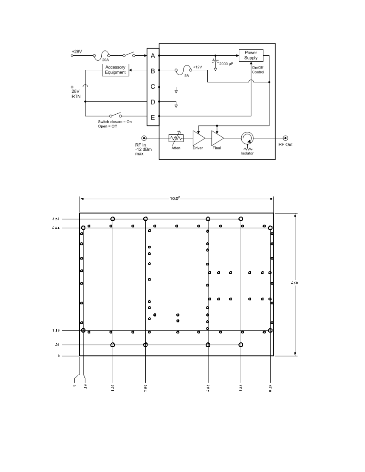
2.1 Installation Notes and Wiring Diagram
The power amplifier is wired to accessory equipment according to the pin-out and wiring
diagrams in Figure 6 and Figure 7. Chassis dimensions are provided in Figure 8 and Figure 9.
Be aware of the following critical installation points:
1. 28V breaker should handle 15A to 20A surge, 8A average, and 0.8 joules in-rush to charge
the input capacitor.
2. Accessory +12Vout is internally fused at 5A.
CAUTION!
•Do not 5A peak load in optional accessory equipment!
NOTE
There are NO user adjustable components in the amplifier!
3. Output power is proportional to input power. Do not exceed the PA’s rated output power
for OFDM.
CAUTION!
•Do not exceed -12dBm average input power!
4. The PTO connector pin-out is as follows. See Figure 6.
Pin A = +28VDC input
Pin B = +12V fused output
Pin C = 28 VDC Return
Pin D = 12 VDC Return
Pin E = Power ON/OFF control
D
EB
C
A
Figure 6. Pin-out for PTO connector,
MS3112E14-5P
BPA-5CC-7 1.99–2.5GHz 5W Power Amplifier Manual | Doc #6051407907 Rev -
Broadcast Microwave Services, Inc. 6
Figure 7. PA wiring diagram
5. The PA’s mounting footprint and envelope are shown in Figure 8 and Figure 9.
Figure 8. PA chassis footprint

BPA-5CC-7 1.99–2.5GHz 5W Power Amplifier Manual | Doc #6051407907 Rev -
Broadcast Microwave Services, Inc. 7
Figure 9. PA chassis dimensions

BPA-5CC-7 1.99–2.5GHz 5W Power Amplifier Manual | Doc #6051407907 Rev -
Broadcast Microwave Services, Inc. 8
3 Warranty
BMS warrants that, at time of delivery, the product will be free from defects in materials and
workmanship, provided the equipment or system is installed, operated and maintained in
accordance with the Operation and Maintenance manual or such other BMS documentation as
may be applicable. Any such defect reported to BMS within two years, BMS will take
reasonable and prompt action to repair or replace such equipment.
Should any of the components be defective, please contact BMS immediately. Please have the
following information available so we can best serve you.
•customer name
•contract number
•BMS model number
•serial number
•detailed description of problem
•name of contact person.
•contact information such as phone number and/or email address.
•return information
Much of this information is printed on the equipment’s product label.
Defective components under BMS warranty will be repaired/replaced promptly at the
discretion of BMS. A PO is required BEFORE repairs can begin on items no longer under
warranty.
Note: All goods returned for service require an RMA number. Any goods received without an
RMA number may not be processed in a timely manner. Please contact BMS for an RMA
number.
3.1 Customer Service and Contact Information
Broadcast Microwave Services, Inc.
12367 Crosthwaite Circle
Poway, CA 92064
Tel: +1 (858) 391-3050 | Toll-free (US): 800-669-9667 | Fax: +1 (858) 391-3049
BPA-5CC-7 1.99–2.5GHz 5W Power Amplifier Manual | Doc #6051407907 Rev -
Broadcast Microwave Services, Inc. 9
4 Appendix
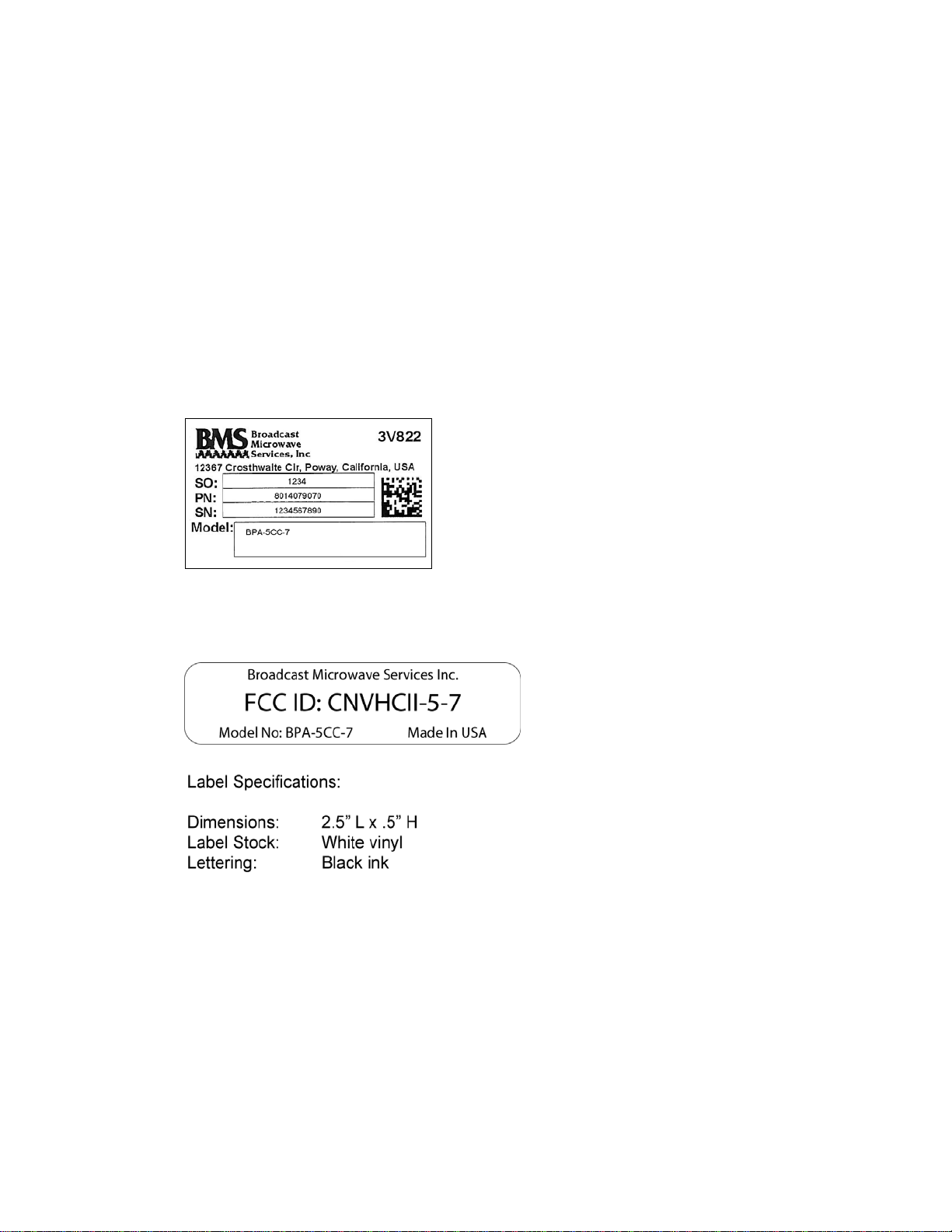
4.1 Labels
The following label diagrams are included in this appendix for reference.
Figure 10. BMS product label
Figure 11. FCC label
Table of contents


