PAGE 4
Functional Description
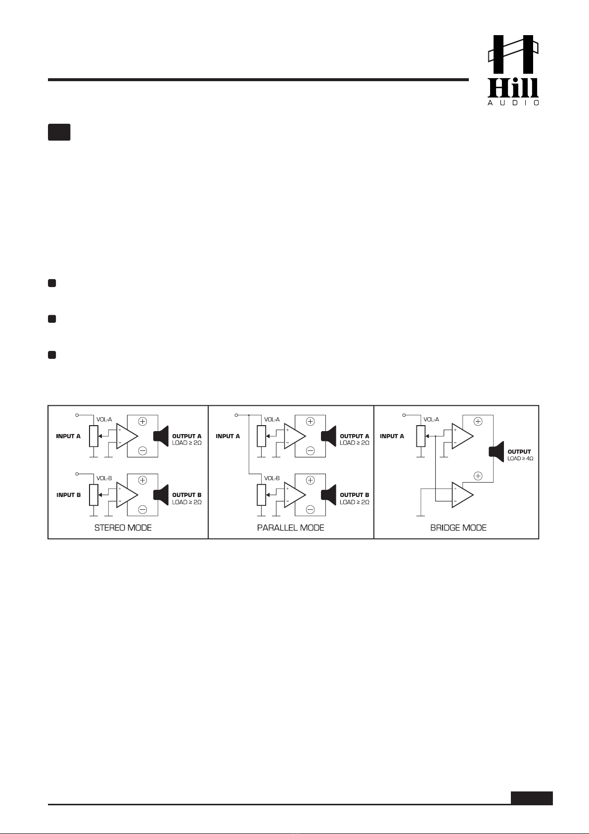
The QPA2800 is an analog audio power amplifier with four channels (2 pairs x2), where each pair can
be used with independent input signals (stereo mode), identical input signal (parallel mode) or in
bridge mode as a single channel amplifier. It displays all relevant status information on a 3-color front-
panel display and offers a multitude of input and output connections for great application versatility.
2
1
3
4
7
8
6
5
AC inlet. This is a PowerCon™-compatible power inlet. Use a cable equipped with a matching
PowerCon™ compatible plug only. Make sure voltage and frequency stated and set on the unit
comply with your local AC supply.
Circuit breaker. This is a resettable breaker to protect the unit and the AC supply from any
malfunctions. To reset a tripped circuit breaker, simply switch the unit off, set the fuse breaker
back to ON status and re-power the unit. If the breaker trips again, hand over the unit to quali-
fied service personnel.
Speakon™-compatible speaker outputs for stereo and parallel mode operation (see explana-
tion in chapter “setting the operation mode”). Connect your speaker leads with matching
connectors here, using the 1+ and 1- terminals inside the plug. For 4-lead cabling with both
the A and B output running through the same 4-lead cable, use the 2+ and 2- terminals inside
the plug inserted to the A1 and A2 outputs to achieve proper connections for B1 and B2
outputs. Alternatively, speakers can be connected to the terminal strip speaker outputs (4).
Do not connect speakers to both these Speakon™-compatible outputs and the terminal strip
outputs (4) at the same time.
Terminal strip outputs for stereo, parallel and bridge mode operation (see explanation in
chapter “setting the operation mode”). Connect your speaker leads here, using one speaker
lead pair each connected to the + and - outputs of each channel respectively. If the unit is used
in bridge mode, use the ouputs A1+ and B1+ for the connection of one speaker, and the
outputs A2+ and B2+ for the connection of another speaker. You can also use one channel
pair in stereo/parallel configuration and the other pair in bridge configuration, as require-
ments demand. Do not connect speakers to both these terminal strip outputs and the relative
Speakon™-compatible outputs (3) at the same time.
Fan ventilation apertures. The amplifier pushes the cooling air out of these apertures. Make
sure these remain unobstructed. For more information about cooling, see the chapter “Instal-
lation, Cooling and Wiring”.
Channel signal inputs. These are a balanced terminal blocks designed to accept matching
connectors which carry input signals for channels A1/A2 and B1/B2 respectively. Channel
B1/B2 inputs remain unused in parallel and bridge operation modes (see explanation of
operation modes in chapter “setting the operation mode”). Alternatively, use the Combo inputs
(7) to connect input sources. Do not connect input sources to these connectors and the
Combo inputs (7) at the same time. Note that when using these inputs the lead assignment is
mirrored between A1&B1 vs. A2&B2.
Channel signal inputs. These are Combo (XLR+TRS) connectors for input signals to channels
A1/A2 and B1/B2 respectively. Channel B1/B2 inputs remain unused in parallel and bridge
operation modes (see explanation of operation modes in chapter “setting the operation
mode”). Alternatively, use inputs (6) to connect input sources. Do not connect input sources to
these connectors and the inputs (6) at the same time.
Channel volume controls. Depending on the chosen operation mode (see explanation of opera-
tion modes in chapter “setting the operation mode”), these 41-click precision potentiometers
control either all channel volumes individually (in stereo and parallel modes) or channel A1/A2
volume controls are active while channel B1/B2 volume controls are disabled (in bridge
mode).
USER MANUAL - QPA2800 AMPLIFIER