BMW R 1200 RT-P User manual

Welcome to BMW
We congratulate you on your de-
cision to equip your vehicle with
this two-way radio system. You
will find it a quick and easy gate-
way for using the two-way radio
devices you connect to it.
Use these operating instructions
to familiarise yourself with the
system. If you have further
questions, your authorised
BMW Motorrad dealer will gladly
provide advice and assistance.
We hope that your perusal of
these operating instructions will
be enjoyable and instructive and
that all your journeys will be
pleasant and safe
BMW Motorrad.
01 41 7 686 141
*01417686141*
*01417686141*
*01417686141*

Table of Contents
You can also consult the index
at the end of these operating in-
structions if you want to find a
particular topic or item of inform-
ation.
1 General instructions ... . 5
Deviations from these instruc-
tions.......................... 6
Abbreviations and
symbols...................... 6
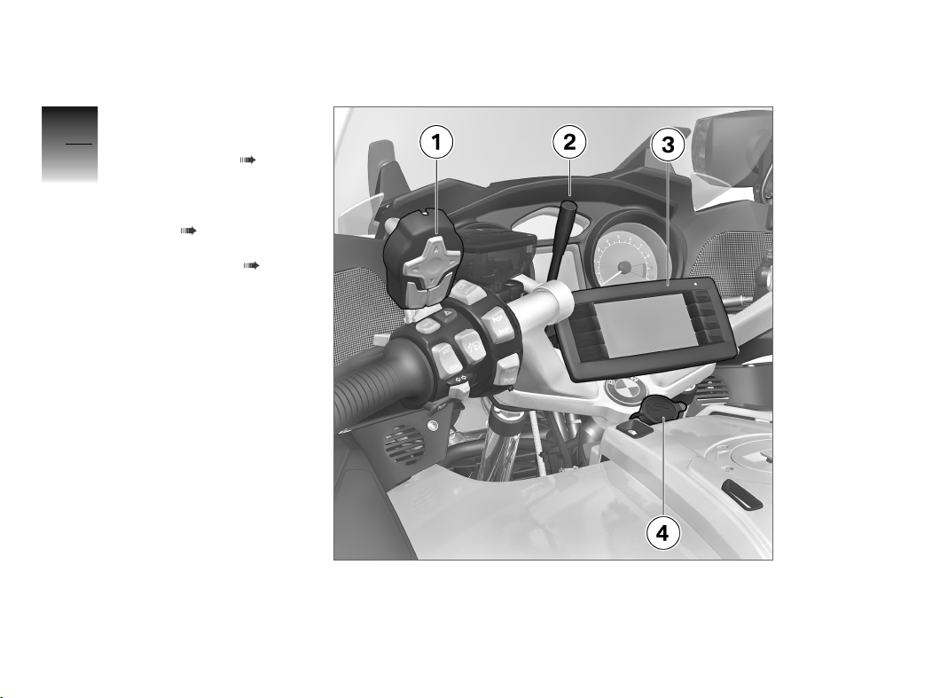
2 General views .. .. .. .. .. .. 9
Controls with satellite
switch....................... 10
Controls with extra
switches..................... 11
Two-way radio box . . . . . . . . . . 12
Satellite switch . . . . . . . . . . . . . . 13
Extra switch ................. 15
Softkeys on the operating
panel........................ 16
Status indicators of the op-
erating panel . . . . . . . . . . . . . . . . 18
3 Operation................ 19
Main switch ................. 20
Switching system on/off . . . . . 20
Operating principle . . . . . . . . . . 20
4 Main menu .............. 23
Overview, main menu . . . . . . . 24
Settings for analog radio
transmissions. . . . . . . . . . . . . . . . 25
Settings for digital radio
transmissions. . . . . . . . . . . . . . . . 25
Emergency call . . . . . . . . . . . . . . 27
Channel selection for analog
radio transmissions . . . . . . . . . . 28
Group selection for digital
radio transmissions . . . . . . . . . . 29
Volume...................... 32
5 Messages ............... 35
New message............... 36
Selecting message . . . . . . . . . . 36
Reading message . . . . . . . . . . . 36
6 One-to-one connec-
tions ..................... 39
Selecting party to call from
presetslist .................. 40
Selecting party to call from
favourites list . . . . . . . . . . . . . . . . 40
Selecting party to call
from list of recent
connections................. 41
Accepting and closing in-
comingcalls................. 41
7 Options .................. 43
Options, overview . . . . . . . . . . . 44
Administration software . . . . . 45
Adjusting display bright-
ness......................... 45
System settings . . . . . . . . . . . . . 45
Changing system
settings ..................... 46
Set status and emergency-
call system .................. 46
Changing FMS code . . . . . . . . 46
Talk via public address sys-
tem ......................... 47

Switch active device . . . . . . . . 48
Reporting duty status . . . . . . . 48
Switch radio bridge on/
off........................... 49
Bluetooth.................... 49
8 VOPTA................... 51
No VOPTA assigned . . . . . . . . 52
Setting VOPTA . . . . . . . . . . . . . 52
9 Gateway / repeater . .. .. 55
Setting gateway or
repeater..................... 56
10 Service software . .. .. . 59
Cloning parameters . . . . . . . . . 60
Exporting configuration
data ......................... 61
Sending configuration
data ......................... 61
11 Administration soft-
ware .................... 63
Settings, digital radio trans-
missions..................... 64
System settings . . . . . . . . . . . . . 64
Setting audio level . . . . . . . . . . 65
Adjusting input level for
gooseneck microphone . . . . . 66
Resetting settings for audio
system ...................... 66
Set status and emergency-
call system .................. 67
12 Installation test .. .. .. . 69
Audio components . . . . . . . . . . 70
Starting installation test . . . . . 70
13 Index ................... 72


General instructions
Deviations from these instructions . . . 6
Abbreviations and symbols . . . . . . . . . . 6
1
5
z
General instructions

Deviations from these
instructions
These operating instructions de-
scribe a two-way radio system
with one digital and one analog
two-way radio device. Differ-
ences between these instruc-
tions and the system may be
encountered if only one two-
way radio is connected or if the
connected devices do not sup-
port functions described here.
Differences are also possible if
changes to the on-board com-
puter are made via the adminis-
tration software.
The R 1200 RT was used by
way of example for generation of
the graphics. The layout of the
components described may differ
for other BMW Motorrad models,
but the functions are identical.
Abbreviations and
symbols
CAUTION indicates a haz-
ard with a low degree of
risk which, if not avoided, could
result in slight or moderate injury.
WARNING indicates a
hazard with a medium de-
gree of risk which, if not avoided,
could result in death or serious
injury.
DANGER indicates a haz-
ard with a high degree of
risk which, if not avoided, will res-
ult in death or serious injury.
ATTENTION marks pre-
cautionary statements that
you must comply with in order to
protect your product from dam-
age.
NOTICE marks general or
technical statements con-
taining information that is useful
for better operation, checking or
adjustment procedures and for
upkeep.
Indicates the end of an
item of information.
Instruction.
Result of an activity.
Reference to a page with
more detailed informa-
tion.
Indicates the end of a
passage relating to spe-
cific accessories or items
of equipment.
Tightening torque.
Technical data.
1
6
z
General instructions

BOS Behörden und Organ-
isationen mit Sicher-
heitaufgaben / agencies
and organisations tasked
with security duties.
Umbrella term applied to
civil units authorised to
use blue flashing lights
in public traffic (e.g. po-
lice, fire-fighters, emer-
gency services)
DMO Direct Mode Operation.
Operating mode
between two or more
partners independent of
network infrastructure
PA Public Address system.
Acoustic system used
primarily for spoken an-
nouncements
FMS Funkmeldesystem / ra-
dio alert system.
Audio-frequency trans-
mission system in BOS
wireless communica-
tions for agencies and
organisations
FuG Funkgerät / radio unit.
An FuG number is as-
signed to tested devices
for use by official agen-
cies, for example FuG 8
is the number for use in
motor vehicles.
GSM Global System for Mo-
bile standard.
Standard for fully digital
mobile wireless net-
works
PTT Push-to-talk.
Button on two-way ra-
dio devices for toggling
between receive and
transmit
SDS Short Data Service.
Service for transmitting
short messages in the
TETRA wireless network
SMS Short Message Service.
Service for transmitting
text messages in mobile
wireless and landline
networks
TE-
TRA
Terrestrial Trunked Ra-
dio.
Encrypted BOS radio
standard
1
7
z
General instructions

TMO Trunked Mode Opera-
tion.
Operating mode
between two or more
partners in the network
infrastructure with
TETRA digital radio
VO-
PTA
Variable operativ-takt-
ische Adresse / variable
operational-tactical ad-
dress.
Contains additional in-
formation about the
identity of a user
1
8
z
General instructions

General views
Controls with satellite switch . . . . . . 10
Controls with extra switches . . . . . . . 11
Two-way radio box. . . . . . . . . . . . . . . . . . 12
Satelliteswitch...................... 13
Extraswitch......................... 15
Softkeys on the operating panel . . . . 16
Status indicators of the operating
panel ............................... 18
2
9
z
General views

Controls with satellite
switch
1Satellite switch ( 13)
2Gooseneck microphone
3Operating panel:
Softkeys on the operating
panel ( 16)
Status indicators of the
operating panel ( 18)
4Quick-disconnect coupler
for helmet system
2
10
z
General views

Controls with extra
switches
1Extra switch ( 15)
2Gooseneck microphone
3Operating panel:
Softkeys on the operating
panel ( 16)
Status indicators of the
operating panel ( 18)
4Quick-disconnect coupler
for helmet system
2
11
z
General views

Two-way radio box
1Two-way radio 1
2Two-way radio 2
3On-board computer
4Main switch ( 20).
2
12
z
General views

Satellite switch
1Select and set menu
items.
Direct access to
Adjust the volume ( 32).
2Select and set menu
items.
Direct access to
Reporting duty status
( 48).
3Select and set menu
items.
Menu selection ( 20)
Direct access to
Adjust the volume ( 32).
4Select and set menu
items.
Direct access to
Reporting duty status
( 48).
5PTT2 button for two-way
radio 2 or for the speakers
6PTT1 button for two-way
radio 1 or two-way radio 2
2
13
z
General views

7Confirmation of the set-
tings
2
14
z
General views

Extra switch
1Multi-Controller:
Select and set menu
items.
Direct access to
Adjust the volume ( 32).
Reporting duty status
( 48).
F1 PTT1 button for two-way
radio 1
F2 PTT2 button for two-way
radio 2
F3 PTT3 button for speakers
NOTICE
Special functions can be as-
signed to function buttons F1
to F4, depending on equipment
fitted and customer request (see
the section entitled "Technical
data" in the manual for the spe-
cial vehicle).
2
15
z
General views

Softkeys on the
operating panel
F1 Menu selection ( 20)
F2 Settings for radio 1 (here:
analog two-way radio)
F3 Settings for radio 2 (here:
digital two-way radio)
F4 Activating emergency call
( 27)
F5 System settings ( 45)
In standby mode: switch
system ON
F6 Channel selection for ana-
log radio transmissions
( 28)
F7 Group selection for di-
gital radio transmissions
( 29)
F8 Adjust the volume ( 32).
NOTICE
F2-F4 and F6-F8 are softkeys,
their functions vary from menu to
menu. The functions described
2
16
z
General views

here are those that correspond to
the main menu. 2
17
z
General views

Status indicators of the
operating panel
1Duty status ( 48)
2Helmet system connected
3Bluetooth active ( 49)
4Radio bridge active
( 49)
5Error diagnosed
6PTT1 operates radio
1 (PPT2 operates PA)
( 47)
7Transmit, radio 1
8Receive radio 1
9Receive radio 2
10 Transmit, radio 2
11 PTT1 operates radio
2 (PPT2 operates PA)
( 47)
12 Volume ( 32)
13 One-to-one connection
menu active ( 40)
14 Messages menu active
( 36)
15 Main menu active
2
18
z
General views

Operation
Mainswitch......................... 20
Switching system on/off . . . . . . . . . . . . 20
Operating principle. . . . . . . . . . . . . . . . . . 20
3
19
z
Operation

Main switch
The main switch for the on-board
computer is inside the two-way
radio box.
Switch off the main switch
when you park the motorcycle.
NOTICE
The on-board computer draws
power from the auxiliary bat-
tery even when the ignition is
OFF. With the engine stopped,
do not leave the main switch
ON for longer than absolutely
necessary.
NOTICE
On the R 1200 RT (K52), the
power supply to the on-board
computer is automatically
switched off 120 minutes after
the engine is stopped so as not
to place unnecessary strain on
the auxiliary battery.
Switching system on/
off
Press and hold down F4 un-
til the system switches off
(standby mode).
You can reactivate the system
by pressing F5.
To switch the system off com-
pletely press the main switch
of the on-board computer.
You cannot switch the system
on again by pressing F5.
Operating principle
F1
On the topmost menu level (all
symbols 1visible), pressing F1
takes you to the next menu.
In a submenu (only the symbol
for the active menu is visible),
pressing F1 takes you back to
the topmost menu.
F2 - F4
The functions of F2 -F4 change
from menu to menu and are de-
scribed accordingly in the sec-
tions below. The current function
3
20
z
Operation
Table of contents