Boiler Company Burnham 3 Series User guide

Gas Boiler Wiring & Application Guide
U.S. Boiler Company
08/23/13
1
Gas Boiler Controls
Wiring & Application Guide
Featuring Burnham®Brand IQ Boiler Control
and Intelligent Hydronic Control Systems
ES2™ ESC™ Series 3™ Series 2™
boiler
control Intelligent
Hydronic Control
©2013 U.S. Boiler Company

Gas Boiler Wiring & Application Guide
U.S. Boiler Company
08/23/13
2
Table of Contents
1.0 Introduction ........................................................................................................................... 3
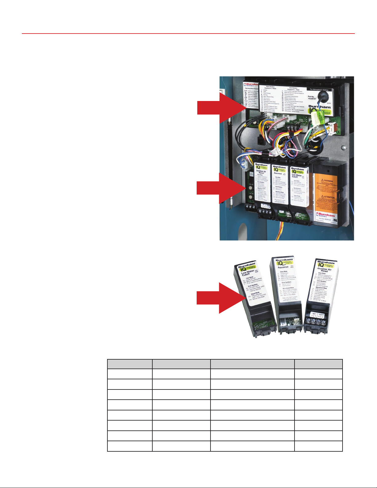
2.0 IQ Gas Boiler Control System .......................................................................................................................................... 4
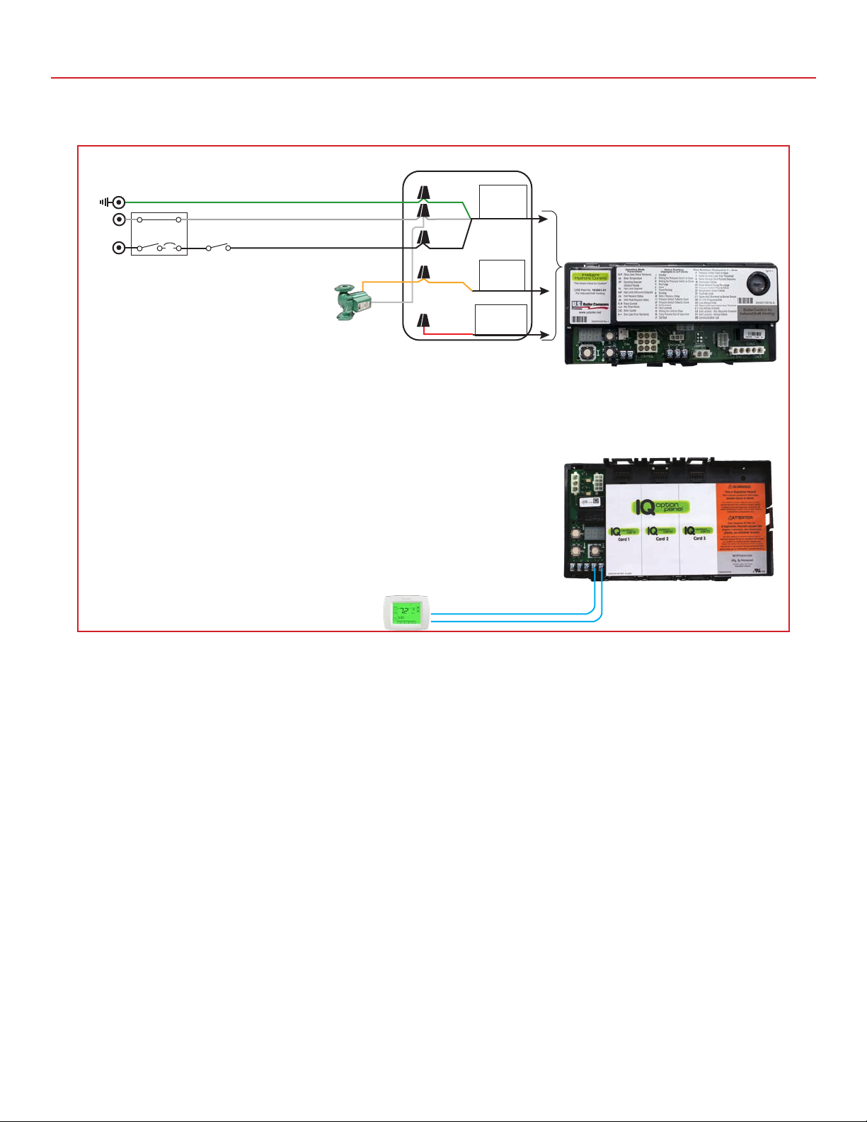
2.1 Single Zone Heating ............................................................................................................................................... 5
2.2 Single Zone Heating, Power Stealing Thermostat................................................................................................... 6
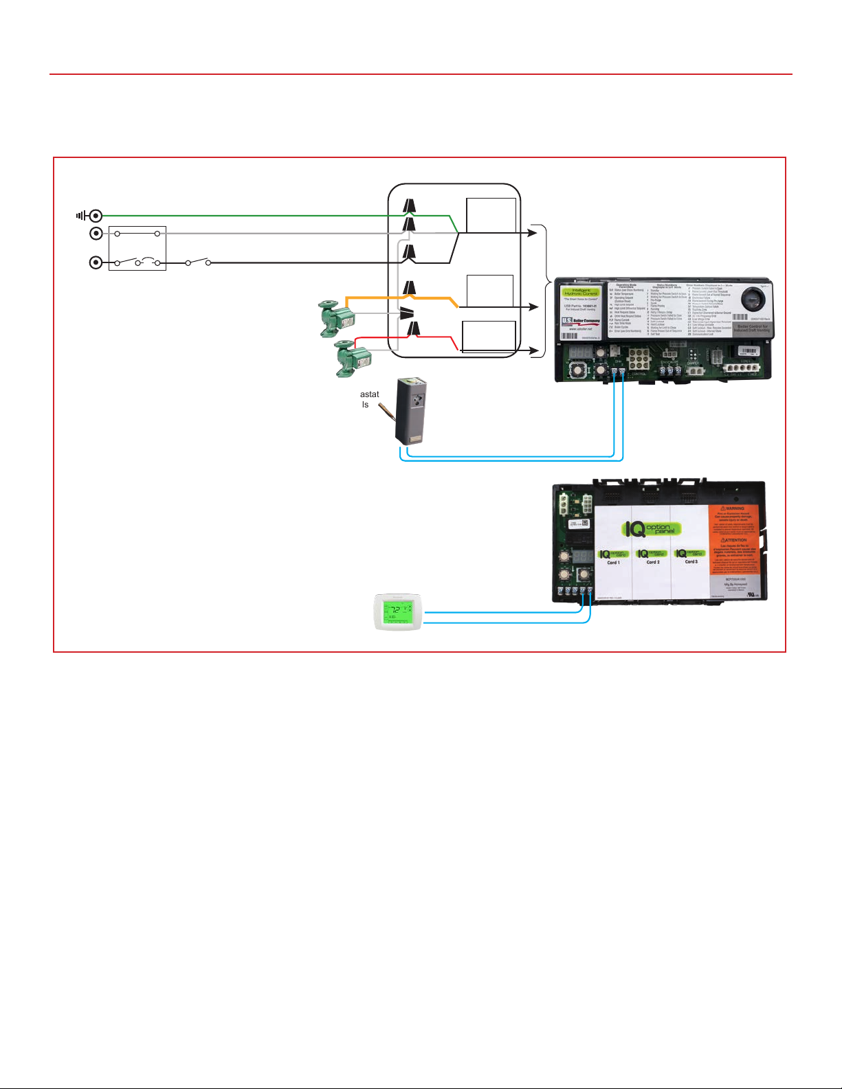
2.3 Single Zone Heating, IWH w/TPI Control................................................................................................................ 7
2.4 Single Zone Heating, IWH w/Aquastat Control ....................................................................................................... 8
2.5 Two Zone Heating .................................................................................................................................................. 9
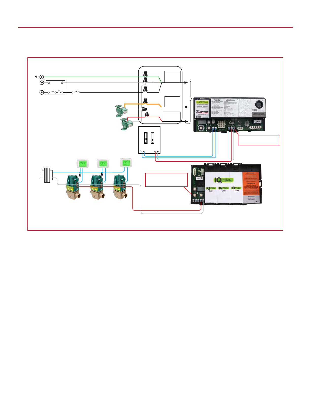
2.6 Zone Valves Heating............................................................................................................................................. 10
2.7 Zone Valves Heating, IWH w/TPI Control, 2 Circulators ....................................................................................... 11
2.8 Zone Valves Heating, IWH w/Aquastat Control, 2 Circulators............................................................................... 12
2.9 Zone Valves Heating, IWH w/TPI Control, 1 Circulators, No Priority .................................................................... 13
2.10 Zone Valves Heating, IWH w/Aquastat Control, 1 Circulators, No Priority............................................................ 14
2.11 Zone Valve Control Heating, IWH w/TPI Control, 2 Circulator .............................................................................. 15
2.12 Zone Valve Control Heating, IWH w/Aquastat Control, 2 Circulator...................................................................... 16
2.13 Zone Valve Control Heating, IWH w/TPI Control, 1 Circulator .............................................................................. 17
2.14 Zone Valve Control Heating, IWH w/Aquastat Control, 1 Circulator...................................................................... 18
2.15 Zone Switching Relay Heating.............................................................................................................................. 19
2.16 Zone Switching Relay Heating, IWH w/TPI Control .............................................................................................. 20
2.17 Zone Switching Relay Heating, IWH w/Aquastat Control...................................................................................... 21
3.0 IQ Gas Boiler Control System, Outdoor Reset Card.................................................................................................22-24
3.1 Single Zone Heating ............................................................................................................................................. 25
3.2 Single Zone Heating, IWH w/TPI Control.............................................................................................................. 26
3.3 Single Zone Heating, IWH w/Aquastat Control ..................................................................................................... 27
3.4 Zone Valves Heating, IWH w/TPI Control, 2 Circulators ....................................................................................... 28
3.5 Zone Valves Heating, IWH w/Aquastat Control, 2 Circulators............................................................................... 29
3.6 Zone Valves Heating, IWH w/TPI Control, 1 Circulators, No Priority .................................................................... 30
3.7 Zone Valves Heating, IWH w/Aquastat Control, 1 Circulators, No Priority............................................................ 31
3.8 Zone Valve Control Heating, IWH w/TPI Control, 2 Circulator .............................................................................. 32
3.9 Zone Valve Control Heating, IWH w/Aquastat Control, 2 Circulator...................................................................... 33
3.10 Zone Valve Control Heating, IWH w/TPI Control, 1 Circulator .............................................................................. 34
3.11 Zone Valve Control Heating, IWH w/Aquastat Control, 1 Circulator ..................................................................... 35
3.12 Zone Switching Relay Heating, IWH w/TPI Control .............................................................................................. 36
3.13 Zone Switching Relay Heating, IWH w/Aquastat Control...................................................................................... 37
4.0 Intelligent Hydronic Control (IHC) Series 2 & PVG Boilers Only
4.1 Single Zone Heating ............................................................................................................................................. 38
4.2 Single Zone Heating, Power Stealing Thermostat................................................................................................. 38
4.3 Single Zone Heating, Indirect Water Heater (IWH) w/TPI Control......................................................................... 39
4.4 Single Zone Heating, IWH w/Aquastat Control ..................................................................................................... 40
4.5 Two Zones Heating............................................................................................................................................... 41
4.6 Zone Valves Heating............................................................................................................................................. 42
4.7 Zone Valves Heating, IWH w/TPI Control, 2 Circulators ....................................................................................... 43
4.8 Zone Valves Heating, IWH w/Aquastat Control, 2 Circulators............................................................................... 44
4.9 Zone Valves Heating, IWH w/TPI Control, 1 Circulators, No Priority .................................................................... 45
4.10 Zone Valves Heating, IWH w/Aquastat Control, 1 Circulators, No Priority............................................................ 46
4.11 Zone Valve Control Heating, IWH w/TPI Control, 2 Circulator .............................................................................. 47
4.12 Zone Valve Control Heating, IWH w/Aquastat Control, 2 Circulator...................................................................... 48
4.13 Zone Valve Control Heating, IWH w/TPI Control, 1 Circulator .............................................................................. 49
4.14 Zone Valve Control Heating, IWH w/Aquastat Control, 1 Circulator...................................................................... 50
4.15 Zone Switching Relay Heating.............................................................................................................................. 51
4.16 Zone Switching Relay Heating, IWH w/TPI Control .............................................................................................. 52
4.17 Zone Switching Relay Heating, IWH w/Aquastat Control...................................................................................... 53

Gas Boiler Wiring & Application Guide
U.S. Boiler Company
08/23/13
3
1.0 Introduction
Intelligent Hydronic Control and IQ Control Systems included on various Burnham Brand boilers contain features and capabilities, which
can improve heating system operation, reduce fuel costs, improve comfort, and efficiency. By including unique capabilities, Burnham
brand boilers can do more, with less field wiring, and fewer aftermarket controls and components – improving the operation of both new
and replacement boiler installations.
These application drawings include detailed wiring diagrams, and set-up details, allowing installers to fully utilize the capability and
versatility of the control systems. These applications can save installers time and money on just about any heating system – whether it’s
a new installation, or replacing an older, less efficient boiler.
Notice:
While this manual contains wiring diagrams and set-up details, the Installation Operating and Service Instruction’s provided with
each Burnham brand boiler must be followed.
Notice:
Install wiring and electrically ground boiler in accordance with requirements of the authority having jurisdiction, or in absence of
such requirements the National Electrical Code, ANSI/NFPA 70, and/or the CSA C22.1 Electric Code.
Using this Guide
Line Voltage Abbreviations
L1 – 120Vac Hot – Black IHC Intelligent Hydronic Control
L2 – 120Vac Neutral - White OCP IQ Option Panel
Ground - Green TPI Alliance IWH control
IQ (Gas Boiler System) Combination of IHC and OCP on the boiler
“T-T” Thermostat connection terminals
Low Voltage
Polarity Important
Red 24 Vac Hot
White (Grey) 24Vac Ground
Polarity Not Important
Blue wires

Gas Boiler Wiring & Application Guide
U.S. Boiler Company
08/23/13
4
2.0 IQ Gas Boiler Control System
The Burnham ES2, ESC & Series 3 boilers feature Burnham’s IQ gas Boiler Control system, which greatly simplifies installation and
set-up in both existing and new heating systems. The IQ Control system contains many unique features and capabilities that save the
installer time and take the mystery out of controls by providing simple, clear information about settings, status, and diagnostics on an
LED display on the boiler. The IQ gas Boiler Control System consists of the following components:
Intelligent Hydronic Gas Boiler Control features an integrated
boiler temperature sensor, and ignition control into one for seamless
operation. The Intelligent Hydronic Control features an LED read-out,
which displays operating information such as boiler status and boiler
water temperature. The Intelligent Hydronic Control also displays
diagnostic info such as run time hours, the number of heating cycles,
flame signal strength, and error codes for improved diagnostics
The IQ Option Panel is a separate control panel that accepts IQ
Option Cards for added efficiency and safety. IQ Option Cards snap
into any one of the three Slots in the Option Panel, and are instantly
recognized when the IQ System is powered up. A separate LED
display provides setting, status, & diagnostic info for each of the
IQ Option Cards, greatly simplifying the set-up and operation of the
control. IQ Option Cards are cost effective, they save time, and they
are functionally superior to stand alone Limits, LWCO’s and Outdoor
Reset controls. Not available with the Series 2 Boiler.
IQ Option Cards are snap-in control modules which attach to the
Option Panel, and contain various control upgrades, such as Auxiliary
High Temperature Limit, Low Water Cut-Off protection, and Outdoor
Air Reset. There’s an IQ Option Card for each feature. Option Cards
simply plug into the Option Panel, and feature a one or two wire
connection to a sensor. Not available with the Series 2 boiler.
Parameter Range Parameter Description Default
HL 140°F – 220°F High Limit Setting 180°F
dF 10°F – 30°F High Limit Differential 15°F
Or 0 – 20 Minutes Circulator Overrun Time 0 Minutes
PP 2 –20 Minutes Circulator Pre-purge Time 2 Minutes
St 140°F –180°F Start Temperature 140°F
Pt On – Off Priority Time (DHW) On
dh Dh or TT2 DH Terminal Function dh
F-C F or C Degrees F or C F
Intelligent Hydronic Control Adjustment Mode Options
The Intelligent Hydronic
Control’s (IHC) “Dh”
parameter provides the ability
to control the two separate
heating demands or a heating
demand and an Indirect Water
Heater (IWH) demand without
the use of additional controls.

Gas Boiler Wiring & Application Guide
U.S. Boiler Company
08/23/13
5
2.0 IQ Gas Boiler Control System
120V AC
Power
Supply
System
Circulator
DHW/Zone
Circulator
Boiler Junction Box
Line Voltage Wiring Connections
Green
White
Black
Yellow
System
Circulator
Service Switch
(Optional)
Overcurrent
Protection/
Disconnect
GND
L2
L1
Power
Supply
120/60/1
Thermostat 1
1 2 3 T T
1 2 1 2 3
Red
Explanation:
This arrangement can be used when an IQ gas boiler is connected to a single zone heating system.
• AthermostatwiredtotheOCP“TT”terminalsprovideaheatingdemandandenergizestheyellowsystemwire.
2.1 Single Zone Heating

Gas Boiler Wiring & Application Guide
U.S. Boiler Company
08/23/13
6
2.0 IQ Gas Boiler Control System
Explanation:
This arrangement can be used with a single zone heating system with a power stealing thermostat
• AthermostatwiredtotheOCP“TT”terminalsprovideaheatingdemandandenergizestheyellowsystemcirculatorwire.
2.2 Single Heat Zone, Power Stealing Thermostat
120V AC
Power
Supply
System
Circulator
DHW/Zone
Circulator
Boiler Junction Box
Line Voltage Wiring Connections
Green
White
Black
Yellow
System
Circulator
Service Switch
(Optional)
Overcurrent
Protection/
Disconnect
GND
L2
L1
Power
Supply
120/60/1
Thermostat 1
1 2 3 T T
1 2 1 2 3
Red
Terminal 2 is 24V AC positive
Terminal 3 is 24V AC ground
Left T is 24V AC positive

Gas Boiler Wiring & Application Guide
U.S. Boiler Company
08/23/13
7
2.0 IQ Gas Boiler Control System
Explanation:
This arrangement can be used with a single heat zone and DHW demand from the TPI control.
• AthermostatwiredtotheOCP“TT”terminalsprovideaheatingdemandandenergizestheyellowsystemcirculatorwire.
The TPI control wired to the IHC “1” & “2” terminals provides a DHW demand and energizes the red DHW/Zone circulator
wire.
• TheIHCparmater“dh” must be set to “dh” and when the “Pt” Priority Time parameter is set to “on”, it will prioritize the
IWH without at time out period.
• CAUTION: Proper polarity must be maintained on the red and white wires to avoid possible damage to the OCP and TPI
controls.
2.3 Single Heat Zone Heating, IWH w/TPI Control
120V AC
Power
Supply
System
Circulator
DHW/Zone
Circulator
Boiler Junction Box
Line Voltage Wiring Connections
Green
White
Black
Yellow
System
Circulator
Service Switch
(Optional)
Overcurrent
Protection/
Disconnect
GND
L2
L1
Power
Supply
120/60/1
Alliance SL
Indirect
Water Heater
TPI Control
1 2 3 T T
1 2 1 2 3
Red
DHW
Circulator
Terminal 2 is 24V AC positive
Terminal 3 is 24V AC ground
Thermostat 1
24V
pump/TT

Gas Boiler Wiring & Application Guide
U.S. Boiler Company
08/23/13
8
2.0 IQ Gas Boiler Control System
Explanation:
This arrangement can be used with a single heat zone and DHW demand from an Aquastat.
• AthermostatwiredtotheOCP“TT”terminalsprovideaheatingdemandandenergizestheyellowsystemcirculatorwire.
The TPI control wired to the IHC “1” & “2” terminals provides a DHW demand and energizes the red DHW/Zone circulator
wire.
• TheIHCparmater“dh” must be set to “dh” and when the “Pt” Priority Time parameter is set to “on”, it will prioritize the
IWH without at time out period.
2.4 Single Heat Zone Heating, IWH w/Aquastat Control
120V AC
Power
Supply
System
Circulator
DHW/Zone
Circulator
Boiler Junction Box
Line Voltage Wiring Connections
Green
White
Black
Yellow
System
Circulator
Service Switch
(Optional)
Overcurrent
Protection/
Disconnect
GND
L2
L1
Power
Supply
120/60/1
Thermostat 1
IWH Aquastat
Controls
1 2 3 T T
1 2 1 2 3
Red
DHW
Circulator

Gas Boiler Wiring & Application Guide
U.S. Boiler Company
08/23/13
9
2.0 IQ Gas Boiler Control System
Explanation:
This arrangement allows the boiler to respond to two heating demands through the IHC control and operate both circulators
without priority.
• AZone-1thermostatwiredtotheOCP“TT”TerminalsprovidesaZone-1heatingdemandandenergizestheyellowsystem
circulator wire. A Zone-2 thermostat wired to the IHC “1” and “2” terminals provides a Zone-2 demand and energizes the red
DHW/Zone circulator wire.
• TheIHCparameter“dh” must be set to “tt2” and the “Pt” Priority Time parameter is ignored so both circulators can run
simultaneously.
2.5 Two Zone Heating
120V AC
Power
Supply
System
Circulator
DHW/Zone
Circulator
Boiler Junction Box
Line Voltage Wiring Connections
Green
White
Black
Yellow
Zone 1
Circulator
Service Switch
(Optional)
Overcurrent
Protection/
Disconnect
GND
L2
L1
Power
Supply
120/60/1
Thermostat 1
1 2 3 T T
1 2 1 2 3
Red
Zone 2
Circulator
Thermostat 2

Gas Boiler Wiring & Application Guide
U.S. Boiler Company
08/23/13
10
2.0 IQ Gas Boiler Control System
Explanation:
This arrangement allows the boiler to respond to a space heating demand utilizing Taco 3-wire zone valves.
• ThezonevalveendswitcheswiredtotheOCP“TT”Terminals,provideaheatingdemand,andenergizetheyellowsystem
circulator wire.
• CAUTION: Proper polarity must be maintained on the red and white wires to avoid possible damage to the OCP.
2.6 Zone Valve Heating
120V AC
Power
Supply
System
Circulator
DHW/Zone
Circulator
Boiler Junction Box
Line Voltage Wiring Connections
Green
White
Black
Yellow
System
Circulator
Service Switch
(Optional)
Overcurrent
Protection/
Disconnect
GND
L2
L1
Power
Supply
120/60/1
Thermostat 3
1 2 3 T T
1 2 1 2 3
Red
DHW
Circulator
Terminal 2 is 24V AC positive
Terminal 3 is 24V AC ground
Left “T” is 24V AC positive
Thermostat 2
Thermostat 1
24V AC Positive
40VA
Transformer
Field Installed
Power
Supply
120/60/1
L1
L2
NOTE
Zone Valve Terminal 2 must be
connected to 24V AC
Common failure to do so will result in
damaged equipment

Gas Boiler Wiring & Application Guide
U.S. Boiler Company
08/23/13
11
2.0 IQ Gas Boiler Control System
Explanation:
This arrangement allows the boiler to respond to a space heating demand utilizing Taco 3-wire zone valves and a DHW demand
from a TPI control.
• ThezonevalveendswitcheswiredtotheOCP“TT”Terminals,provideaheatingdemand,andenergizetheyellowsystem
circulator wire. The TPI Control wired to the IHC “1” & “2” terminals provide a DHW demand and energize the red DHW/
Zone circulator wire.
• TheIHCparameter“dh” must be set to “dh” and when the “Pt” Priority Time parameter is set to “on” it will prioritize the
IWH without a time out period
• CAUTION: Proper polarity must be maintained on the red and white wires to avoid possible damage to the OCP and TPI
control.
2.7 Zone Valve Heating, IWH w/TPI Control, 2 Circulators
120V AC
Power
Supply
System
Circulator
DHW/Zone
Circulator
Boiler Junction Box
Line Voltage Wiring Connections
Green
White
Black
Yellow
System
Circulator
Service Switch
(Optional)
Overcurrent
Protection/
Disconnect
GND
L2
L1
Power
Supply
120/60/1
Thermostat 3
1 2 3 T T
1 2 1 2 3
Red
DHW
Circulator
Terminal 2 is 24V AC positive
Terminal 3 is 24V AC ground
Left “T” is 24V AC positive
Thermostat 2
Thermostat 1
24V AC Positive
40VA
Transformer
Field Installed
Power
Supply
120/60/1
L1
L2
NOTE
Zone Valve Terminal 2 must be
connected to 24V AC
Common failure to do so will result in
damaged equipment
Alliance SL
Indirect
Water Heater
TPI Control
Terminal 2 is 24V AC positive
Terminal 3 is 24V AC ground
24V
pump/TT

Gas Boiler Wiring & Application Guide
U.S. Boiler Company
08/23/13
12
2.0 IQ Gas Boiler Control System
Explanation:
This arrangement allows the boiler to respond to a space heating demand utilizing Taco 3-wire zone valves and a DHW demand
from an Aquastat control.
• ThezonevalveendswitcheswiredtotheOCP“TT”Terminals,provideaheatingdemand,andenergizetheyellowsystem
circulator wire. The IWH Aquastat Control wired to the IHC “1” & “2” terminals provide a DHW demand and energize the red
DHW/Zone circulator wire.
• TheIHCparameter“dh” must be set to “dh” and when the “Pt” Priority Time parameter is set to “on” it will prioritize the
IWH without a time out period
• CAUTION: Proper polarity must be maintained on the red and white wires to avoid possible damage to the OCP.
2.8 Zone Valve Heating, IWH w/Aquastat Control, 2 Circulators
120V AC
Power
Supply
System
Circulator
DHW/Zone
Circulator
Boiler Junction Box
Line Voltage Wiring Connections
Green
White
Black
Yellow
System
Circulator
Service Switch
(Optional)
Overcurrent
Protection/
Disconnect
GND
L2
L1
Power
Supply
120/60/1
Thermostat 3
1 2 3 T T
1 2 1 2 3
Red
DHW
Circulator
Terminal 2 is 24V AC positive
Terminal 3 is 24V AC ground
Left “T” is 24V AC positive
Thermostat 2
Thermostat 1
24V AC Positive
40VA
Transformer
Field Installed
Power
Supply
120/60/1
L1
L2
NOTE
Zone Valve Terminal 2 must be
connected to 24V AC
Common failure to do so will result in
damaged equipment
IWH Aquastat
Control

Gas Boiler Wiring & Application Guide
U.S. Boiler Company
08/23/13
13
2.0 IQ Gas Boiler Control System
Explanation:
This arrangement allows the use of zone valves for heat and hot water using a single circulator without DHW priority.
• TheheatingzonevalveendswitcheswiredtotheOCP“TT”Terminals,provideaheatingdemand,andenergizetheyellow
system circulator wire. The TPI Control connected zone valve end switch wired to the IHC “1” & “2” terminals provide a
DHW demand and energizes the red DHW/Zone circulator wire.
• TheIHCparameter“dh” must be set to “dh”. There is no priority in this application due to using only one circulator
• WiringtheDHWzonevalveendswitchtotheIHCwillavoidtheboilertemperaturedelayedstartusedonheatdemand
• CAUTION: Proper polarity must be maintained on the red and white wires to avoid possible damage to the OCP and TPI
control.
2.9 Zone Valve Heating, IWH w/TPI Control, 1 Circulator, No Priority
120V AC
Power
Supply
System
Circulator
DHW/Zone
Circulator
Boiler Junction Box
Line Voltage Wiring Connections
Green
White
Black
Yellow
System
Circulator
Service Switch
(Optional)
Overcurrent
Protection/
Disconnect
GND
L2
L1
Power
Supply
120/60/1
1 2 3 T T
1 2 1 2 3
Red
Thermostat 2
Thermostat 1
24V AC Positive
40VA
Transformer
Field Installed
Power
Supply
120/60/1
L1
L2
NOTE
Zone Valve Terminal 2 must be
connected to 24V AC
Common failure to do so will result in
damaged equipment
Alliance SL
Indirect
Water Heater
TPI Control
Caution: When using a zone valve on an
IWH, we strongly suggest the use of a
mixing valve installed on the domestic
water side of the indirect water heater
System
Circulator
With this application, there will
not be DHW priority
Terminal 2 is 24V AC positive
Terminal 3 is 24V AC ground
Left “T” is 24V AC positive
Terminal 2 is 24V AC positive
Terminal 3 is 24V AC ground
24V
pump/TT

Gas Boiler Wiring & Application Guide
U.S. Boiler Company
08/23/13
14
2.0 IQ Gas Boiler Control System
Explanation:
This arrangement allows the use of zone valves for heat and hot water using a single circulator without DHW priority.
• TheheatingzonevalveendswitcheswiredtotheOCP“TT”Terminals,provideaheatingdemand,andenergizestheyellow
system circulator wire. The IWH Aquastat Control connected zone valve end switch wired to the IHC “1” & “2” terminals
provide a DHW demand and energizes the red DHW/Zone circulator wire.
• TheIHCparameter“dh” must be set to “dh”. There is no priority in this application due to using only one circulator.
• WiringtheDHWzonevalveendswitchtotheIHCwillavoidtheboilertemperaturedelayedstartusedonheatdemand.
• CAUTION: Proper polarity must be maintained on the red and white wires to avoid possible damage to the OCP and IHC.
2.10 Zone Valve Heating, IWH w/TPI Control, 1 Circulator, No Priority
120V AC
Power
Supply
System
Circulator
DHW/Zone
Circulator
Boiler Junction Box
Line Voltage Wiring Connections
Green
White
Black
Yellow
System
Circulator
Service Switch
(Optional)
Overcurrent
Protection/
Disconnect
GND
L2
L1
Power
Supply
120/60/1
1 2 3 T T
1 2 1 2 3
Red
Terminal 2 is 24V AC positive
Terminal 3 is 24V AC ground
Left “T” is 24V AC positive
Thermostat 2
Thermostat 1
24V AC Positive
40VA
Transformer
Field Installed
Power
Supply
120/60/1
L1
L2
NOTE
Zone Valve Terminal 2 must be
connected to 24V AC
Common failure to do so will result in
damaged equipment
IWH Aquastat
Control
Caution: When using a zone valve on an
IWH, we strongly suggest the use of a
mixing valve installed on the domestic
water side of the indirect water heater
With this application, there will
not be DHW priority

Gas Boiler Wiring & Application Guide
U.S. Boiler Company
08/23/13
15
2.0 IQ Gas Boiler Control System
Explanation:
This application uses a zone valve control for heating demands and the DHW demand using at TPI control
• ThezonecontrolendswitchwiredtotheOCP“TT”Terminals,provideaheatingdemand,andenergizestheyellowsystem
circulator wire. The TPI Control wired to the IHC “1” & “2” terminals provide a DHW demand and energizes the red DHW/
Zone circulator wire.
• TheIHCparameter“dh” must be set to “dh”, and when the “Pt” Priority Time parameter is set to “on”, it will prioritize the
IWH without a time out period.
• CAUTION: Proper polarity must be maintained on the red and white wires to avoid possible damage to the OCP and TPI
Control.
2.11 Zone Valve Heating, IWH w/TPI Control, 2 Circulators
Thermostat 1 Thermostat 2
X X R W C R W C R W C
ZONE 1 ZONE 2 ZONE 3
THERMOSTATS (24V AC) PRIORITY
ISOLATED
END SWITCH
ZVC 403-4
THREE ZONE
ZONE VALVE CONTROL
ZONE 1 ZONE 2 ZONE 3
PRIORITY
24V AC ZONE VALVES
1 2 3 4 1 2 3 41 2 3 4
ZONE 3
PRIORITY
ON
OFF LED
INDICATORS
POWER
T STAT 1
T STAT 2
T STAT 3
VALVE 1
VALVE 2
VALVE 3
FUSE
5 AMP
POWER IN
ZONE 3 PUMP
END SWITCH
PUMP END
SWITCH
N/O COM N/C
X X
1 2 3 T T
1 2 1 2 3
120V AC
Power
Supply
System
Circulator
DHW/Zone
Circulator
Boiler Junction Box
Line Voltage Wiring Connections
Green
White
Black
Yellow
System
Circulator
Service Switch
(Optional)
Overcurrent
Protection/
Disconnect
GND
L2
L1
Power
Supply
120/60/1
Red
DHW
Circulator
Alliance SL
Indirect
Water Heater
TPI Control
Thermostat 3
Terminal 2 is 24V AC positive
Terminal 3 is 24V AC ground
24V
pump/TT

Gas Boiler Wiring & Application Guide
U.S. Boiler Company
08/23/13
16
2.0 IQ Gas Boiler Control System
Explanation:
This application uses a zone valve control for heating demands and the DHW demand using an Aquastat control
• ThezonecontrolendswitchwiredtotheOCP“TT”Terminals,provideaheatingdemand,andenergizestheyellowsystem
circulator wire. The IWH Aquastat Control wired to the IHC “1” & “2” terminals provide a DHW demand and energizes the
red DHW/Zone circulator wire.
• TheIHCparameter“dh” must be set to “dh”, and when the “Pt” Priority Time parameter is set to “on”, it will prioritize the
IWH without a time out period.
• CAUTION: Proper polarity must be maintained on the red and white wires to avoid possible damage to the OCP.
2.12 Zone Valve Control Heating, IWH w/Aquastat Control, 2 Circulators
Thermostat 1 Thermostat 2
X X R W C R W C R W C
ZONE 1 ZONE 2 ZONE 3
THERMOSTATS (24V AC) PRIORITY
ISOLATED
END SWITCH
ZVC 403-4
THREE ZONE
ZONE VALVE CONTROL
ZONE 1 ZONE 2 ZONE 3
PRIORITY
24V AC ZONE VALVES
1 2 3 4 1 2 3 41 2 3 4
ZONE 3
PRIORITY
ON
OFF LED
INDICATORS
POWER
T STAT 1
T STAT 2
T STAT 3
VALVE 1
VALVE 2
VALVE 3
FUSE
5 AMP
POWER IN
ZONE 3 PUMP
END SWITCH
PUMP END
SWITCH
N/O COM N/C
X X
1 2 3 T T
1 2 1 2 3
120V AC
Power
Supply
System
Circulator
DHW/Zone
Circulator
Boiler Junction Box
Line Voltage Wiring Connections
Green
White
Black
Yellow
System
Circulator
Service Switch
(Optional)
Overcurrent
Protection/
Disconnect
GND
L2
L1
Power
Supply
120/60/1
Red
DHW
Circulator
Thermostat 3 IWH Aquastat
Control
Terminal 2 is 24V AC positive
Terminal 3 is 24V AC ground
Left “T” is 24V AC positive

Gas Boiler Wiring & Application Guide
U.S. Boiler Company
08/23/13
17
2.0 IQ Gas Boiler Control System
Explanation:
This application uses a zone valve control for heating demands and the DHW demand wired directly to the IHC control utilizing
one circulator. Priority is controlled by the zone valve relay control.
• ThezonecontrolendswitchwiredtotheOCP“TT”Terminals,provideaheatingdemand,andenergizestheyellowsystem
circulator wire. The Zone 3 Pump end switch wired to the IHC “1” & “2” terminals provide a DHW demand and energizes the
red DHW/Zone circulator wire.
• TheIHCparameter“dh” must be set to “dh”. There is no circulator priority in this application due to using only one
circulator.
• Wiringthezonevalvecontrol“zonepump3endswitch”toDHWterminalswillavoidtheboilertemperaturedelayedstart
used on heat demand.
• CAUTION: Proper polarity must be maintained on the red and white wires to avoid possible damage to the TPI Control.
2.13 Zone Valve Control Heating, IWH w/TPI Control, 1 Circulator
120V AC
Power
Supply
System
Circulator
DHW/Zone
Circulator
Boiler Junction Box
Line Voltage Wiring Connections
Green
White
Black
Yellow
System
Circulator
Service Switch
(Optional)
Overcurrent
Protection/
Disconnect
GND
L2
L1
Power
Supply
120/60/1
Caution: When using a zone valve on an
IWH, we strongly suggest the use of a
mixing valve installed on the Domestic
water side of the Indirect Water Heater
Thermostat 1 Thermostat 2
X X R W C R W C R W C
ZONE 1 ZONE 2 ZONE 3
THERMOSTATS (24V AC) PRIORITY
ISOLATED
END SWITCH
ZVC 403-4
THREE ZONE
ZONE VALVE CONTROL
ZONE 1 ZONE 2 ZONE 3
PRIORITY
24V AC ZONE VALVES
1 2 3 4 1 2 3 41 2 3 4
ZONE 3
PRIORITY
ON
OFF LED
INDICATORS
POWER
T STAT 1
T STAT 2
T STAT 3
VALVE 1
VALVE 2
VALVE 3
FUSE
5 AMP
POWER IN
ZONE 3 PUMP
END SWITCH
PUMP END
SWITCH
N/O COM N/C
X X
1 2 3 T T
1 2 1 2 3
Alliance SL
Indirect
Water Heater
TPI Control
Terminal 2 is 24V AC positive
Terminal 3 is 24V AC ground
Left “T” is 24V AC positive
24V
pump/TT

Gas Boiler Wiring & Application Guide
U.S. Boiler Company
08/23/13
18
2.0 IQ Gas Boiler Control System
Explanation:
This application uses a zone valve control for heating demands and the DHW demand wired directly to the IHC control utilizing
one circulator. Priority is controlled by the zone valve relay control.
• ThezonecontrolendswitchwiredtotheOCP“TT”Terminals,provideaheatingdemand,andenergizestheyellowsystem
circulator wire. The Zone 3 Pump end switch wired to the IHC “1” & “2” terminals provide a DHW demand and energizes the
red DHW/Zone circulator wire.
• TheIHCparameter“dh” must be set to “dh”. There is no circulator priority in this application due to using only one
circulator.
• Wiringthezonevalvecontrol“zonepump3endswitch”toDHWterminalswillavoidtheboilertemperaturedelayedstart
used on heat demand.
2.14 Zone Valve Control Heating, IWH w/Aquastat Control, 1 Circulator
120V AC
Power
Supply
System
Circulator
DHW/Zone
Circulator
Boiler Junction Box
Line Voltage Wiring Connections
Green
White
Black
YellowSystem
Circulator
Service Switch
(Optional)
Overcurrent
Protection/
Disconnect
GND
L2
L1
Power
Supply
120/60/1
Caution: When using a zone valve on an
IWH, we strongly suggest the use of a
mixing valve installed on the Domestic
water side of the Indirect Water Heater
Thermostat 1 Thermostat 2
IWH Aquastat
Control
X X R W C R W C R W C
ZONE 1 ZONE 2 ZONE 3
THERMOSTATS (24V AC) PRIORITY
ISOLATED
END SWITCH
ZVC 403-4
THREE ZONE
ZONE VALVE CONTROL
ZONE 1 ZONE 2 ZONE 3
PRIORITY
24V AC ZONE VALVES
1 2 3 4 1 2 3 41 2 3 4
ZONE 3
PRIORITY
ON
OFF LED
INDICATORS
POWER
T STAT 1
T STAT 2
T STAT 3
VALVE 1
VALVE 2
VALVE 3
FUSE
5 AMP
POWER IN
ZONE 3 PUMP
END SWITCH
PUMP END
SWITCH
N/O COM N/C
X X
1 2 3 T T
1 2 1 2 3
Terminal 2 is 24V AC positive
Terminal 3 is 24V AC ground
Left “T” is 24V AC positive

Gas Boiler Wiring & Application Guide
U.S. Boiler Company
08/23/13
19
2.0 IQ Gas Boiler Control System
Explanation:
This arrangement allows the boiler to respond to heating demands and control all the circulators from a zone switching relay.
• ThezonecontrolendswitchwiredtotheOCP“TT”Terminals,provideaheatingdemand,andenergizestheyellowsystem
circulator wire.
2.15 Zone Switching Relay Heating
120V AC
Power
Supply
System
Circulator
DHW/Zone
Circulator
Boiler Junction Box
Line Voltage Wiring Connections
Green
White
Black
Yellow
Service Switch
(Optional)
Overcurrent
Protection/
Disconnect
GND
L2
L1
Power
Supply
120/60/1
Thermostat 1 Thermostat 2
ISOLATED
END
SWITCH
SR 503-4
THREE ZONE SWITCHING RELAY
LED
INDICATORS
POWER
ZONE 1
ZONE 2
ZONE 3
FUSE
5
AMP
1 2 3 T T
1 2 1 2 3
Thermostat 3
X X R W R W R W
ZONE 1 ZONE 2 ZONE 3
PRIORITY
THERMOSTATS (24V AC)
FUSE
5
AMP
FUSE
5
AMP
FUSE
5
AMP
ZONE 3
PRIORITY
ON
OFF
24V AC
COM
INPUT
120V AC
120 VAC CIRCULATORS
120 VAC
ZC ZR ZONE 1 ZONE 2
ZONE 3
PRIORITY
HHN H N H N H N H
Red
NOTE
Supply power to Zone Switching Relay
from same discount as boiler
Terminal 2 is 24V AC positive
Terminal 3 is 24V AC ground
Left “T” is 24V AC positive

Gas Boiler Wiring & Application Guide
U.S. Boiler Company
08/23/13
20
2.0 IQ Gas Boiler Control System
Explanation:
This arrangement allows the boiler to respond to heating demands and control all the circulators from a Zone Switching Relay.
IHW takes priority through the IHC control via the yellow system pump wire.
• ThezonecontrolendswitchwiredtotheOCP“TT”Terminals,provideaheatingdemand,andenergizestheyellowsystem
circulator wire. The TPI Control wired to the IHC “1” & “2” terminals provide a DHW demand and energizes the red DHW/
Zone circulator wire.
• Aheatdemandwillenergizetheyellowwirewhichwillsupplyvoltagetothezonepumpsviathe“ZC”terminalsonthezone
relay. When the DHW demand activates, the IHC will de-energize the yellow system circulator wire and energize the red DHW
circulator. When the DHW demand expires, the IHC will de-energzie the red wire and re-energize the yellow wire, providing
there is still a call for heat
• TheIHCparameter“dh” must be set to “dh”, and when the “Pt” Priority Time parameter is set to “on”, it will prioritize the
IWH without a time out period.
• CAUTION: Proper polarity must be maintained on the red and white wires to avoid possible damage to the OCP and TPI
Control.
2.16 Zone Switching Relay Heating, IWH w/TPI Control
120V AC
Power
Supply
System
Circulator
DHW/Zone
Circulator
Boiler Junction Box
Line Voltage Wiring Connections
Green
White
Black
Yellow
Service Switch
(Optional)
Overcurrent
Protection/
Disconnect
GND
L2
L1
Power
Supply
120/60/1
Thermostat 1 Thermostat 2
ISOLATED
END
SWITCH
SR 503-4
THREE ZONE SWITCHING RELAY
LED
INDICATORS
POWER
ZONE 1
ZONE 2
ZONE 3
FUSE
5
AMP
1 2 3 T T
1 2 1 2 3
Thermostat 3
X X R W R W R W
ZONE 1 ZONE 2 ZONE 3
PRIORITY
THERMOSTATS (24V AC)
FUSE
5
AMP
FUSE
5
AMP
FUSE
5
AMP
ZONE 3
PRIORITY
ON
OFF
24V AC
COM
INPUT
120V AC
120 VAC CIRCULATORS
120V AC
ZC ZR ZONE 1 ZONE 2
ZONE 3
PRIORITY
HHN H N H N H N H
Red
NOTE
Supply power to Zone Switching Relay
from same discount as boiler
Alliance SL
Indirect
Water Heater
TPI Control
Terminal 2 is 24V AC positive
Terminal 3 is 24V AC ground
DHW
Circulator
Remove jumper
between ZC & ZR
Terminal 2 is 24V AC positive
Terminal 3 is 24V AC ground
Left “T” is 24V AC positive
24V
pump/TT
This manual suits for next models
3
Table of contents
Other Boiler Company Boiler manuals
Popular Boiler manuals by other brands

Triad
Triad Triumph series manual

Biasi
Biasi Activ A Plus 25C User manual and installation instructions

Rotex
Rotex A1 BG Inline Installation and maintenance instructions

Herz
Herz firestar de Luxe 18 operating instructions

Immergas
Immergas MAIOR EOLO 4 E Series Technical documentation

Radiant
Radiant RK 25 user manual

Potterton
Potterton Suprima 30L Installation & service instructions

Potterton
Potterton Promax 24 Combi ErP Installation and service manual

IDEAL
IDEAL Harrier GTE 5 Installation and servicing

Viessmann
Viessmann VD2-320 installation instructions

PB Heat
PB Heat Peerless Combi 160 user manual

Laars
Laars FT Series user manual