Boiler Company Burnham Hydronics Alpine ALP080 Service manual

101602-01-2/08 Price - $5.00
DNAGNITAREPO,NOITALLATSNI
ROFSNOITCURTSNIECIVRES
™ENIPLA
YCNEICIFFEHGIHGNISNEDNOC
TNEVTCERID
RELIOBRETAWTOHDERIF-SAG
As an ENERGY STAR®Partner, Burnham Hydronics has determined that the Alpine™ Series meets the ENERGY
STAR® guidelines for energy efciency established by the United States Environmental Protection Agency (EPA).
WARNING: Improper installation, adjustment, alteration, service or maintenance can cause property damage,
injury, or loss of life. For assistance or additional information, consult a qualied installer, service agency or the
gas supplier. This boiler requires a special venting system. Read these instructions carefully before installing.

2
IMPORTANT INFORMATION - READ CAREFULLY
NOTE: The equipment shall be installed in accordance with those installation regulations enforced in the area where the
installation is to be made. These regulations shall be carefully followed in all cases. Authorities having jurisdiction
shall be consulted before installations are made.
All wiring on boilers installed in the USA shall be made in accordance with the National Electrical Code and/or local regulations.
All wiring on boilers installed in Canada shall be made in accordance with the Canadian Electrical Code and/or local regulations.
The following terms are used throughout this manual to bring attention to the presence of hazards of various risk levels,
or to important information concerning product life.
The New York City Department of Buildings has approved the Alpine™ Series boiler: Approval No. MEA XXXXXXXX.
The City of New York requires a Licensed Master Plumber supervise the installation of this product.
The Massachusetts Board of Plumbers and Gas Fitters has approved the Alpine™ Series boiler. See the Massachusetts Board of
Plumbers and Gas Fitters website, http://license.reg.state.ma.us/pubLic/pb_pre_form.asp for the latest Approval Code or ask
your local Sales Representative.
The Commonwealth of Massachusetts requires this product to be installed by a Licensed Plumber or Gas Fitter.
REGNAD
noitautissuodrazahyltnenimminasetacidnI
,htaednitluserlliw,dediovatonfi,hcihw
ytreporplaitnatsbusroyrujnisuoires
.egamad
REGNAD
ynarosihtfoytinicivehtnisdiuqilrosropavelbammalfrehtoroenilosagesuroerotsTONOD
.ecnailpparehto
lacirtceleynahcuotTONOD-ecnailppaynaetarepootyrtTONOD,sropavsagllemsuoyfI
yletomeramorfreilppussagehtllac,yletaidemmI.gnidliubehtnienohpynaesurohctiws
tcatnoc,elbaliavanusireilppusehtfirosnoitcurtsnis'reilppussagehtwolloF.enohpdetacol
.tnemtrapederifeht
GNINRAW
noitautissuodrazahyllaitnetopasetacidnI
,htaednitluserdluoc,dediovatonfi,hcihw
ytreporplaitnatsbusroyrujnisuoires
.egamad
NOITUAC
noitautissuodrazahyllaitnetopasetacidnI
nitluseryam,dediovatonfi,hcihw
ytreporproyrujnironimroetaredom
.egamad
ECITON
nosnoitcurtsnilaicepssetacidnI
ecnanetniamro,noitarepo,noitallatsni
otdetalertontubtnatropmierahcihw
.sdrazahyrujnilanosrep

3
ECITON
.launamsihtfokcabehtnodetnirpsihcihwfoypoca,ytnarrawdetimilasahreliobsihT
dellatsniyltcerroceraslortnocllatahteesotrotcartnocgnillatsniehtfoytilibisnopserehtsitI
.etelpmocsinoitallatsniehtnehwylreporpgnitarepoeradna
GNINRAW
ehtwolloF.ylefasetarepootecivresdnaecnanetniamralugerseriuqerreliobsihT
.launamsihtnideniatnocsnoitcurtsni
ytreporpesuacnacecnanetniamroecivres,noitaretla,tnemtsujda,noitallatsnireporpmI
erofeblaunameritneehtdnatsrednudnadaeR.efilfossolroyrujnilanosrep,egamad
ebtsumecivresdnanoitallatsnI.ecivresro,noitarepopu-trats,noitallatsnignitpmetta
.ycnegaecivresrorellatsnielbaegdelwonkdna,delliks,decneirepxenaybylnodemrofrep
.detnevylreporpebtsumreliobsihT
snoisivorperaerehtosdellatsniebtsumdnanoitarepoefasrofriahserfsdeenreliobsihT
.rianoitalitnevdnanoitsubmocetauqedarof
ehtfotratsehterofebdenaelcdnadetcepsniebtsummetsysgnitnevehtforoiretniehT
ynarofnosaesgnitaehehttuohguorhtyllacidoirepdetcepsniebdluohsdnanosaesgnitaeh
suoixonwollaotyrassecensimetsysgnitnevdetcurtsbonudnanaelcA.snoitcurtsbo
drawotetubirtnoclliwdnaylefastnevotefilfossolroyrujniesuacdluoctahtsemuf
.ycneiciffes'reliobehtgniniatniam
gnippatehtotnidellatsnisievlavfeilererusserpasselnuetelpmoctonsinoitallatsnI
roflaunamsihtfonoitceSmirTdnagnipiPretaWehteeS-.ecnailppafoedistfelnodetacol
.sliated
tondnanwodtuhsotreliobehtesuacyamhcihwsecivedytefashtiwdeilppussireliobsihT
metsysgnitaeheht,ytilibissopasisepipnezorfoteudegamadfI.ecivrestuohtiwtrats-er
dluohssmraladnasdraugefasetairporpparo;rehtaewdlocnidednettanutfelebtondluohs
.evitareponisireliobehtfiegamadtneverpotmetsysgnitaehehtnodellatsnieb
sgnittifepipynawercsnutonoD.erusserphgihrednuretawtohyrevsniatnocreliobsihT
ehtgnirussaylevitisoptuohtiwreliobsihtfostnenopmocynatcennocsidottpmettaron
nehwtnempiuqednagnihtolcevitcetorpraewsyawlA.erusserponsahdnaloocsiretaw
ehtnoylertonoD.seirujnidlacstneverpotreliobsihtgnicivresropugnitrats,gnillatsni
.reliobehtfoerusserpdnaerutarepmetehtenimretedotseguagerutarepmetdnaerusserp
oD.gnitareposireliobehtnehwtohyrevemocebhcihwstnenopmocsniatnocreliobsihT
.loocerayehtsselnustnenopmocynahcuotton
,acilis,animulaniatnocleufehtdnanoitsubmocfostcudorp,noitcurtsnocfoslairetamrelioB
lufmrahrocixotrehtoro/dnasedyhedla,sedixonegortin,edixonomnobrac,slatemyvaeh
foetatsehtotnwonkerahcihwdnayrujnisuoiresrohtaedesuacnachcihwsecnatsbus
reporpesusyawlA.mrahevitcudorperrehtodnastcefedhtrib,recnacesuacotainrofilaC
.ecnailppaehtybraengnikrowrognicivresnehwtnempiuqednasrotaripser,gnihtolcytefas
.htaedroyrujnilanosrepesuacnacredroreporpehtnisnoitcurtsnillawollofoteruliaF
slaunamsrerutcafunamtnenopmocnideniatnocesohtllagnidulcni,snoitcurtsnilladaeR
rogniniatniam,gnitarepo,pugnitrats,gnillatsnierofebreliobehthtiwdedivorperahcihw
.gnicivres
elbammalfrehtodnaenilosag,slairetamelbitsubmocmorfeerfdnaraelcaerareliobpeeK
.sdiuqilrosropav
.semitllataecalpniebtsumsdraugdnaserusolcne,setalprevocllA

4
Table of Contents
I. Product Description, Specifications
and Dimensional Data....................4
II. Pre-Installation...............................8
III. Unpacking Boiler ...........................9
IV. Venting........................................... 9
V. Condensate Disposal .................... 22
VI. Water Piping and Trim .................24
VII. Gas Piping....................................35
VIII. Electrical.......................................38
IX. Boiler Stacking ............................. 43
X. System Start-up ............................ 45
XI. Operation..................................... 51
XII. Service and Maintenance..............63
XIII. Troubleshooting ........................... 67
XIV. Repair Parts..................................70
I. Product Description, Specications and Dimensional Data
Alpine™ Series boilers are condensing high efciency
gas-red direct vent hot water boilers designed for use
in forced hot water space or space heating with indirect
domestic hot water heating systems, where supply water
temperature does not exceed 210°F. These boilers have
special coil type stainless steel heat exchangers, constructed,
tested and stamped per Section IV ‘Heating Boilers’of
ASME Boiler and Pressure Vessel Code, which provide a
maximum heat transfer and simultaneous protection against
ue gas product corrosion. These boilers are not designed
for use in gravity hot water space heating systems or
systems containing signicant amount of dissolved oxygen
(swimming pool water heating, direct domestic hot water
heating, etc.).
Dimension Boiler Model
ALP080 ALP105 ALP150 ALP210 ALP285 ALP399
A - Inch
(mm) 12-9/16
(320) 14
(356) 19-11/16
(500) 23-15/16
(608) 21-13/16
(554)
28-7/8
(734)
B - Inch
(mm) 5-5/8
(142) 5-13/16
(147) 7-5/16
(185) 6-3/16
(157)
C - Inch
(mm) 7-5/16
(186) 14-1/8
(358) 13-1/16
(332)
D - Inch
(mm) 9-5/16
(237) 10-3/4
(273) 16-7/16
(417) 17-1/8
(435) 18
(456) 23-3/4
(602)
E - Inch
(mm) 5-15/16
(151) 12-1/4
(312) 15-13/16
(402)
Gas Inlet F
(FPT) 1/2” 3/4” 1”
Return G
(FPT) 1” 1-1/4” 1-1/2”
Supply H
(FPT) 1” 1-1/4” 1-1/2”
Condensate Drain J * * Factory Provided Socket End Compression Pipe Joining Clamp
for 3/4” Schedule 40 PVC Pipe
Boiler Concentric
Vent Collar K
(mm/mm) 80/125 100/150
Approx. Shipping
Weight (LBS) 137 155 182 206 256 304
Table 1: Dimensional Data (See Figures 1A & 1B)

5
Figure 1A: Alpine™ - Models ALP080 thru ALP210

6
Figure 1B: Alpine™ - Models ALP285 thru ALP399

7
Table 2A: Rating Data - Models ALP080 thru ALP399 (0 to 2000 Feet Elevation Above Sea Level)
Table 2B: Rating Data - Models ALP080 thru ALP399 (2001 to 7000 Feet Elevation Above Sea Level)
Alpine Series Gas-Fired Boilers
Model
Number *
Input
(MBH) ** Output
(MBH)
Net I=B=R
Ratings
Water (MBH)
AFUE
%
Thermal
Efciency
(%)
Combustion
Efciency (%)
Boiler Water
Volume
(Gal.)
Heat Transfer
Area (Sq. Ft.)
Min. Max.
ALP080 27 80 73 63 95.0 0.6 7.3
ALP105 35 105 96 83 95.0 0.7 9.1
ALP150 50 150 137 119 95.0 1.3 16.4
ALP210 70 210 193 168 95.0 1.7 21.8
ALP285 57 285 263 229 95.0 2.4 29.1
ALP399 80 399 377 328 94.1 94.5 3.4 41.8
*Add Sufx “N” for Natural Gas or Sufx “P” for LP Gas Models.
Notes: ** DOE Heating Capacity (ALP080 thru ALP285); Gross Output (ALP399)
Maximum Working Pressure, Water - 30 PSI Shipped from Factory (std.); 50 PSI - Optional
Maximum Allowable Temperature, Water - 210°F
Boilers are factory shipped as Natural Gas builds and have to be eld adjusted for LP gas application. Refer to ‘System Start-
Up Section of this manual for detailed procedure.
For elevations above 2000 Feet, ratings should be reduced at the rate of four percent (4%) for each 1000 Feet above sea level.
Alpine Series Gas-Fired Boilers
* Model
Number
Input
(MBH) ** Output
(MBH)
Net I=B=R
Ratings
Water (MBH)
AFUE
%
Thermal
Efciency
(%)
Combustion
Efciency (%)
Boiler Water
Volume
(Gal.)
Heat Transfer
Area
(Sq. Ft.)
Min. Max.
ALP080 16 80 73 63 95.0 0.6 7.3
ALP105 21 105 96 83 95.0 0.7 9.1
ALP150 30 150 137 119 95.0 1.3 16.4
ALP210 42 210 193 168 95.0 1.7 21.8
ALP285 57 285 263 229 95.0 2.4 29.1
ALP399 80 399 377 328 94.1 94.5 3.4 41.8
*Add Sufx “N” for Natural Gas or Sufx “P” for LP Gas Models.
Notes: ** DOE Heating Capacity (ALP080 thru ALP285); Gross Output (ALP399)
Maximum Working Pressure, Water - 30 PSI Shipped from Factory (std.); 50 PSI - Optional (ALP080 thru ALP285)
Maximum Working Pressure, Water - 50 PSI Shipped from Factory (std.); (ALP399)
Maximum Allowable Temperature, Water - 210°F
Boilers are factory shipped as Natural Gas builds and have to be eld adjusted for LP gas application. Refer to ‘System Start-
Up Section of this manual for detailed procedure.
Ratings shown are for installations at sea level and elevations up to 2000 Feet. For elevations above 2000 Feet, ratings should be
reduced at the rate of four percent (4%) for each 1000 Feet above sea level.

8
GNINRAW
snoitcurtsniesehtwolloftonoduoyfI
tluseryamnoisolpxeroerifa,yltcaxe
lanosreproegamadytreporpgnisuac
.yrujni
REGNAD
rehtoroenilosagerehwreliobllatsnitonoD
fosecruosro,sdiuqilrosropavelbammalf
,srenaelc,sehcaelb.e.i(snobracordyh
cirbaf,srevomertniap,syarps,slacimehc
.derotsrodesuera).cte,srenetfos
ECITON
,reliobehtfotnetnocretawwolehtoteuD
ehtotdragerhtiwreliobehtfognizis-sim
evissecxenitluserlliwdaolmetsysgnitaeh
tnenopmocdetareleccadnagnilcycreliob
tnarrawTONSEODmahnruB.eruliaf
reliobdezis-simybdesuacseruliaf
otreliobehtezisrevoTONOD.snoitacilppa
snoitallatsnireliobraludoM.metsyseht
reliobfodoohilekilehtecuderyltaerg
.gnizisrevo
A.Installation must conform to the requirements of the
authority having jurisdiction. In the absence of such
requirements, installation must conform to the National
Fuel Gas Code, NFPA 54/ANSI Z223.1, and/or CAN/
CSA B149.1 Installation Codes.
B. Appliance is design certied for installation on
combustible ooring. Do not install boiler on
carpeting.
C. Provide clearance between boiler jacket and
combustible material in accordance with local re
ordinance. Refer to Figure 2B for minimum listed
clearances from combustible material. Recommended
service clearance is 24 inches from left side, front, top
and rear of the boiler. Recommended front clearance
may be reduced to the combustible material clearance
providing:
1. Access to boiler front is provided through a door or
removable front access panel.
II. Pre-Installation
2. Access is provided to the condensate trap located
underneath the heat exchanger.
D. Install on level oor. For basement installation provide
a solid base such as concrete, if oor is not level or if
water may be encountered on oor around boiler. Floor
must be able to support weight of boiler, water and all
additional system components.
E. Protect gas ignition system components from water
(dripping, spraying, rain, etc.) during boiler operation
and service (circulator replacement, condensate trap,
control replacement, etc.).
F. Provide combustion and ventilation air in accordance
with applicable provisions of local building codes,
or: USA - National Fuel Gas Code, NFPA 54/ANSI
Z223.1, Air for Combustion and Ventilation;
Canada - Natural Gas and Propane Installation Code,
CAN/CSA-B149.1, Venting Systems and Air Supply for
Appliances.
GNINRAW
rianoitalitnevdnanoitsubmocetauqedA
reporperussaotdedivorpebtsum
.noitsubmoc
G. The boiler should be located so as to minimize the
length of the vent system. The concentric venting,
containing integral combustion air inlet piping, must
terminate where outdoor air is available for combustion
and away from areas that may contaminate combustion
air. In particular, avoid areas near chemical products
containing chlorines, chloro/uorocarbons, paint
removers, cleaning solvents and detergents. Avoid
areas containing saw dust, loose insulation bers, dry
wall dust etc.
NOITUAC
tnemnorivnenanireliobsihtgnitarepodiovA
yrd,srebifnoitalusniesool,tsudwaserehw
sireliobfI.tneserpera.cte,tsudllaw
renrubeht,snoitidnocesehtrednudetarepo
dnadenaelcebtsumstropdnaroiretni
.noitareporeporperusniotyliaddetcepsni

9
III. Unpacking Boiler
NOITUAC
.reliobpordtonoD
A. Move boiler to approximate installed position.
B. Remove all crate fasteners.
C. Lift and remove outside container.
D. Remove boiler from cardboard positioning sleeve on
shipping skid.
GNINRAW
ebdluohsreliobsihtfonoitallatsnI
delliksdnadeniartybylnonekatrednu
.ycnegaecivresdeifilauqamorflennosrep
E. Move boiler to its permanent location.
IV. Venting
GNINRAW
fostcudorpesuacdluocsnoitcurtsniesehthtiwecnadroccanireliobsihttnevoteruliaF
royrujnilanosrep,egamadytreporperevesnignitlusergnidliubehtretneotnoitsubmoc
.htaed
neebsahohwlaudividnina(rellatsnideifilauqaybdellatsniebtsummetsysgnitnevsihT
.rellatsnidesnecilaro)deniartylreporp
gnitnevleetssselniatsroleetsdezinavlaggnisureliobsihttnevottpmettatonoD
.launamsihtfo3elbaTnidetsiltonmetsystnevrehtoynarocillatem-non,stnenopmoc
.reliobsihthtiwrepmadtnevrodoohtfard,repmadcirtemorabaesutonoD
dnaerutsioM.dniwgniliaverpotdesopxeerehwnoitanimrettnevcirtnecnocetacoltonoD
tsumecafrus,noitaroiretedtneverpoT.noitanimrettnevdnuorasecafrusnomrofyameci
.).ctedetniap,delaes(riaperdoognieb
muelortep,)s'CFC(snobracoroulf/orolhc,senirolhcerehwnoitanimrettnevetacoltonoD
reliobereveS.tneserperaslacimehcrehtorosropavelitalov,stnegreted,setallitsid
.tluserlliweruliafdnanoisorroc
.kcedarednunoitanimrettnevetacoltonoD
A. Vent Guidelines Due to Removal of an Existing
Boiler
For installations not involving the replacement of an
existing boiler, proceed to Step B.
When an existing boiler is removed from a common
venting system, the common venting system is likely
to be too large for proper venting of the remaining
appliances. At the time of removal of an existing
boiler, the following steps shall be followed with each
appliance remaining connected to the common venting
system placed in operation, while the other appliances
remaining connected to the common venting system are
not in operation:
1. Seal any unused openings in the common venting
system.
2. Visually inspect the venting system for proper
size and horizontal pitch and determine there is no
blockage or restriction, leakage, corrosion, and other
deciencies which could cause an unsafe condition.
3. Insofar as is practical, close all building doors and
windows and all doors between the space in which
the appliances remaining connected to the common
venting system are located and other spaces of the
building. Turn on clothes dryers and any appliance
not connected to the common venting system.
Turn on any exhaust fans, such as range-hoods and
bathroom exhausts, so they will operate at maximum
speed. Do not operate a summer exhaust fan. Close
replace dampers.

10
4. Place in operation the appliance being inspected.
Follow the Lighting (or Operating) Instructions.
Adjust thermostat so appliance will operate
continuously.
5. Test for spillage at the draft hood relief opening
after ve (5) minutes of main burner operation. Use
the ame of a match or candle, or smoke from a
cigarette, cigar or pipe.
6. After it has been determined that each appliance
remaining connected to the common venting system
properly vents when tested as outlined above, return
doors, windows, exhaust fans, replace dampers and
any other gas burning appliance to their previous
conditions of use.
7. Any improper operation of the common venting
system should be corrected so the installation
conforms with the National Fuel Gas Code, NFPA
54/ANSI Z223.1. When resizing any portion of the
common venting system, the common venting
system should be resized to approach the minimum
size as determined using the appropriate tables in
Part II in the National Fuel Gas Code, NFPA 54/
ANSI Z223.1.
B. Field Installation of Boiler Concentric Vent Collar
The Boiler Concentric Vent Collar is shipped inside
the boiler in plastic bag. The Collar mounting
hardware - six (6) #8 x ½” black oxide round head
Phillips sheet metal screws - are shipped inside
Miscellaneous Part Carton.
1. Release four side draw latches and remove boiler
lower front door assembly to gain access to the Vent
Collar.
2. Remove the collar from the bag and set aside.
3. Locate and remove six mounting screws.
4. Position the Collar onto jacket combination rear/
bottom panel and insert collar inner stainless steel
vent pipe into the heat exchanger vent outlet.
5. Align collar plate clearance holes with rear/bottom
panel engagement holes; then secure the collar to
rear/bottom panel with six mounting screws. See
Figure 2A.
6. Flue temperature sensor, factory attached to the
boiler wiring harness, is secured to the boiler rear/
bottom panel with tape.
7. Remove the tape and push the sensor rubber plug
into Concentric Vent Collar sensor port until the
plug is securely engaged. See Figure 2A.
The installation of the Concentric Vent Collar is now
completed.
Figure 2A: Field Installation of Boiler Concentric Vent Collar

11
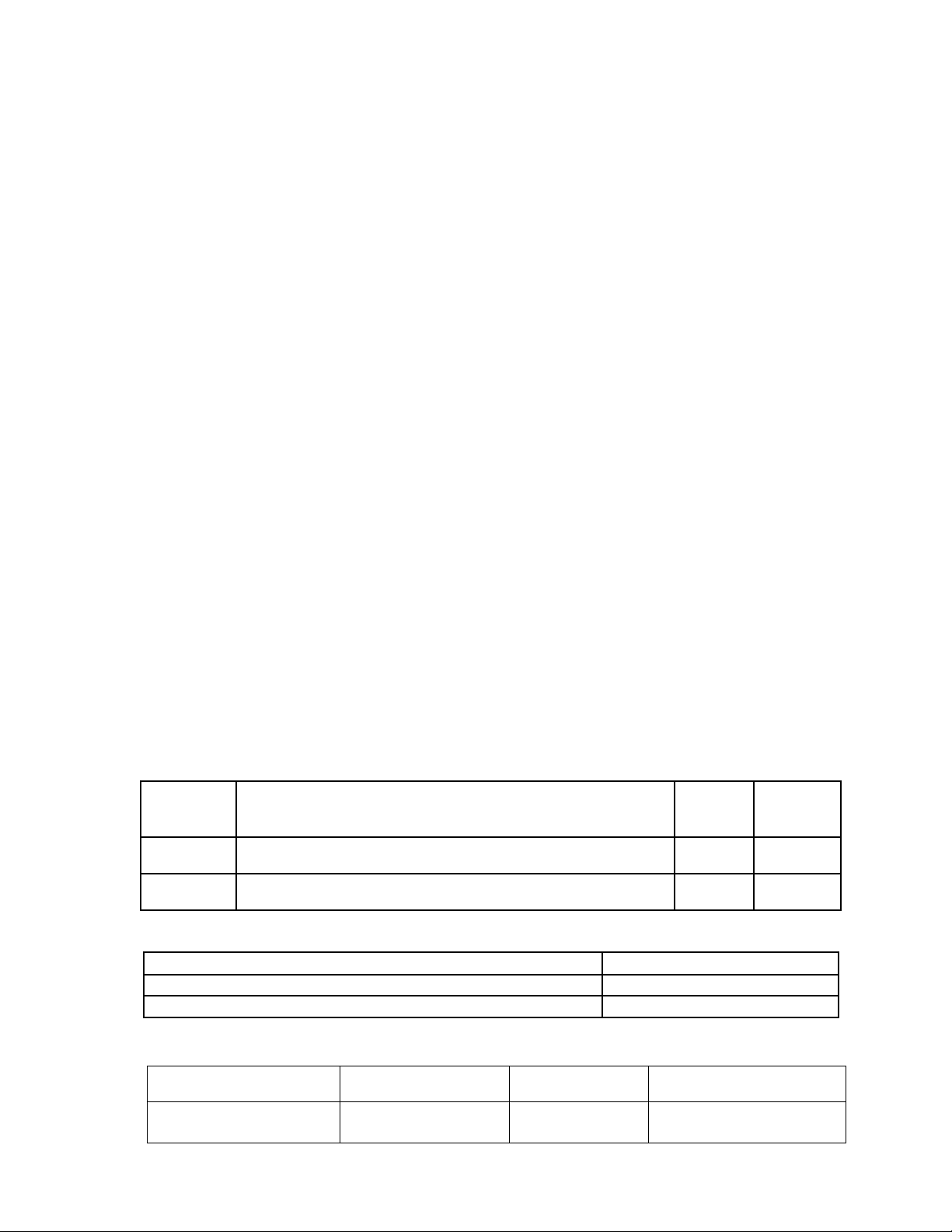
Vent Pipe Pipe Direction Enclosure Minimum Clearance To
Combustible Material, Inches
Concentric Venting
80/125 mm, 100/150 mm Vertical Or Horizontal Enclosed at All Sides 0
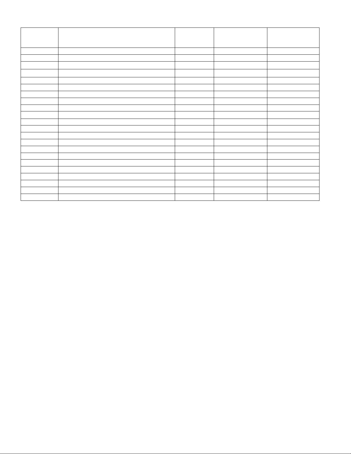
Table 5: Clearances from Vent Piping to Combustible Material
Table 3: Vent System Congurations
Table 4: Vent System Components Included with Boiler
Conguration Description Additional
Vent Kit
Required
Installation
Figure
1. Horizontal Direct Vent (sealed combustion) the concentric vent pipe terminates
horizontally (through a sidewall). No 4
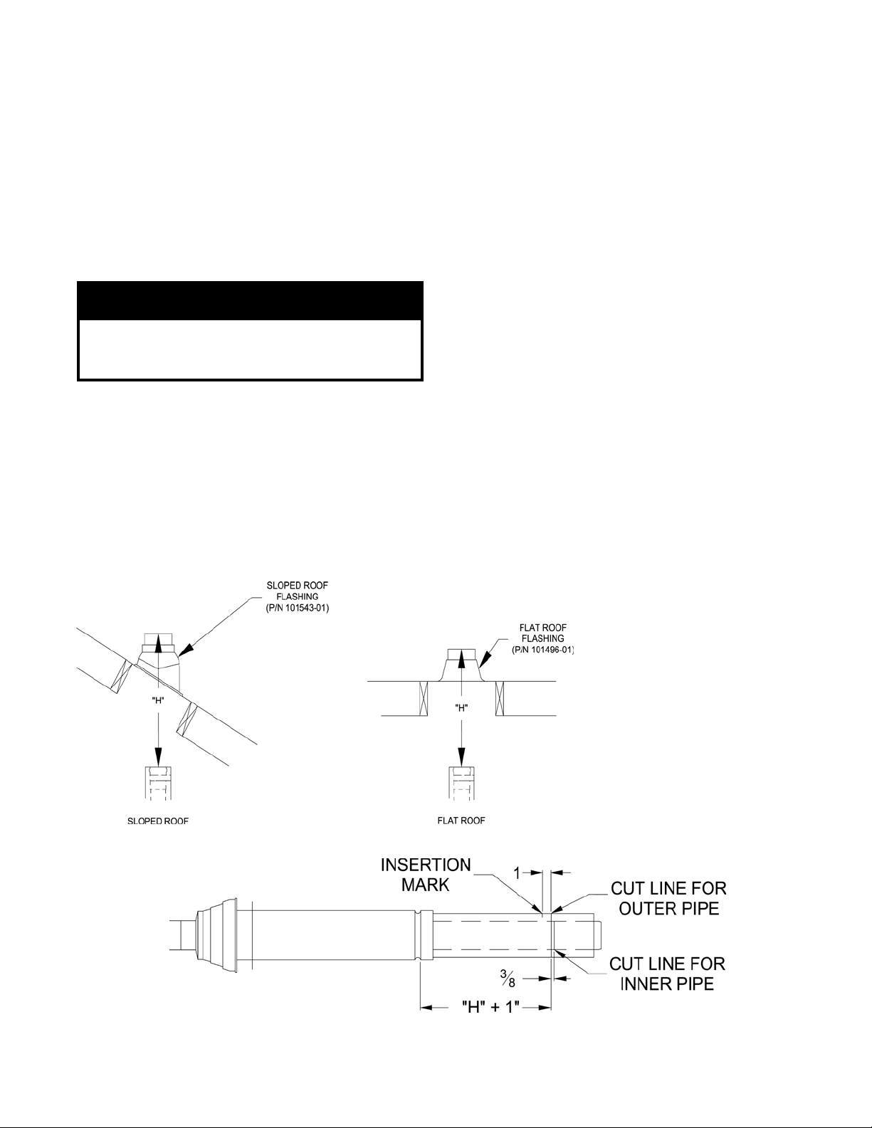
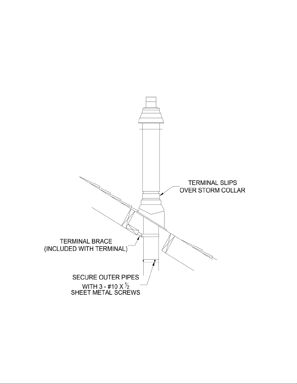
2. Vertical Direct Vent (sealed combustion) the concentric vent pipe terminates vertically
(through the roof). Yes 5
Vent System Components Part Number
80/125mm Horizontal (Wall) Terminal (ALP080 thru ALP210) 101808-01
100/150mm Horizontal (Wall) Terminal (ALP285 thru ALP399) 101809-01
C. General Guidelines
1. Vent system installation must be in accordance
with National Fuel Gas Code, NFPA 54/ANSI
Z221.3 or applicable provisions of local building
codes. Contact local building or re ofcials about
restrictions and installation inspection in your area.
2. Refer to the appropriate drawings in this section of
this manual to determine the proper conguration of
venting system. See Table 3.
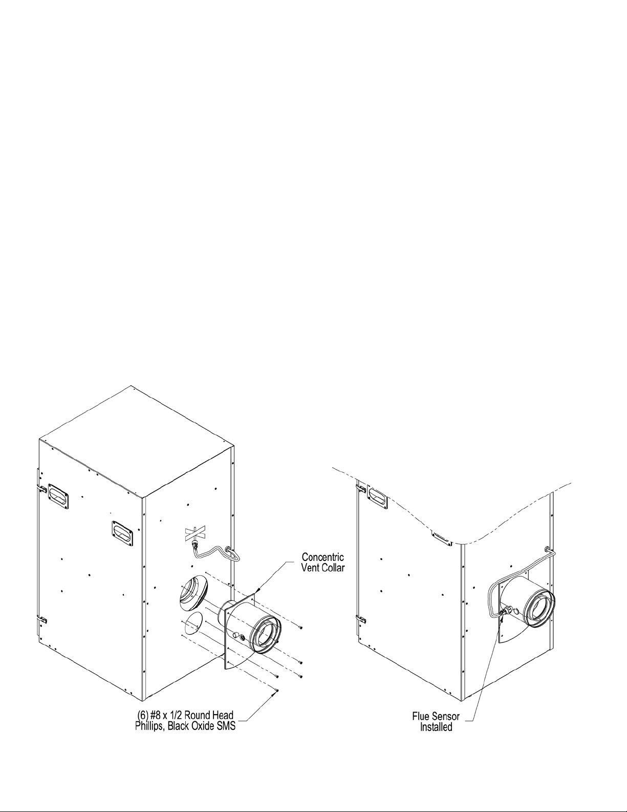
3. This appliance requires a special combination
Concentric Gas Vent / Air Inlet. Concentric vent
consists of inner re resistant polypropylene vent
pipe and outer steel pipe casing. The inner pipe
serves as conduit to expel products of combustion,
while outdoor fresh air for combustion is drawn
through the space between the inner and outer pipes.
4. Horizontal vent pipe must maintain a minimum ¼
inch per foot slope towards the boiler.
5. Use noncombustible ¾ inch pipe strap to support
horizontal runs and maintain vent location and
slope while preventing sags in pipe. Do not restrict
thermal expansion or movement of vent system.
Maximum support spacing is ve (5) feet. Do not
penetrate any part of the vent system with fasteners.
6. Vent length restrictions are based on equivalent
length of vent pipe i.e. total length of straight
pipe plus equivalent length of ttings. See Table
6 for specied vent length details. D not exceed
maximum vent length. Table 7 lists available
concentric vent components and includes equivalent
vent length for ttings. Do not include vent terminal
into total vent length calculations.
7. Provide and maintain vent pipe minimum clearances
to combustible material. See Figure 2B and Table 5
for details.
8. Provide minimum service clearance between boiler
back and concentric vent exiting through outside
wall, for concentric vent installation/replacement
and/or ue temperature sensor service/replacement,
as follows:
a. For horizontal venting where supplied
Concentric Vent Terminal is attached directly to
installed Boiler Concentric Vent Collar - 6 inches
b. For vertical venting where optional Concentric
Vent 90° long radius elbow is attached to
installed Boiler Concentric Vent Collar - 18
inches
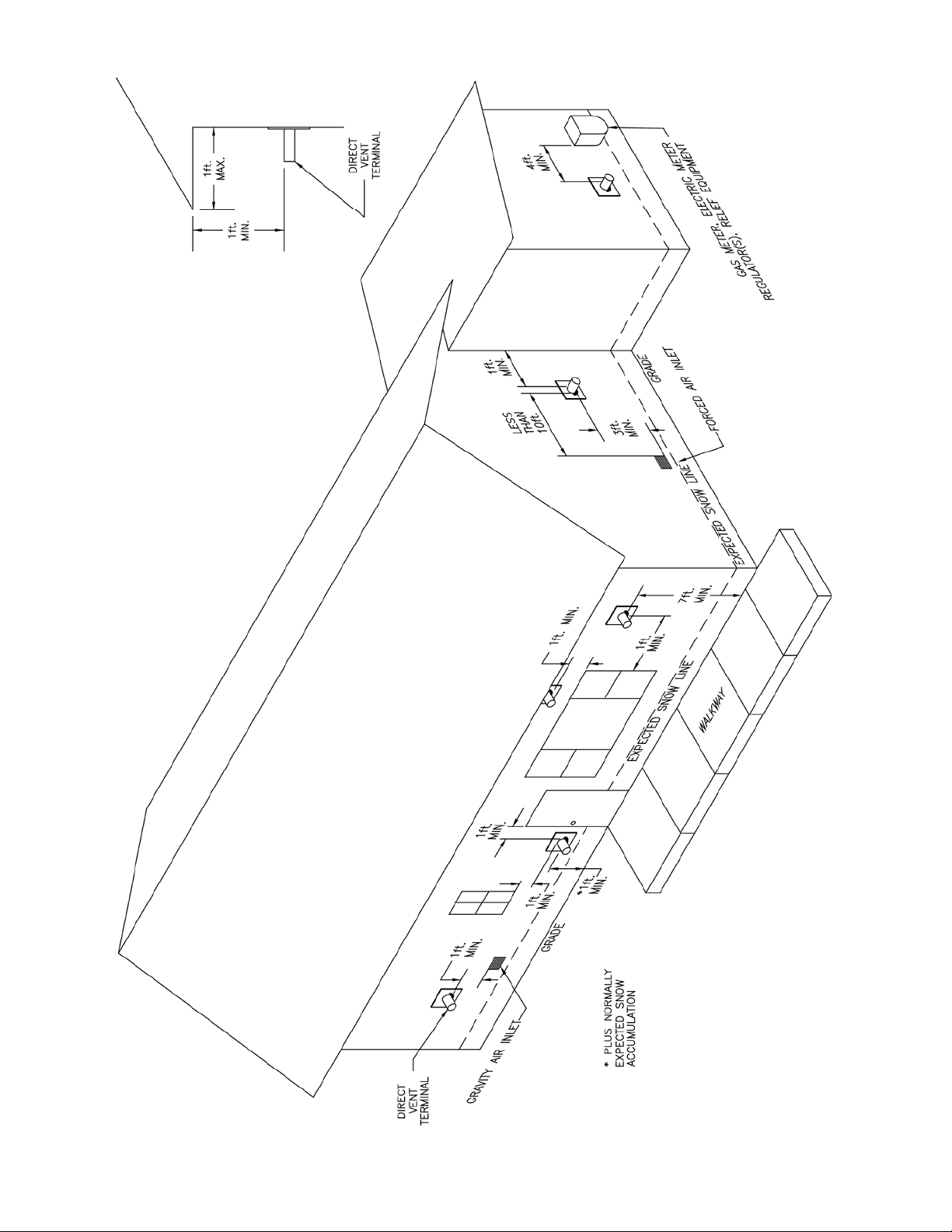
9. Do not install venting system components on the
exterior wall of the building except as specically
required by these instructions. Refer to Figure 3.
The direct vent termination location is restricted as
follows:
a. Minimum twelve (12) inches above grade plus
normally expected snow accumulation level, or
minimum seven (7) feet above grade, if direct
vent terminal is located adjacent to public
walkway. Do not install the terminal over public
walkway where local experience indicates that
appliance ue gas vapor or condensate creates a
nuisance or hazard.
b. Minimum three (3) feet above any forced air
inlet located within ten (10) feet.
c. Minimum four (4) feet horizontally from electric
meters, gas meters, regulators and relief valves.
This distance may be reduced if equipment is
protected from damage due to ue gas vapor or
condensation by enclosure, overhang, etc.
d. Minimum twelve (12) inches below, above or
horizontally from any air opening into a building
(window, door or gravity air inlet).
e. Minimum twelve (12) inches horizontally from a
building corner.

12
Table 6: Vent Length
Boiler Model Concentric Vent Inner/Outer Pipe
Dia., mm
Vent Length Wall Opening Diameter
Minimum * Maximum
ALP080
Factory Supplied
Horizontal (Wall) Terminal 80/125 mm 21-7/8 in Total of 60
Equivalent ft.
5-1/2 in
ALP105
ALP150
ALP210
ALP285 Factory Supplied
Horizontal (Wall) Terminal 100/150 mm 32 in 6-1/2 in
ALP399
Note: * With optional concentric vent components. See Table 7 for details.
f. Minimum twelve (12) inches vertically from any
roof overhang twelve (12) inches or less wide.
If a roof overhang width exceeds twelve (12)
inches the terminal vertical clearance must be
increased to avoid ue vapor condensation.
10. Enclose vent passing through occupied or
unoccupied spaces above the boiler with material
having a re resistance rating of at least equal to the
rating of the adjoining oor or ceiling. Maintain
minimum clearances to combustible materials. See
Figure 2B.
Note: For one or two family dwellings, re
resistance rating requirement may not need to be
met, but is recommended.
11. Plan venting system to avoid possible contact with
plumbing or electrical wires. Start at vent connector
on top of boiler and work towards vent terminal.
12. Permitted terminals for horizontal venting:
Horizontal (Wall) Terminal, either 80/125 mm (P/N
101808-01) or 100/150 mm (P/N 101809-01) - see
Table 7.
13. Concentric Vent components supplied with the boiler
are packed inside boiler carton and include the
following:
a. 80/125 mm Horizontal (Wall) Terminal, Part
Number 101808-01
Figure 2B: Clearances To Combustible and Non-combustible Material

13
Figure 3: Location of Vent Terminal Relative to Windows, Doors, Grade, Overhangs, Meters and Forced Air Inlets

14
• Horizontal (Wall) Terminal consists of
Straight section having plain male end with
locking band clamp installed; Terminal
Assembly with offset vent termination,
and Outside Wall Plate, both riveted
on the opposite end; overall length is
approximately 28-1/8”.
• Separate Inside Wall Plate
• Two Hardware Bags (each bag contains
four screws and four anchors) to attach vent
terminal Outside Wall Plate to exterior wall
and Inside Wall Plate to interior wall.
b. 100/150 mm Horizontal (Wall) Terminal, Part
Number 101809-01
• Horizontal Concentric Vent Terminal, which
consists of Straight section having plain
male end with locking band clamp installed;
Terminal Assembly with offset vent
termination, and Outside Wall Plate, both
riveted on the opposite end); overall length
is approximately 31-1/8”.
• Separate Inside Wall Plate.
• Two Hardware Bags (each bag contains
Table 7: Concentric Vent Components
Part Number Component Description Size Component
Equivalent Vent
Length, Ft Comments
101542-01 90° Elbow – Long Radius 80/125 mm 5.5
101908-01 45° Elbow - Long Radius 80/125 mm 3.0
101163-01 Cut -To-Length Extension,500 mm (19-1/2”) 80/125 mm 1.63 **Can be cut
101162-01 Cut -To-Length Extension, 1000 mm (39”) 80/125 mm 3.25 **Can be cut
101485-01 Fixed Extension, 2000 mm (78”) 80/125 mm 3.25 ***Must not be cut
101808-01 Horizontal (Wall) Terminal 80/125 mm *NA Supplied with boiler
101495-01 Vertical Roof Terminal 80/125 mm *NA See Note 1
101496-01 Flat Roof Flashing 80/125 mm
101543-01 Sloped Roof Flashing 80/125 mm See Note 2
101492-01 Support Elbow with Chimney Chase Bracket 80/125 mm 8.5 See Note 3
101498-01 Hanger 80/125 mm
101548-01 90° Elbow – Long Radius 100/150 mm 8.0
101549-01 45° Elbow - Long Radius 100/150 mm 3.0
101550-01 1 Cut -To-Length Extension,500 mm (19-1/2”) 100/150 mm 1.63 ** Can be cut
101551-01 Cut -To-Length Extension,1000 mm (39”) 100/150 mm 3.25 ** Can be cut
101553-01 Fixed Extension, 2000 mm (78”) 100/150 mm 6.5 *** Must not be cut
101809-01 Horizontal (Wall) Terminal 100/150 mm * NA Supplied with boiler
101557-01 Vertical (Roof) Terminal 100/150 mm * NA See Note 1
101558-01 Flat Roof Flashing 100/150 mm
101559-01 Sloped Roof Flashing 100/150 mm See Note 2
101560-01 Support Elbow with Chimney Chase Bracket 100/150 mm 10.0 See Note 3
101561-01 Hanger 100/150 mm
Notes:
* NA – do not include vent terminal into total vent length calculations.
** These sections have plain male end and beaded female end. See Figure 11 for details.
*** These sections have beaded male end and beaded female end. See Figure 12 for details.
1. Vertical terminal can be used with either of the roof ashings listed beneath it.
2. Sloped roof ashing suitable for roof angles between 25° and 45°.
3. Used at base of vertical run inside unused masonry chimney.
four screws and four anchors) to attach vent
terminal Outside Wall Plate to exterior wall
and Inside Wall Plate to interior wall.
14. Installation of the Boiler Concentric Vent Collar is
covered in Section B above. See Figure 2A.
15. For horizontal (side wall) installation, the Horizontal
(Wall) Terminal will extend past outer wall surface
either by 4-1/4” (80/125 mm), or, 5-1/2” (100/150
mm). See Figure 4 “Horizontal (Wall) Terminal
Installation”.
16. For vertical (through the roof) venting, extend
Vertical (Roof) Terminal to maintain minimum 12
inches vertical and horizontal distance from building
roof surface. Allow additional vertical distance
for expected snow accumulation. Provide brace as
required. See Figure 5 ‘Vertical Concentric Vent
Installation’.
17. For horizontal venting, to install the Horizontal
(Wall) Terminal:
a. Cut a 5-1/2” diameter hole through the exterior
wall opening (for 80/125 mm concentric vent) or
6-1/2” diameter hole (for 100/150 mm concentric

15
vent) at the planned location of the horizontal
terminal.
b. Measure dimension “L” from exterior wall outer
surface to the end of the last tting (or end of
installed Boiler Concentric Vent Collar). See
Figure 6 ‘Dimension “L”’.
c. When factory supplied Horizontal (Wall)
Terminal needs to be shortened, measure
dimension “L” plus 1-¼” from inside of the
Figure 5: Vertical (Roof) Terminal Installation
Figure 4: Horizontal (Wall) Terminal Installation
attached Outside Wall Plate and mark the
Horizontal (Wall) Terminal outer pipe. To
achieve a square cut of the outer pipe, place
several marks around the outer pipe to establish a
cut line. See Figure 7 ‘ Cutting Outer Pipe’.
d. Carefully cut the outer pipe at the marked line
using aviation shears, a hacksaw etc. Ensure the
pipe is cut square and cut end is deburred.
e. Mark the end of the Horizontal (Wall) Terminal
inner polypropylene vent pipe to extend ¾” past
the cut end of the outer pipe. To achieve a square
cut of the inner pipe, place several marks around
the inner pipe to establish a cut line.
f. Cut off the marked end of inner polypropylene
vent pipe with a ne tooth blade hacksaw etc.
and deburr. See Figure 8 “Cutting Inner Pipe.
g. Place a mark around the outer pipe, 1” from cut
edge, towards the attached Outside Wall Plate, to
establish visual insertion line as shown in Figure
8 “Cutting Inner Pipe”.
h. Pass the shortened Horizontal Concentric Vent
from outside, thru earlier cut exterior wall
opening and push in until the attached Outside
Wall Plate is tight against exterior wall surface.
Insure the proper position of the Horizontal
Concentric Vent before securing the Outside Wall
Plate to the wall with provided fasteners. Seal
plate edges with exterior grade sealant to prevent
moisture penetration.

16
Figure 6: Dimension “L”
Figure 7: Cutting Outer Pipe
GNINRAW
sdrawottesffosinoitroptnevlanimretehT
-noziroHehtfoepipretuoehtedisnipoteht
tnevedivorpotlanimreTtneVcirtnecnoClat
rofreliobehtsdrawothctipepip
.lavomeretasnednoc
lanimreT)llaW(latnoziroH'9erugiFeeS
tnuomylreporpotevitarepmisitI.'liateD
.lanimrettneveht
nodetacolsilebalnoitatneirolanimretehT
.etalPllaWedistuOlanimretehtfoedisnieht
sadenoitisopsilanimrettnevehterusnI
ehtgniruceserofeb01erugiFninwohs
.llawroiretxeotetalPllaWedistuO
Figure 8: Cutting Inner Pipe
NOITUAC
ylbanosaerebtsumecafrusllawroiretxE
nehW.etalPllaWedistuOehthcattaottalf
derevoc(talftonsiecafrusllawroiretxe
eht).ctegnidiselgnihsdoowrolynivhtiw
ecafrustalfadna,devomerebtsumgnidis
roiretxegnidisevobarohsalfpudliub
edistuOlanimretehtlaes/erucesotecafrus
.etalPllaW
i. Install the supplied Inside Wall Plate onto the
shortened Horizontal (Wall) Terminal interior
end and move the plate to cover interior wall
cut opening. Secure the plate with provided
fasteners, then, apply the sealant around plate
sides to seal it to interior wall.
j. Lubricate the brown gasket inside boiler
concentric vent collar or the last section of the
vent pipe with small amount of water.
k. Ensure that inner pipe of the terminal is evenly
engaged into the gasket all around, then push the
termination male end inside boiler concentric
vent collar or the last section of the vent pipe,
until the mark (see Step g) is no longer visible.
Figure 9: Horizontal (Wall) Terminal Detail
l. Re-install locking band clamp onto the joint
to secure the terminal to the collar or the last
section of the vent pipe.
18. Additionally, secure vent terminal to boiler vent
collar, or, last section of the vent pipe with installer
provided three evenly spaced #8 x ½” sheet metal
screws. Mark (center punch) each screw location
thru the middle of the locking band clamp, then,
drill 1/8” holes thru locking band and both vent
terminal and boiler collar outer pipes to start the
screw. Use drill stop or other means to ensure the
drill bit does not penetrate more than 3/8” into the
outer pipe. Do not use screws longer than ½”.
19. For vertical venting, where optional Concentric Vent
90°degree long radius elbow is attached to installed
Boiler Concentric Vent Collar, to install elbow:

17
b. The remaining Concentric Vent Fixed Extensions
shown in Table 7 CANNOT BE CUT. These
pipes have beaded male and beaded female ends.
See Figure 12 ‘Fixed Extension (Non-Cuttable)’.
a. Remove locking band clamp off the terminal and
set aside.
b. Lubricate the brown gasket inside boiler
concentric vent collar with small amount of
water.
c. Ensure that male end of the elbow inner plastic
pipe is evenly engaged into the gasket all around,
then, push the elbow male end inside boiler
concentric vent collar until the bead on male end
of elbow outer pipe bottoms out inside boiler
vent collar.
d. Re-install locking band clamp onto the joint to
secure the elbow to the collar.
e. Continue installing additional concentric vent
cuttable or non-cuttable piping as required.
20. Additionally, secure elbow to boiler vent collar with
three evenly spaced #8 x ½” sheet metal screws.
Use collar rivets as reference attachment points.
Mark (center punch) each screw location off each
rivet centerline 5/8” towards collar-beaded end. See
Figure 10 ‘Completing Horizontal (Wall) Terminal
Installation’ for details. Drill 1/8” hole thru both
outer pipes to start the screw. Use a drill stop or
other means to ensure that the drill bit does not
penetrate more than 3/8” into the outer pipe. Do
not use sheet metal screws longer than ½”.
21. If additional concentric vent piping is needed:
a. Concentric Vent Cut-To-Length Extension pipes,
identied in Tables 7 and 8 CAN BE CUT
to required length when used as an extension.
These pipes have plain male end and beaded
female end. Always cut the pipe from plain
male end. See Figure 11 ‘Cut-To-Length
Extension (Cuttable)”.
Figure 10: Completing Horizontal (Wall)
Terminal Installation
Table 8: Cut-To-Length Extensions (Cuttable)
Part No. Component Description Size
101163-01 Cut-To-Length Extension,
500 mm (19-1/2”) 80/125 mm
101162-01 Cut-To-Length Extension,
1000 mm (39”)
101550-01 Cut-To-Length Extension,
500 mm (19-1/2”) 100/150 mm
101551-01 Cut-To-Length Extension,
1000 mm (39”)
Figure 11: Cut-To-Length Extension (Cuttable)
Figure 12: Fixed Extension (Non-Cuttable)
22. To cut the Concentric Vent Straight pipe to required
length refer to Figure 13 “Cutting Straight Pipe” and
follow the procedure below:
a. Determine the required length of the outer pipe.
When doing this allow an additional 1” of length
for insertion into the female end of the adjoining
pipe. Mark the cut line on the outer pipe.
b. Remove the plastic inner pipe by pulling it out
from the female end.
c. Cut the OUTER PIPE ONLY at the point
marked in Step (a) using aviation shears, a
hacksaw, or an abrasive wheel cutter. Be careful
to cut the pipe square. Deburr the cut end with a
le or emery cloth.
d. Make an insertion mark 1” from the male end of
the outer pipe.
e. Cut the plastic inner pipe so that it will protrude
3/8” beyond the male end of the outer pipe when
reinstalled in the outer pipe. Use a ne tooth
hacksaw or a PCC saw to cut the plastic pipe and
be careful to cut the pipe square. Deburr the cut
edge of the plastic pipe with a le, razor blade or
ne sandpaper.
f. Reinstall the inner pipe.

18
Figure 13: Cutting Straight Pipe
Figure 14: Joining Cuttable Pipe
23. To join Concentric Vent Pipe refer to Figure 14
“Joining Cuttable Pipe” and Figure 15 “Joining
Non-Cuttable Pipe” and follow the procedure below:
a. Start assembly of the vent system at the boiler.
Lubricate the brown gasket in the boiler vent
collar with a few drops of water.
b. Push the male end of the rst tting into the
boiler collar until it bottoms out. The male
end of cuttable sections should go 1” into the
collar until the insertion mark (made in Step 22d
above) is covered. On other ttings, the bead on
the male pipe will be bottom out on the collar
(see Figure 15).
c. The male end of cuttable ttings must be held to
the collar with three (3) #10 x 1/2” sheet metal
screws. Drill a 1/8 hole through both outer pipes
to start this screw. Use a drill stop or other
means to ensure that the drill bit does not
penetrate more than 3/8” into the outer pipe.
Do not use a sheet metal screw longer than
1/2” (see Figure 14).
d. Use locking bands (provided with all ttings) to
secure non-cuttable pipe, as well as ttings, to
the boiler collar (see Figure 15).
e. Use the same method to join all remaining vent
components except for the terminal. Figure 15: Joining Non-Cuttable Pipe

19
24. Vertical (Roof) Terminal Installation. Refer to
Figures 17, 18 and 19.
In addition to the vertical terminal, either a Flat
Roof Flashing or Sloped Roof Flashing is required
for this installation. Refer to Table 7 ‘Concentric
Vent Components’ for details.
a. Determine the centerline of the terminal location
on the roof. For at roof, cut either 5-1/2”
diameter hole (80/125 mm concentric vent size)
or 6-1/2” diameter hole (100/150 mm concentric
vent size) for the terminal. For sloped roof, cut a
hole in the roof large enough for the terminal to
pass through the roof while remaining plumb.
NOITUAC
ehtrednuyltceriddetacolsireliobehtfI
otelohehtgnittucelihwtirevoc,eloh
.reliobotnognillafmorfsirbedtneverp
b. Install the roof ashing using standard practice
on the roong system of the structure.
c. If not already done, assemble the venting system
inside the building. The last section of pipe needs
to be on the same center line as the terminal
and within 19-1/4” of the top edge of the roof
ashing ( ).
d. Measure distance “H” from the top edge of the
storm collar to the end of the last tting as shown
in Figure 16.
Figure 16: Dimension "H"
e. Add 1” to distance “H”. Carefully mark this
length on the pipe as shown in Figure 17.
f. Cut the outer pipe only at the point marked in
Step (e) using aviation shears, a hacksaw, or an
abrasive wheel cutter. Be careful to cut the pipe
square. De-burr the cut end with a le or emery
cloth.
g. Place a mark on the plastic inner pipe 3/8”
beyond the end of the outer pipe (Figure 18).
Use a ne tooth hacksaw to cut the plastic pipe
and be careful to cut the pipe square. De-burr the
cut edge of the plastic pipe with a le or emery
cloth.
h. Make a mark on the terminal section 1” from the
cut end of the outer pipe as shown in Figure 17.
i. Slip the terminal section through the roof from
the outside. Push into the last section of vent
pipe until the mark made in Step (h) is not
longer visible. Secure the terminal to the last
piece of pipe with three #10 x 1/2” sheet metal
screws. Drill a 1/8” hole through both outer
pipes to start these screws. Use a drill stop or
other means to ensure that the drill bit does
not penetrate more than 3/8” into the outer
pipe. Do not use a sheet metal screw longer
than 1/2”.
j. Secure the terminal section to the inside of
the roof structure using the mounting bracket
provided with the terminal (Figure 18).
Figure 17: Cutting Vertical Terminal

20
Figure 18: Completing Vertical Terminal Installation
25. Chimney Chase Installation.
A vertical concentric vent system, either 80/125 mm
or 100/150 mm can be installed in an UNUSED
masonry chimney. Refer to Figure 19.
a. The Chimney chase Support Elbow with
attached Mounting Bracket is used at the base
of the chimney. Refer to Table 7 ‘Concentric
Vent Components’ for details. Slip the elbow
over the M10 x 35 screw in the support bracket.
Determine the desired vertical location of the
support elbow in the chimney and mark the
location of the pin, positioned on the back of
the support bracket, onto the chimney rear wall.
Drill a 7/16” diameter x 3-1/2” deep hole in the
marked location, then, insert the back bracket pin
into the hole. The front of the elbow mounting
bracket should be supported either by bottom of
the opening into chimney or installer supplied
spacer.
b. Construct a weather-tight at roof to cover
the top of the old chimney. Install the vertical
terminal through this roof using the at roof
ashing.
This manual suits for next models
5
Table of contents
Other Boiler Company Boiler manuals
Popular Boiler manuals by other brands

Viessmann
Viessmann Vitocrossal 200 CM2 186 Service instruction

First Choice
First Choice Zip Hydroboil Plus manual

M&G
M&G DuraVent DIS installation instructions

Worcester
Worcester GREENSTAR 24i junior instruction manual

Alde
Alde Comfort 2928 Instructions for use

VOKERA
VOKERA Mynute Installation & servicing instructions