Bond TIER 54 User manual

CEILING FAN INSTRUCTION MANUAL
INDOOR / OUTDOOR LED FAN
WET LED
54" TIER™

WARNING:
Read and follow these instructions carefully and be mindful of all warnings shown throughout.
TABLE OF CONTENTS
02 GENERAL INSTALLATION & OPERATING
INSTRUCTIONS
03 IMPORTANT SAFETY PRECAUTIONS
03 TOOLS & MATERIALS REQUIRED
04 UNPACKING YOUR FAN
05 PREPARATION
05 INSTALLING THE HANGING BRACKET
06 HANGING THE FAN
08 ELECTRICAL CONNECTIONS
09 FINISHING THE INSTALLATION
10 BLADE ATTACHMENT
10 INSTALLING THE MONTING PLATE
11 INSTALLING THE LIGHT KIT AND GLASS SHADE
12 INSTALLING THE WALL CONTROL
14 OPERATION
16 CARE AND CLEANING
16 TROUBLESHOOTING
17
17
18
SPECIFICATIONS
SMART BY BOND
ENERGY GUIDE

GENERAL INSTALLATION & OPERATION INSTRUCTIONS
1
2
3
4
5
6
7
8
9
10
11
12
13
14
To ensure the success of the installation, be sure to read the instructions and review the diagrams thoroughly before beginning.
To avoid possible electric shock, be sure electricity is turned off at the main power box before wiring. All electrical connections
must be made in accordance with local codes, ordinances and/or the National Electric Code. If you are unfamiliar with the
methods of installing electrical wiring and products, secure the services of a qualified and licensed electrician as well as
someone who can check the strength of the supportive ceiling members and make the proper installation(s) and connections.
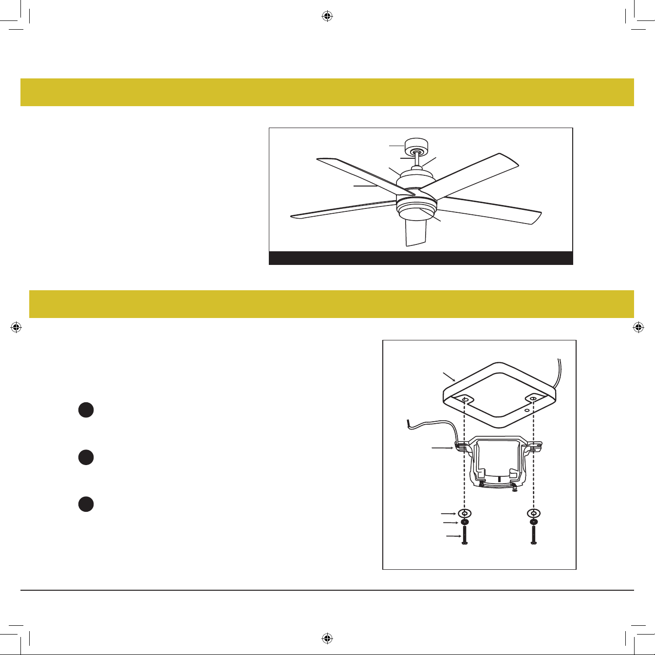
WARNING: To reduce the risk of fire, electric shock, or other personal injury, mount fan only on an outlet box or supporting system
marked acceptable for fan support of 35 lbs (15.9 kg) or less and use mounting screws provided with the outlet box. Most outlet
boxes commonly used for the support of lighting fixtures are not acceptable for fan support and may need to be replaced.
Consult a qualified electrician if in doubt.
Make sure that your installation site will not allow rotating fan blades to come in contact with any object. Blades should be at least
7 feet from floor.
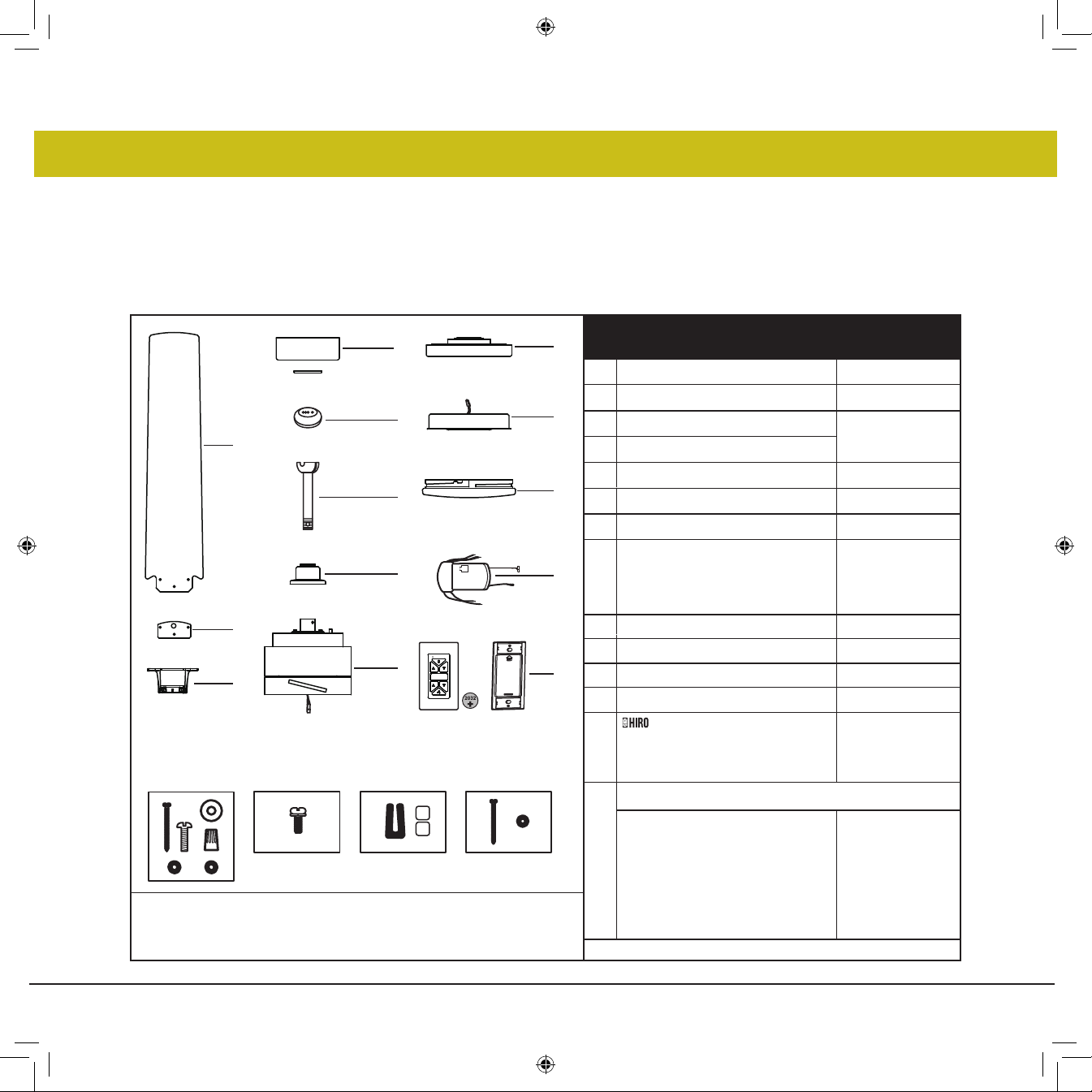
Blades should be attached after motor housing is hung and in place. Fan motor housing should be kept in the carton until ready
to be installed to protect its finish. If you are installing more than one ceiling fan, make sure that you do not mix fan blade sets, as
each blade is part of a weighted set.
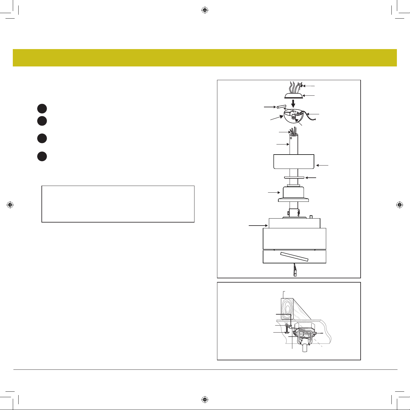
After making electrical connections, spliced conductors should be turned upward and pushed carefully up into outlet box. The
wires should be spread apart with the common conductor and the grounding conductor on one side of the outlet box, and the
"HOT" wires on the other side.
Electrical diagrams are for reference only. Light kits that are not packed with the fan must be UL listed and should be installed
per the light kit's installation instructions.
After fan is completely installed, check to make sure that all connections are secure to prevent fan from falling and/or causing
damage or injury.
The fan can be made to work immediately after installation - the bearings are adequately charged with grease so that, under
normal conditions, further lubrication should not be necessary for the life of the fan.
To operate the reverse function on this fan, press the reverse button while the fan is running.
CAUTION: Do not ingest battery - Chemical bum hazard. Keep new and used batteries away from children.
The remote control supplied with a coin/button cell battery. If the coin/button cell battery is swallowed, it can cause severe
internal bums in just 2 hours and can lead to death.
If the battery compartment does not close securely, stop using the product and keep it away from children.
If you think batteries might have been swallowed or placed inside any part of the body, seek immediate medical attention.

IMPORTANT SAFETY PRECAUTIONS
TOOLS & MATERIALS REQUIRED
WARNINGS:
• PHILLIPS SCREWDRIVER
• FLAT SCREWDRIVER
• WRENCH OR PLIERS
• WIRE CUTTER
• STEPLADDER
• WIRING SUPPLIES AS REQUIRED BY
ELECTRICAL CODE
• Disconnect power by removing fuse or turning off circuit breaker before installing the fan and/or optional lighting.
• Support directly from building structure.
• To reduce the risk of fire, electric shock or personal injury, mount to outlet box marked "acceptable for fan support" and use mounting
screws provided with the outlet box. Most outlet boxes commonly used for the support of lighting fixtures are not acceptable for fan
support and may need to be replaced. Consult a qualified electrician if in doubt.
• Do not use an incandescent light dimmer. Do not use this fan with any transformer type fan speed control device.
• To reduce the risk of personal injury, do not bend the blade arms when installing them, balancing the blades or cleaning the fan.
Do not insert any object(s) between rotating fan blades.
NOTE:
The important precautions, safeguards and instructions appearing in this manual are not meant to cover all possible conditions
and situations that may occur. It must be understood that common sense, caution and carefulness are factors which cannot be
built into this product. These factors must be supplied by the person(s) installing, caring for and operating the unit.

UNPACKING YOUR FAN
UNPACK YOUR FAN AND CHECK THE CONTENTS.
TIER PACKAGE CONTENT
1 Blade Set of 5 BL902054Fxx
2
Hanging Bracket
Blade support plates
3
Ceiling Canopy and Trim Ring4
5
6
7
8
9
10
11
12
13
14
1
6
14
3
5
8
10
9
2
11
12
13
• Do not discard the carton. If warranty replacement or repair is ever necessary, the fan should be returned in original packing.
Remove all parts and hardware. Do not lay motor housing on its side, or the decorative housing may shift, be bent or damaged.
• Examine all parts. You should have the following:
NOTE: Design of parts shown above may look slightly different for
your specific model of fan.
7
4
Downrod Asm.
Yoke cover
Adapter Plate
16W LED Assembly
Glass Shade
Hardware Bag
Ball Moisture Cover
Fan Housing with Motor
*Remove rubber shipping
supports around motor, if
applicable. Save the screws.
Bracket Mounting Hardware
(wood screws, screws, lock
washers, star washers, flat washers,
wire nuts),
Blade to Motor Screws
w/Lock Washers,
Balance Kit,
Safety cable hardware
(wood screw, flat washer)
In Hardware Bag
In Hardware Bag
MH902054Fxx
CA900752Fxx
DR94014Fxx
YC902054Fxx
X
CNW902054
AP902054Fxx
E902054LED
GL902054OPET
XX=FAN FINISH
+
Receiver Incl. 5 Wire Nuts
Cradle B (for flat wall use only)
Cradle A, Wall Plate, Face Plate,
2 Mounting Screws,
Wall Control w/2032 Battery,
980014FWH

PREPARATION
INSTALLING THE HANGING BRACKET
PREPARATION:
Parts identification on assembled fan.
1
2
3
Ceiling Fan
Outlet Box
Hanger
Bracket
Outlet Box
Screw
Flat Washer
Spring Washer
Fig. 1
Verify you have all parts before beginning
the installation. Check foam insert closely for
missing parts. Remove motor from packing.
To avoid damage to finish, assemble motor
on soft padded surface or use the original
foam inset in motor box.
DO NOT LAY MOTOR HOUSING ON ITS SIDE
AS THIS COULD RESULT IN SHIFTING OF
MOTOR IN DECORATIVE ENCLOSURE.
CAUTION: To avoid possible electrical shock, be sure electricity is turned off
at the main power box before wiring. All wiring must be in accordance with
National and Local Electrical Codes and the ceiling fan must be grounded as
a precaution against possible electric shock.
Locate ceiling joist where fan is to be mounted, being sure location
agrees with the requirements in the minimum clearance section of this
guide. Wood joists must be sound and of adequate size to support 35
pounds (See page 2, items 3 and 4).
If not already present, mount a UL listed outlet box marked "suitable for
fan support" following the instructions provided with the outlet box. The
outlet box must be able to support a minimum of 35 pounds.
Attach hanging bracket to outlet box using screws provided with the
outlet box.
Blade
Yoke Cover
Downrod
Canopy
Motor Housing
LED Light Kit

HANGING THE FAN
1
2
3
4
5
Fig. 1
Fig. 2
Downrod
Cross pin
Hanger
ball Set screw
Downrod
Hook-up
(3) Wires
Mounting Collar
Downrod Pin
Security Screws
Cotter Pin
Top of
Fan Body
Remove ball from downrod by loosening set screw in the
side of the ball. Slide ball down and remove ball pin; remove
ball. (Fig. 1)
Carefully support fan body (motor) in its styrofoam packing
with the mounting collar (where the wires come out) facing
upward.
Loosen the two security set screws and remove the downrod
pin and retaining clip from the coupling on top of the motor
assembly. (Fig. 2)
Carefully feed the electrical lead wires and safety cable from
the fan through the downrod. Thread downrod into coupler
until holes align. Insert downrod pin through holes in
mounting collar and downrod; clip cotter pin through small
hole in end of downrod pin to hold downrod in place.
Tighten security set screws against downrod using a large
flat blade screwdriver to ensure a tight fit against downrod.
Tighten nuts against mounting collar.
Safety Cable

Fig. 3
Ground Wire
Top of
Fan Body
Hook-up (3) Wires
Yoke Cover
Downrod
Canopy
Hanger ball
Set screw
Cross Pin
Ball Moisture Cap
REMEMBER to turn off the power before you begin.
To properly install your ceiling fan, follow the steps below.
Slip the yoke cover, trim ring and canopy onto the downrod. (Fig. 3)
Slide the hanger ball onto the downrod, insert the cross pin through
the downrod and tighten. Tighten the set screw.
Feed wires through holes in rubber ball moisture cap and slide cap
down over top of ball. (Fig. 3)
Lift ball/downrod/fan into hanger bracket opening.
NOTE: The tab opposite hanger bracket opening should fit in slot
on ball. (Fig. 4)
6
7
8
9
NOTE:
6 feet of lead wire is supplied on the fan for use with
longer downrods.
Trim Ring
Safety Cable
Fig. 4
Attach the wood screw and the flat washer to the ceiling joist as
shown (do not fully tighten). Slide the cable clamp onto the
safety cable from the fan. Loop the safety cable around the
wood screw that was just attached to ceiling joist. Feed the end
of the cable into the clamp and pull as much cable through as
possible. Firmly tighten screw in the clamp. Cut off excess cable.
INSTALLATION OF SAFETY CABLE SUPPORT
Safety Cable Clamp
Safety Cable
Wood Ceiling Joist
Safety Cable Loop
Wood Screw
And Washer

ELECTRICAL CONNECTIONS
1
2
3
I
nsert the receiver into the ceiling mounting bracket with
the flat side of the receiver facing the ceiling. (Fig. 1) For
best performance, make sure the Black Antenna, on the
end of the receiver, remains extended and not tangled
with any of the electrical wires.
Motor to Receiver Electrical Connections: (Fig. 2)
Connect the black wire from the fan to the black wire
marked "TO MOTOR L" on the receiver. Connect the
white wire from the fan to the white wire marked "TO
MOTOR N" on the receiver. Connect the blue wire from
the fan to the blue wire marked "FOR LIGHT" on the
receiver. Secure all the wire connections with the plastic
wire nuts provided.
Receiver to House Supply Wires Electrical Connections:
(Fig. 2) Connect the black (hot) wire from the ceiling to
the black wire marked "AC in L" from the receiver.
Connect the white(neutral) wire from the ceiling to the
white wire marked "AC in N" from the Receiver. Secure
the wire connections with the plastic wire nuts provided.
REMEMBER -Turn off the power! NOTE - Control must be installed
within 30 feet of fan.
WARNINGS: Check to see that all connections are tight, including
ground, and that no bare wire is visible at the wire nuts, except for
the ground wire.
CAUTION: To reduce the risk of electric shock, this fan must be
installed with an isolating wall control/switch.
Fig. 1
Receiver
Hanger
bracket
Fig. 2
Receiver
White (neutral)
White (neutral)
Green or bare
copper (ground)
White ("AC IN N")
White ("to motor N")
Ground
(green)
(Connect to
ground wire on
hanger bracket
if no house
ground wire
exists.)
Outlet box
Black (hot)
Black ("AC IN L")
Black ("to motor L")
Blue (for light)
Blue (for light)
Black (motor)

FINISHING THE INSTALLATION
1
2
3
Tuck connections neatly into ceiling outlet box.
Slide the canopy up to mounting bracket and place the
key hole on the trim ring the screw on the mounting
bracket, turn canopy until it locks in place at the narrow
section of the key holes.
Align the circular hole on canopy with the remaining
hole on the mounting bracket, secure by tightening the
two set screws.
NOTE: Adjust the canopy screws as necessary until the
canopy and trim ring are snug.
Canopy
Screws
Trim Ring
Ceiling Fan
Outlet Box
Hanger
Bracket Groove
WARNING:
Make sure the hook on the hanging bracket properly sits in the groove in the hanger ball before
attaching the canopy to the bracket by turning the housing until it drops into place.

INSTALLING THE MONTING PLATE
BLADE ATTACHMENT
CAUTION: Remove the two rubber packing mounts from the fan
motor assembly and discard prior to attaching the blades.
Insert the blade through the slot on the housing. Align the holes
on the blade and the fan motor assembly and secure with the
blade support plates and blade attachment screws.
NOTE:
Cordless power screwdrivers are NOT recommended,
as they usually strip the heads of the screws and
usually will not fully compress the lock washers on
the motor screws. Use a large flat blade screwdriver
for final tightening to fully compress the washers. This
will help ensure proper alignment of the blades and
noise-free, wobble-free running.
Blades
Blade
support
plates
Screws
Screws
Mounting Hub
(bottom of motor)
Adapter
plate
Light Wires
1
2
3
NOTE: Be sure the power is off before installing.
Remove one of the three screws on the mounting hub located
on the fan motor. Loosen the other 2 screws. (Do not remove)
(Fig. 1)
Pass the light wires through the center hole of the adapter
plate.
Place the key holes on the adapter plate over the 2 screws
previously loosened, turn the adapter plate until it locks in
place at the narrow section of the key holes. Secure by
tightening the 2 screws previously loosened and the one
previously removed.
Fig. 1

INSTALLING THE LIGHT KIT AND GLASS SHADE
1
2
3
4
5
NOTE: Be sure the power is off before installing.
Remove one of the three screws on the adapter plate located
on the fan motor. Loosen the other 2 screws. (Do not remove)
(Fig. 2)
While holding the LED light kit under your fan, make the
polarized plug connections: (Fig. 2)
- Red to white
- Black to black
Tuck connections neatly into adapter plate. Place the key
holes on the light kit over the 2 screws previously loosened,
turn the light kit until it locks in place at the narrow section of
the key holes. Secure by tightening the 2 screws previously
loosened and the one previously removed.
Raise the glass shade against the LED light kit and turn
clockwise until snug, DO NOT OVERTIGHTEN.
Restore power and your light kit is ready for operation.
Screws
Light Kit
Wire connectors
Glass shade
Fig. 2

5
5
INSTALLING THE WALL CONTROL
Fig. 1
Fig. 2
REMEMBER to turn off the power before you begin.
NOTE - Secures to any surface or application: flat wall, single gang
box, multi gang box.
1
2
3
4
Outlet box
Option 1. Flat Surface Installation
Select a desired location. Use the wall plate to mark the
location of the mounting holes. Plastic wall anchors or
mounting screws are needed for this application. (Fig. 1)
Seat the cradle B into the wall plate. Secure the wall plate to
the wall using the provided hardware.
Snap the face plate cover onto the wall bracket.
Remote transmitter will be held in place with built in magnets.
Remove the existing wall plate and the old switch from the wall outlet
box.
Seat the cradle A into the wall plate. (Fig. 2)
Connect the black lead wires from the switch in the cradle A to the
black wires in the switch box. Hot input wire to one of the cradle A
switch leads. Power lead to the fan is connected to the remaining
switch lead.
Connect the wall plate / cradle A assembly to the wall outlet box
using the supplied hardware.
Snap the face plate cover onto the wall bracket.
Remote transmitter will be held in place with built in magnets.
1
2
3
4
5
6
Option 2. For single gang box
Transmitter
Transmitter
Face plate
Face plate
Wall plate
Wall plate
Cradle B
Cradle A
Wall
Plastic
anchor
HIRO Control System

Fig. 3
Remove the existing wall plate and old switch from the wall
outlet box. (Fig. 3)
Connect the black lead wires from the switch in the cradle A
to the black wires in the switch box. Hot input wire to one of
the cradle switch leads. Power lead to the fan is connected
to the remaining switch lead. (Fig. 4)
Attach the cradle A to the wall switch box using the supplied
hardware.
Attach the multi-gang faceplate to the switch set in the wall
outlet box. Cradle A of switch will fit in any standard
decora face plate.
Remote transmitter will be held in place with built in magnets.
1
2
3
4
5
Option 3. Multi Gang Wall Switch Box Installation
Fig. 4
Outlet box
Face plate
Switch
Outlet box
Transmitter
Face plate
Cradle A
HIRO Control System

OPERATION
Your DC brushless motor is equipped with an
automatically learned type remote control.
There is no frequency switches on the receiver
or transmitter. The fan can start to use once the
pairing process is done.
Remove the panel from the transmitter and then
install one 2032 battery (included). You need to
use a coin to open or close the battery cover.
To prevent damage to transmitter, remove the
battery if not use for long periods of time (Fig. 1)
Fig. 1
ON
OFF
WARNING: Chemical Burn Hazard. Keep
batteries away from children.
This product contains a lithium button/coin cell
battery. If a new or used lithium button/coin cell
battery is swallowed or enters the body, it can
cause severe internal burns and can lead to
death in as little as 2 hours. Always completely
secure the battery compartment. If the battery
compartment does not close securely, stop
using the product, remove the batteries, and
keep it away from children. IF you think
batteries might have been swallowed or placed
inside any part of the body, seek immediate
medical attention.
The batteries shall be disposed of properly,
including keeping them away from children;
Even used cells may cause injury.
HIRO Control System
Fig. 2
Signal light
1
2
3
4
5
button:
Press this button and release instantly to
turn on or off the light.
button:
Press and hold to dim or brighten lights
to the desired level and release.
button:
Press button for turn on and setting 1-3
fan speed.
button:
Press this button to turn the fan off.
Signal light (Fig. 2)
Pairing Process
NOTE: If installing/pairing more than
one fan in an area, the power must be
disconnected from all fans except the one
fan being paired.
With the fan’s power off, restore power to the
fan. Press and hold “ ” button for about 5
seconds and release. If optional light kit is
installed, the light kit will flash three times and
the motor spin up for 10 seconds on low speed.
The fan has completed the pairing process with
the wall control and is ready for use.
NOTE: A single fan can be controlled with as
many as 3 wall controls in one room. Every
control will need to repeat the pairing process
based on instructions above and all controls
must be within 30 feet of the fan.

Summer Mode and Winter Mode Operation
IMPORTANT: To prevent damage or cause injury, be sure that fan is switched to off and blades have stopped moving completely
before attempting to change direction of rotation.
The reverse switch is located on the top of the motor housing. Slide the switch to the right for winter mode operation. Slide the
switch to the left for summer mode operation. Make sure switch is not stuck between forward and reverse positions.
Summer Mode (forward):
A DOWNWARD airflow creates a cooling effect as shown in Figure 3. This allows you to set your air conditioner on a warmer setting
without affecting your comfort.
Winter Mode (Reverse):
An UPWARD airflow moves warmer air off the ceiling area as shown in Figure 4. This allows you to set your heating unit on a cooler
setting without affecting your comfort.
7
8
9
10
Fig. 3 Fig. 4
SUMMER MODE
(COUNTERCLOCKWISE DIRECTION)
WINTER MODE
(CLOCKWISE DIRECTION)

CARE AND CLEANING
TROUBLESHOOTING
CAUTION:
Switch o power supply before carrying out any of these checks.
PROBLEM SOLUTION
Periodically it may be necessary to re-tighten blade to blade arm screws or blade arm to motor screws to prevent clicking or humming sound during
operation. This is especially true in climates with broad temperature and humidity ranges.
When dusting the blades, you must support the blade to prevent bending - no pressure should be applied to the blades. If you experience any flaws in
the operation of your fan, please check the following points.
FAN WILL
NOT START
FAN SOUNDS
NOISY
FAN WOBBLES
1. Check circuit fuses or breakers.
2. Check wall control LED indicator light. If LED is not illuminated when pushing a button, it is not transmitting a
signal. Please check power to wall control/circuit breaker and all electrical connections.
3. Assure there are no more than 2 fans operating on a circuit through the wall control. Assure that there are no
more than 12 fans operating on a circuit through an on/off wall switch or a breaker (not through a wall control).
4. Assure that the fan in within range of the WiFi (150 ft.) or wall control (30 ft.).
1. Allow a 24-hour "breaking-in" period. Most noise associated with a new fan will disappear during this time.
2. Make sure all motor housing screws are securely fastened.
3. Make sure the screws that attach the fan blade to the fan are tight.
4. Make sure your ceiling box is secure and rubber isolator pads are used between the mounting bracket and outlet
box.
1. Check that all blade and blade arm screws are secure.
2. If the blade wobble is still noticeable, interchanging two adjacent (side by side) blades can redistribute the weight
and possibly result in smoother operation.
3. Check to assure all dowrods to motor hardware and/or hanger ball are tight.
4. Make sure ceiling box is secure.

1579
5664
62.8 9.2
90 172
ftc.gov/energy
• The higher the airflow, the
more air the fan will move
• Airflow Efficiency: 94 Cubic
Feet Per Minute Per Watt
Airflow
3,749
Cubic Feet Per Minute
• Based on 12 cents per kWh and 6.4 hours use per day
• Your cost depends on rates
• Energy Use: 40 Watts
and use
$
3$34
Cost Range of Similar Models (19” – 84”)
$11
Estimated
Yearly Energy Cost
All estimates based on typical use, excluding lights
Airflow Shown Is a Weighted Average of High and Low Cubic Feet per Minute Based on Downrod
ENERGY GUIDE SPECIFICATIONS
AVERAGE PERFORMANCE AND ENERGY INFORMATION
PERFORMANCE
SPECIFICATIONS
STANDARD
HIGH SPEED LOW SPEED
Airflow (CFM)
Energy Use (Watts)
Airflow Efficiency (CFM/W)
Energy Costs (Yearly)
Amps 0.52 0.26
RPMs 155 51
18
$
3
$

SMART BY BOND
How to correct "Fan paired to wrong transmitter" on Smart by
Bond fans supporting multiple transmitters:
a) Open the Bond Home app.
b) Tap on the Fan you want to modify.
c) Tap the settings icon in the upper right corner.
d) Scroll down and tap "Manage Remotes".
e) Delete just the remotes in question; or, use the
triple-dot menu and select "Forget all remotes".
f) Tap "Learn a new remote".
g) Follow on-screen prompts to (re) learn the desired
remotes into the fan.
a) Turn mains power OFF to all fans.
b) Turn mains power ON only for the fan needing code correction.
c) Within 15 seconds of turning on, hold down the Speed 1 button
on any compatible transmitter for 20 seconds.
d) The fan light should blink 5 times and may spin up on low speed
for 10 seconds.
e) Wait 10 seconds.
f) Hold down the Power button on the transmitter you wish to pair.
The fan light should flash three times and the motor spin up for 10
seconds on low speed.
g) If you were using the fan on Wi-Fi, you will need to reconnect to Wi-Fi.
• Smart Phone Method (recommended)
• Factory Reset Method
a) Turn mains power OFF to the fan.
b) Turn mains power back ON on the fan.
c) Hold down the Power button on the transmitter for 5 seconds,
until the fan light flashes 3 times.
d) Repeat steps a--c above 4 more times.
e) The fan's memory is now totally overwritten, and it has forgotten
all other remotes.
• Brute Force Method
https://bondhome.io/app
SMART FAN OPTIONS:
In addition to the included wall control, you can control your fan
through the Bond app.
• To use the app, download it for free from the App Store or Google Play.
• Open the app to create your account. You can also login with your
Facebook or Google account.
• Next, set up a WiFi connection. You will need the SSID and WiFi
password for the network you want to connect to.
• You will receive a prompt to choose the finish of your fan and name
your fan device.
• The app will walk you through the main screen and show you how to
change fan speeds, dim the light, set timers or utilize breeze mode.
NOTE: Maximum of 2 fans can operate on a circuit through the wall
control. Maximum of 12 fans can operate on a circuit through an on/o
switch or breaker when utilizing the app for the fan control (without the
wall control in the circuit).

WET LED
54" TIER™
VENTILADOR LED INTERIOR / EXTERIOR
MANUAL DE INSTRUCCIONES
EN ESPAÑOL
Table of contents
Languages:
Popular Fan manuals by other brands

J&D MAnufacturing
J&D MAnufacturing ES Shutter quick guide

Lumirama
Lumirama NORMA 9173-015-SN installation guide

Gree
Gree FHBQ-D8-K Service manual

Regency Ceiling Fans
Regency Ceiling Fans Marquis Series owner's manual

Duco
Duco DucoBox Silent Series installation guide

Half Off Ponds
Half Off Ponds HOPD300W quick start guide

ayas
ayas OBRS Series instruction manual

Genesis
Genesis A1WINDOWFAN instruction manual

Timberk
Timberk T-SF1603RC instruction manual

Vent-Axia
Vent-Axia Lo-Carbon Minivent B Installation and wiring instructions

Fanimation
Fanimation The Islander MAD3250 owner's manual

Ruck Ventilatoren
Ruck Ventilatoren DHA 315 E4 32 Assembly instruction