Bonnet S200B11 User manual

FORM050D1/3 n° 6BE648285NI-0606
ROLL IN REFRIGERATED
CABINETS
BIOROLL
Models :
1x1C, 2x1C and 3x1C Stainless & White
1x2C, 2x2C and 3x2C Stainless & White
1x3C, 2x3C and 3x3C Stainless & White
INSTALLATION MANUAL
MANUFACTURERS SPECIFICATION
BONNET GRANDE CUISINE
Rue des Frères Lumière - Z.I. Mitry Compans
77292 MITRY MORY cedex
Tél. 01 60 93 70 00 - Fax. 01 60 93 70 43

IMPORTANT RECOMMENDATIONS
∗The installation should be entrusted to approved contractors and
comply with all current regulations.
∗Before locating the unit ensure that the air circulation and volume
are sufficient to allow normal cooling of the condenser and
compressor.
∗Avoid installing the cabinet near major sources of heat or in direct
sunlight.
∗Note that too high an ambient operating temperature can reduce
performance
∗When connecting electrically earth continuity must be maintained
between the unit and the supply socket.
∗The supply cable that is fitted is a specific part and should only be
replaced with an original part. Ensure that the plug is easily accessible
as a means of electrical isolation.
∗Protection against electrical overload or faults is the responsibility of
the installer. Ensure that a circuit breaker or fuses are fitted in the
supply circuit (See data plate).
∗All operations on the electrical or refrigeration circuits, including
cleaning should only be undertaken with the unit DISCONNECTED
(unplugged)
∗The air cooled compressor condenser must be cleaned regularly
(Every 3 to 6 months).
∗The unit should not be sprayed or splashed with water:
. Do not use a jet wash on the exterior or technical parts of the
unit.
. The equipment must not be installed in the fresh air or exposed
to the elements.
∗Correct functioning depends on the factory fitted safety systems being
respected. No responsibility can be accepted for malfunctions that
result from modifications undertaken on our equipment.
∗The manufacturer can not be held responsible so the equipment be
used for anything other than the purpose it was designed for.
ALL SPECIFICATIONS AND CHARACTERISTICS IN THIS
MANUAL MAY BE SUBJECT TO CHANGE WITHOUT NOTICE

n° 6BE648285NI-0606 – Page 1
CONTENTS
ROLL IN REFRIGERATED CABINETS
BIOROLL
1. Technical Characteristics 2
1.1 Model 1x1C 2
1.2 Model 2x1C 3
1.3 Model 3x1C 4
1.4 Model 1x2C 5
1.5 Model 2x2C 6
1.6 Model 3x2C 7
1.7 Model 1x3C 8
1.8 Model 2x3C 9
1.9 Model 3x3C 10
2. Data Plate 11
3. Installation 12
3.1 General requirements 12
3.2 Handling 12
3.3 Unpacking and locating 12
3.4 Assembly instructions 13
3.5 Connections 18
4. Commissioning 19
4.1 General requirements 19
4.2 Thermostat configuration 19
BONNET GRANDE CUISINE
Rue des Frères Lumière - Z.I. Mitry Compans
77292 MITRY MORY cedex
Tél. 01 60 93 70 00 - Fax. 01 60 93 70 43

n° 6BE648285NI-0606 – Page 2
1. TECHNICAL CHARACTERISTICS
1.1 Model 1x1C
S200B11 : Model 1x1C Stainless
S210B11 : Model 1x1C White
Roll in model shown with clearance for rear door
(roll through).
(1) Defrost water drain (PVC pipe ∅20)
(2) Electrical connection (supply cable 3m long)
(3) Refrigeration connection (SG version)
(4) Height under evaporator housing 1900mm
Note :
- With a glass door operating at +3°C, the
temperature and humidity conditions required for
operation without condensation are +25°C and
65% RH or equivalent
LOCATION
The cabinet must be installed on a flat, smooth and
perfectly horizontal surface. A bead of silicone mastic is
required around the perimeter.
CONSTRUCTION
- Internal and external panels in austenitic stainless or
white plastic coated steel (except the external roof in
corrosion proof galvanised sheet).
- Slatted louvered compressor cover (not supplied with
models without compressor).
Insulated body
- Demountable panels assembled by a system of hooks.
- Expanded polyurethane foam insulation. 80mm thick
- Thermal break between cavity and outer structure.
- Floor fixing strips in austenitic stainless steel.
- Radiused stainless base (optional).
Door
- Removable magnetic door seal with base blade
- 2 rising hinges with stay open position and self closure,
avoids wear on the door base seal.
- Closure by central lockable handle and catch with
internal push button safety release.
- Door opening can be handed (if undertaken on site
new lexan signage will be required)
ELECTRICAL CHARACTERISTICS
Voltage : 1~230V 50Hz+E
Max power : 500W
Protection : aM 4
Unit supplied with a cable and plug
The installer is responsible for electrical protection of the
supply circuit
REFRIGERATION CHARACTERISTICS
Refrig power : 385 W at -15/+55°C
Refrigerant : R404A
Charge : See units data plate
Compressor : Hermetic
Condenser : air cooled
Evaporator : Double flux ventilation, anti-corrosion
treated
Expansion : Capillary (model without compressor
supplied with T.E.V.)
Defrost water : Two drain points (1) are provided at the
rear or the right hand side (connection
and traps to be provided by the installer).
Conforms to norms :
Electrical safety : EN 60 335-1
Food hygiene : XP U 60 010
Conforms to European directives for : CE

n° 6BE648285NI-0606 – Page 3
1.2 Model 2x1C
S200B21 : Model 2x1C Stainless 1D to RHS
S201B21 : Model 2x1C Stainless 1D to LHS
S210B21 : Model 2x1C White 1D to RHS
S211B21 : Model 2x1C White 1D to LHS
Roll in model shown with 1 door to the right and
clearance for a rear door (roll through).
(1) Defrost water drain (PVC pipe ∅20)
(2) Electrical connection (supply cable 3m long)
(3) Refrigeration connection (SG version)
(4) Height under evaporator housing 1900mm
Note :
- With a glass door operating at +3°C, the
temperature and humidity conditions required for
operation without condensation are +25°C and 65%
RH or equivalent
LOCATION
The cabinet must be installed on a flat, smooth and
perfectly horizontal surface. A bead of silicone mastic is
required around the perimeter.
CONSTRUCTION
- Internal and external panels in austenitic stainless or
white plastic coated steel (except the external roof in
corrosion proof galvanised sheet).
- Slatted louvered compressor cover (not supplied with
models without compressor).
Insulated body
- Demountable panels assembled by a system of hooks.
- Expanded polyurethane foam insulation. 80mm thick
- Thermal break between cavity and outer structure.
- Floor fixing strips in austenitic stainless steel.
- Radiused stainless base (optional).
Door
- Removable magnetic door seal with base blade
- 2 rising hinges with stay open position and self closure,
avoids wear on the door base seal.
- Closure by central lockable handle and catch with
internal push button safety release.
- Door opening can be handed (if undertaken on site
new lexan signage will be required)
ELECTRICAL CHARACTERISTICS
Voltage : 1~230V 50Hz+E
Max power : 1100W
Protection : aM 6
Unit supplied with a cable and plug
The installer is responsible for electrical protection of the
supply circuit
REFRIGERATION CHARACTERISTICS
Refrig power : 940 W at -15/+55°C
Refrigerant : R404A
Charge : See units data plate
Compressor : Hermetic
Condenser : air cooled
Evaporator : Double flux ventilation, anti-corrosion
treated
Expansion : Capillary (model without compressor
supplied with T.E.V.)
Defrost water : Two drain points (1) are provided at the
rear or the right hand side (connection
and traps to be provided by the installer).
Conforms to norms :
Electrical safety : EN 60 335-1
Food hygiene : XP U 60 010
Conforms to European directives for : CE

n° 6BE648285NI-0606 – Page 4
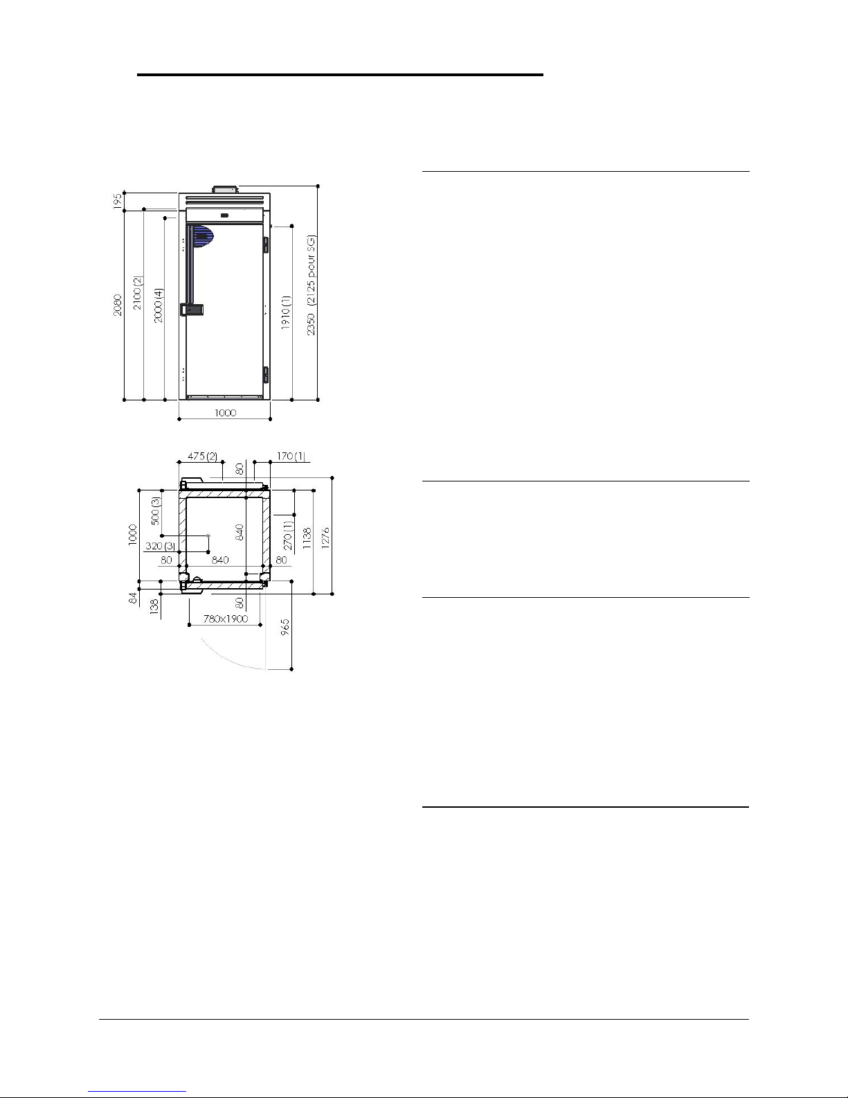
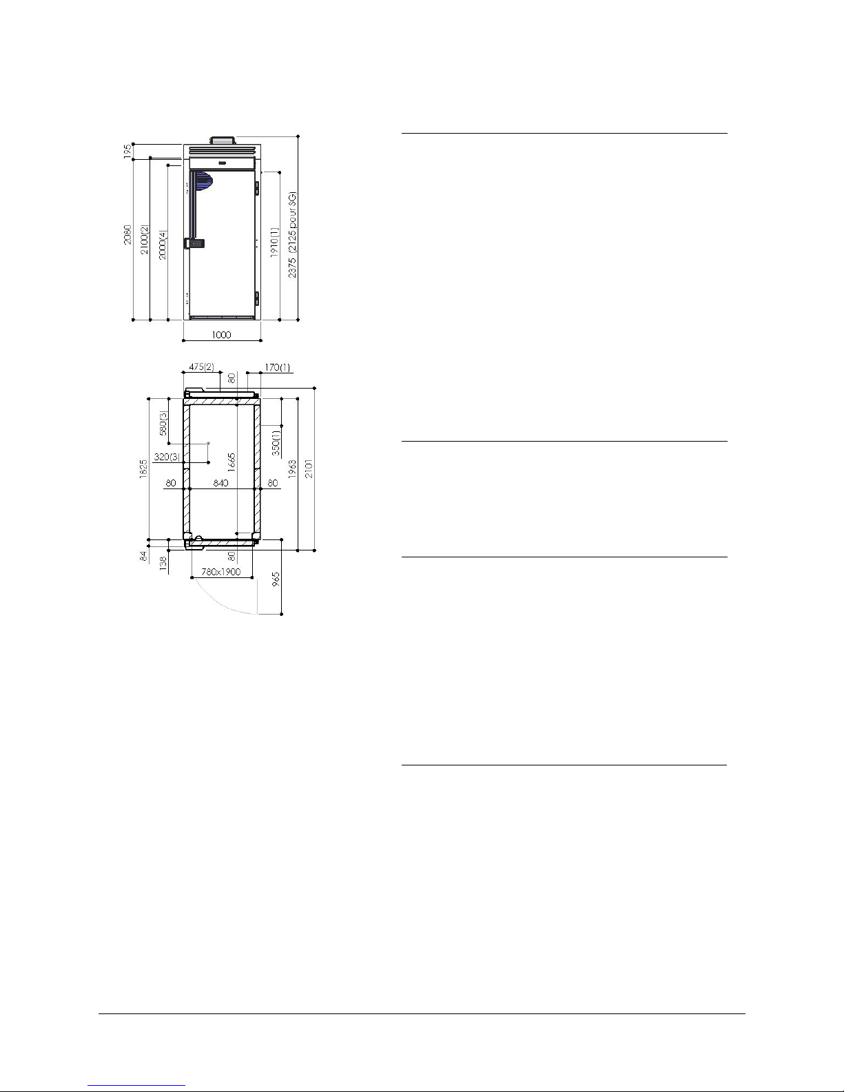
1.3 Model 3x1C
S200B31 : Model 3x1C Stainless 1D to RHS
S201B31 : Model 3x1C Stainless 1D to LHS
S202B31 : Model 3x1C Stainless 1D central
S210B31 : Model 3x1C White 1D to RHS
S211B31 : Model 3x1C White 1D to LHS
S212B31 : Model 3x1C White 1D central
Roll in model shown with 1 door to the right and clearance
for a rear door (roll through).
(1) Defrost water drain (PVC pipe ∅20)
(2) Electrical connection (supply cable 3m long)
(3) Refrigeration connection (SG version)
(4) Height under evaporator housing 1900mm
Note :
- With a glass door operating at +3°C, the temperature
and humidity conditions required for operation without
condensation are +25°C and 65% RH or equivalent
LOCATION
The cabinet must be installed on a flat, smooth and
perfectly horizontal surface. A bead of silicone mastic is
required around the perimeter.
CONSTRUCTION
- Internal and external panels in austenitic stainless or
white plastic coated steel (except the external roof in
corrosion proof galvanised sheet).
- Slatted louvered compressor cover (not supplied with
models without compressor).
Insulated body
- Demountable panels assembled by a system of hooks.
- Expanded polyurethane foam insulation. 80mm thick
- Thermal break between cavity and outer structure.
- Floor fixing strips in austenitic stainless steel.
- Radiused stainless base (optional).
Door
- Removable magnetic door seal with base blade
- 2 rising hinges with stay open position and self closure,
avoids wear on the door base seal.
- Closure by central lockable handle and catch with
internal push button safety release.
- Door opening can be handed (if undertaken on site
new lexan signage will be required)
ELECTRICAL CHARACTERISTICS
Voltage : 1~230V 50Hz+E
Max power : 1250W
Protection : aM 6
Unit supplied with a cable and plug
The installer is responsible for electrical protection of the
supply circuit
REFRIGERATION CHARACTERISTICS
Refrig power : 1200 W at -15/+55°C
Refrigerant : R404A
Charge : See units data plate
Compressor : Hermetic
Condenser : air cooled
Evaporator : Double flux ventilation, anti-corrosion
treated
Expansion : Capillary (model without compressor
supplied with T.E.V.)
Defrost water : Two drain points (1) are provided at the
rear or the right hand side (connection
and traps to be provided by the installer).
Conforms to norms :
Electrical safety : EN 60 335-1
Food hygiene : XP U 60 010
Conforms to European directives for : CE

n° 6BE648285NI-0606 – Page 5
1.4 Model 1x2C
S200B12 : Model 1x2C Stainless
S210B12 : Model 1x2C White
Roll in model shown with clearance for rear door
(roll through).
(1) Defrost water drain (PVC pipe ∅20)
(2) Electrical connection (supply cable 3m long)
(3) Refrigeration connection (SG version)
(4) Height under evaporator housing 1900mm
Note :
- With a glass door operating at +3°C, the
temperature and humidity conditions required for
operation without condensation are +25°C and
65% RH or equivalent
LOCATION
The cabinet must be installed on a flat, smooth and
perfectly horizontal surface. A bead of silicone mastic is
required around the perimeter.
CONSTRUCTION
- Internal and external panels in austenitic stainless or
white plastic coated steel (except the external roof in
corrosion proof galvanised sheet).
- Slatted louvered compressor cover (not supplied with
models without compressor).
Insulated body
- Demountable panels assembled by a system of hooks.
- Expanded polyurethane foam insulation. 80mm thick
- Thermal break between cavity and outer structure.
- Floor fixing strips in austenitic stainless steel.
- Radiused stainless base (optional).
Door
- Removable magnetic door seal with base blade
- 2 rising hinges with stay open position and self closure,
avoids wear on the door base seal.
- Closure by central lockable handle and catch with
internal push button safety release.
- Door opening can be handed (if undertaken on site
new lexan signage will be required)
ELECTRICAL CHARACTERISTICS
Voltage : 1~230V 50Hz+E
Max power : 1100W
Protection : aM 6
Unit supplied with a cable and plug
The installer is responsible for electrical protection of the
supply circuit
REFRIGERATION CHARACTERISTICS
Refrig power : 940 W at -15/+55°C
Refrigerant : R404A
Charge : See units data plate
Compressor : Hermetic
Condenser : air cooled
Evaporator : Double flux ventilation, anti-corrosion
treated
Expansion : Capillary (model without compressor
supplied with T.E.V.)
Defrost water : Two drain points (1) are provided at the
rear or the right hand side (connection
and traps to be provided by the installer).
Conforms to norms :
Electrical safety : EN 60 335-1
Food hygiene : XP U 60 010
Conforms to European directives for : CE

n° 6BE648285NI-0606 – Page 6
1.5 Model 2x2C
S200B22 : Model 2x2C Stainless 1D to RHS
S201B22 : Model 2x2C Stainless 1D to LHS
S210B22 : Model 2x2C White 1D to RHS
S211B22 : Model 2x2C White 1D to LHS
Roll in model shown with 1 door to the right and
clearance for a rear door (roll through).
(1) Defrost water drain (PVC pipe ∅20)
(2) Electrical connection (supply cable 3m long)
(3) Refrigeration connection (SG version)
(4) Height under evaporator housing 1900mm
Note :
- With a glass door operating at +3°C, the
temperature and humidity conditions required for
operation without condensation are +25°C and
65% RH or equivalent
LOCATION
The cabinet must be installed on a flat, smooth and
perfectly horizontal surface. A bead of silicone mastic is
required around the perimeter.
CONSTRUCTION
- Internal and external panels in austenitic stainless or
white plastic coated steel (except the external roof in
corrosion proof galvanised sheet).
- Slatted louvered compressor cover (not supplied with
models without compressor).
Insulated body
- Demountable panels assembled by a system of hooks.
- Expanded polyurethane foam insulation. 80mm thick
- Thermal break between cavity and outer structure.
- Floor fixing strips in austenitic stainless steel.
- Radiused stainless base (optional).
Door
- Removable magnetic door seal with base blade
- 2 rising hinges with stay open position and self closure,
avoids wear on the door base seal.
- Closure by central lockable handle and catch with
internal push button safety release.
- Door opening can be handed (if undertaken on site
new lexan signage will be required)
ELECTRICAL CHARACTERISTICS
Voltage : 1~230V 50Hz+E
Max power : 1400W
Protection : aM 8
Unit supplied with a cable and plug
The installer is responsible for electrical protection of the
supply circuit
REFRIGERATION CHARACTERISTICS
Refrig power : 1400 W at -15/+55°C
Refrigerant : R404A
Charge : See units data plate
Compressor : Hermetic
Condenser : air cooled
Evaporator : Double flux ventilation, anti-corrosion
treated
Expansion : T.E.V. (model without compressor
supplied with T.E.V.)
Defrost water : Two drain points (1) are provided at the
rear or the right hand side (connection
and traps to be provided by the installer).
Conforms to norms :
Electrical safety : EN 60 335-1
Food hygiene : XP U 60 010
Conforms to European directives for : CE

n° 6BE648285NI-0606 – Page 7
1.6 Model 3x2C
S200B32 : Model 3x2C Stainless 1D to RHS
S201B32 : Model 3x2C Stainless 1D to LHS
S202B32 : Model 3x2C Stainless 1D central
S210B32 : Model 3x2C White 1D to RHS
S211B32 : Model 3x2C White 1D to LHS
S212B32 : Model 3x2C White 1D central
Roll in model shown with 1 door to the right and
clearance for a rear door (roll through).
(1) Defrost water drain (PVC pipe ∅20)
(2) Electrical connection (supply cable 3m long)
(3) Refrigeration connection (SG version)
(4) Height under evaporator housing 1900mm
Note :
- With a glass door operating at +3°C, the temperature
and humidity conditions required for operation without
condensation are +25°C and 65% RH or equivalent
LOCATION
The cabinet must be installed on a flat, smooth and
perfectly horizontal surface. A bead of silicone mastic is
required around the perimeter.
CONSTRUCTION
- Internal and external panels in austenitic stainless or
white plastic coated steel (except the external roof in
corrosion proof galvanised sheet).
- Slatted louvered compressor cover (not supplied with
models without compressor).
Insulated body
- Demountable panels assembled by a system of hooks.
- Expanded polyurethane foam insulation. 80mm thick
- Thermal break between cavity and outer structure.
- Floor fixing strips in austenitic stainless steel.
- Radiused stainless base (optional).
Door
- Removable magnetic door seal with base blade
- 2 rising hinges with stay open position and self closure,
avoids wear on the door base seal.
- Closure by central lockable handle and catch with
internal push button safety release.
- Door opening can be handed (if undertaken on site
new lexan signage will be required)
ELECTRICAL CHARACTERISTICS
Voltage : 1~230V 50Hz+E
Max power : 1700W
Protection : aM 8
Unit supplied with a cable and plug
The installer is responsible for electrical protection of the
supply circuit
REFRIGERATION CHARACTERISTICS
Refrig power : 2000 W at -15/+55°C
Refrigerant : R404A
Charge : See units data plate
Compressor : Hermetic
Condenser : air cooled
Evaporator : Double flux ventilation, anti-corrosion
treated
Expansion : T.E.V. (model without compressor
supplied with T.E.V.)
Defrost water : Two drain points (1) are provided at the
rear or the right hand side (connection
and traps to be provided by the installer).
Conforms to norms :
Electrical safety : EN 60 335-1
Food hygiene : XP U 60 010
Conforms to European directives for : CE

n° 6BE648285NI-0606 – Page 8
1.7 Model 1x3C
S200B13 : Model 1x3C Stainless
S210B13 : Model 1x3C White
Roll in model shown with clearance for rear door
(roll through).
(1) Defrost water drain (PVC pipe ∅20)
(2) Electrical connection (supply cable 3m long)
(3) Refrigeration connection (SG version)
(4) Height under evaporator housing 1900mm
Note :
- With a glass door operating at +3°C, the
temperature and humidity conditions required for
operation without condensation are +25°C and
65% RH or equivalent
LOCATION
The cabinet must be installed on a flat, smooth and
perfectly horizontal surface. A bead of silicone mastic is
required around the perimeter.
CONSTRUCTION
- Internal and external panels in austenitic stainless or
white plastic coated steel (except the external roof in
corrosion proof galvanised sheet).
- Slatted louvered compressor cover (not supplied with
models without compressor).
Insulated body
- Demountable panels assembled by a system of hooks.
- Expanded polyurethane foam insulation. 80mm thick
- Thermal break between cavity and outer structure.
- Floor fixing strips in austenitic stainless steel.
- Radiused stainless base (optional).
Door
- Removable magnetic door seal with base blade
- 2 rising hinges with stay open position and self closure,
avoids wear on the door base seal.
- Closure by central lockable handle and catch with
internal push button safety release.
- Door opening can be handed (if undertaken on site
new lexan signage will be required)
ELECTRICAL CHARACTERISTICS
Voltage : 1~230V 50Hz+E
Max power : 1100W
Protection : aM 6
Unit supplied with a cable and plug
The installer is responsible for electrical protection of the
supply circuit
REFRIGERATION CHARACTERISTICS
Refrig power : 940 W at -15/+55°C
Refrigerant : R404A
Charge : See units data plate
Compressor : Hermetic
Condenser : air cooled
Evaporator : Double flux ventilation, anti-corrosion
treated
Expansion : Capillary (model without compressor
supplied with T.E.V.)
Defrost water : Two drain points (1) are provided at the
rear or the right hand side (connection
and traps to be provided by the installer).
Conforms to norms :
Electrical safety : EN 60 335-1
Food hygiene : XP U 60 010
Conforms to European directives for : CE

n° 6BE648285NI-0606 – Page 9
1.8 Model 2x3C
S200B23 : Model 2x3C Stainless 1D to RHS
S201B23 : Model 2x3C Stainless 1D to LHS
S210B23 : Model 2x3C White 1D to RHS
S211B23 : Model 2x3C White 1D to LHS
Roll in model shown with 1 door to the right and
clearance for a rear door (roll through).
.
(1) Defrost water drain (PVC pipe ∅20)
(2) Electrical connection (supply cable 3m long)
(3) Refrigeration connection (SG version)
(4) Height under evaporator housing 1900mm
Note :
- With a glass door operating at +3°C, the
temperature and humidity conditions required for
operation without condensation are +25°C and
65% RH or equivalent
LOCATION
The cabinet must be installed on a flat, smooth and
perfectly horizontal surface. A bead of silicone mastic is
required around the perimeter.
CONSTRUCTION
- Internal and external panels in austenitic stainless or
white plastic coated steel (except the external roof in
corrosion proof galvanised sheet).
- Slatted louvered compressor cover (not supplied with
models without compressor).
Insulated body
- Demountable panels assembled by a system of hooks.
- Expanded polyurethane foam insulation. 80mm thick
- Thermal break between cavity and outer structure.
- Floor fixing strips in austenitic stainless steel.
- Radiused stainless base (optional).
Door
- Removable magnetic door seal with base blade
- 2 rising hinges with stay open position and self closure,
avoids wear on the door base seal.
- Closure by central lockable handle and catch with
internal push button safety release.
- Door opening can be handed (if undertaken on site
new lexan signage will be required)
ELECTRICAL CHARACTERISTICS
Voltage : 1~230V 50Hz+E
Max power : 1700W
Protection : aM 8
Unit supplied with a cable and plug
The installer is responsible for electrical protection of the
supply circuit
REFRIGERATION CHARACTERISTICS
Refrig power : 2000 W at -15/+55°C
Refrigerant : R404A
Charge : See units data plate
Compressor : Hermetic
Condenser : air cooled
Evaporator : Double flux ventilation, anti-corrosion
treated
Expansion : T.E.V. (model without compressor
supplied with T.E.V.)
Defrost water : Two drain points (1) are provided at the
rear or the right hand side (connection
and traps to be provided by the installer).
Conforms to norms :
Electrical safety : EN 60 335-1
Food hygiene : XP U 60 010
Conforms to European directives for : CE

n° 6BE648285NI-0606 – Page 10
1.9 Model 3x3C
S200B33 : Model 3x3C Stainless 1D to RHS
S201B33 : Model 3x3C Stainless 1D to LHS
S202B33 : Model 3x3C Stainless 1D central
S210B33 : Model 3x3C White 1D to RHS
S211B33 : Model 3x3C White 1D to LHS
S212B33 : Model 3x3C White 1D central
Roll in model shown with 1 door to the right and
clearance for a rear door (roll through).
(1) Defrost water drain (PVC pipe ∅20)
(2) Electrical connection (supply cable 3m long)
(3) Refrigeration connection (SG version)
(4) Height under evaporator housing 1900mm
Note :
- With a glass door operating at +3°C, the temperature
and humidity conditions required for operation without
condensation are +25°C and 65% RH or equivalent
LOCATION
The cabinet must be installed on a flat, smooth and
perfectly horizontal surface. A bead of silicone mastic is
required around the perimeter.
CONSTRUCTION
- Internal and external panels in austenitic stainless or
white plastic coated steel (except the external roof in
corrosion proof galvanised sheet).
- Slatted louvered compressor cover (not supplied with
models without compressor).
Insulated body
- Demountable panels assembled by a system of hooks.
- Expanded polyurethane foam insulation. 80mm thick
- Thermal break between cavity and outer structure.
- Floor fixing strips in austenitic stainless steel.
- Radiused stainless base (optional).
Door
- Removable magnetic door seal with base blade
- 2 rising hinges with stay open position and self closure,
avoids wear on the door base seal.
- Closure by central lockable handle and catch with
internal push button safety release.
- Door opening can be handed (if undertaken on site
new lexan signage will be required)
ELECTRICAL CHARACTERISTICS
Voltage : 1~230V 50Hz+E
Max power : 2100W
Protection : aM 10
Unit supplied with a cable and plug
The installer is responsible for electrical protection of the
supply circuit
REFRIGERATION CHARACTERISTICS
Refrig power : 2500 W at -15/+55°C
Refrigerant : R404A
Charge : See units data plate
Compressor : Hermetic
Condenser : air cooled
Evaporator : Double flux ventilation, anti-corrosion
treated
Expansion : T.E.V. (model without compressor
supplied with T.E.V.)
Defrost water : Two drain points (1) are provided at the
rear or the right hand side (connection
and traps to be provided by the installer).
Conforms to norms :
Electrical safety : EN 60 335-1
Food hygiene : XP U 60 010
Conforms to European directives for : CE

n° 6BE648285NI-0606 – Page 11
2. DATA PLATE
The data plate is to be found fixed to the refrigeration platform.
For all correspondence relating to your equipment remember :
- The unit code (Type)
- The serial number (N° SERIE)
- The date (Date)
The principal characteristics are repeated on a label fixed to:
- The left hand internal panel
- The certificate of CE conformity supplied with the unit.
Voir plaque pour cellules et Arm chaudes

n° 6BE648285NI-0606 – Page 12
3. INSTALLATION
3.1 GENERAL REQUIREMENTS
The installation, any repairs or alterations to this equipment should be undertaken by
qualified specialists.
3.2 HANDLING
The appliance should be moved with specialist lifting gear.
If the unit must be transported it should be on its original pallet and should under no
circumstances be stacked.
3.3 UNPACKING AND LOCATING
3.3.1 UNPACKING
After cutting the banding lift the parts off and identify them from the packing note.
The refrigerated platform is delivered pre connected to the control panel.
3.3.2 LOCATING
Once a location has been chosen ensure that the air around the unit is sufficient to
provide adequate cooling to the condenser and compressor
Allow a 5 to 10cm clearance around the unit.
Avoid proximity to any heat source.
Model shown: 2x1C GI cabinet with 2 doors
Refrigerated platform
Box or accessories
Door frame and doo
r
Back panels
Side panels
Control panel
Wooden pallet

n° 6BE648285NI-0606 – Page 13
3.4 ASSEMBLY INSTRUCTIONS
3.4.1 ASSEMBLY PRINCIPLES
Model shown: 2x1C GI cabinet with 2 doors to the front.
Note :
Depending on the model (roll through for example) the back panels may be replaced with
equivalent doors and frames and vice versa.
The rear panel or door frame is located between two side panels on 3 trolley models and
over.
The additional dimensions of tunnel models extend the basic sizes of standard units.
Compressor cover
assembly (GI model only)
Refrigeration platform
Control panel
End panel
Right rea
r
End panel
Left rea
r
Left hand door &
frame
Right hand door &
frame
Floor fixing channel
Door frame fixing bracket

n° 6BE648285NI-0606 – Page 14
3.4.2 FLOOR FIXING CHANNEL
IMPORTANT : The floor fixing channels should be fixed to a perfectly flat and horizontal
floor.
With the stainless base option the channels are replaced by a radiused stainless sheet.
In this case, to avoid water infiltration the base should be sealed to the floor with mastic
particularly in the doorways.
1) Start by marking out the location on the floor following the diagram below :
2) Fix the channels to one another with the angle connections code 683530X then bolt
to the floor (floor fixings provided by the installer, M5 shot fired are recommended)
Model shown: 2x1C GI cabinet with 2 doors to the front
Door frame bracket
683530Y
Angle connection
683530X
Rear channels
683530A (U Lg.825)
683530B (D Lg.913)
683530B (G Lg.913)
683530B (M Lg.1000)
Side channels
683530A (1C Lg.825)
683530E (2C Lg.1650)
683530F (3C Lg.2475)

n° 6BE648285NI-0606 – Page 15
3.4.3 INSTALLING THE PANELS
Assemble the panels so that the 8mm locating pegs fit into the locking boxes . Locking
is accomplished using a special key provided with the unit, simply turn until it engages. The
holes are plugged by 10mm covers that are supplied.
1) Start by assembling the back and corner panels
2) Position the refrigeration platform (without
locking it in place)
3) Assemble the front panel (door frame
and door)
Lock all the remaining fittings.
Finish by fixing the door frame bracket.
Angled lock key
Locating pegs
∅
8Hole plug
∅
10
Locating pegs∅8
1
2
2
1

n° 6BE648285NI-0606 – Page 16
3.4.4 FITTING THE CONTROL PANEL
1) Start by outlining the location and drilling
the 3mm holes.
2) Open the facia and fit the back of the
control panel with 4 self tapping screws
3.4.5 FITTING THE COMPRESSOR COVER (for GI models)
Fix the different pieces of the front cover on to the top of the side panels (where the
factory has drilled holes) using the n°8-19 self tapping screws supplied.
Across the width each join in the facia has an angled reinforcement.
Depending on the model (eg roll through) the corner angles are replaced by full panels.
4 self tapping screws
control panel
Facia
Model shown: 2x1C GI cabinet with 2 doors to the front control panel to the right
Facia for control panel
675243 (Single)
675244 (Right)
675245 (Left)
675246 (Central)
Facia without control panel
675247 (Single)
675248 (Right)
675249 (Left)
675250
(
Central
)
Sides
675242
Angle
675241
Sides
675242
Angle
675241
Angled stiffener
675240 M5 nut
M5
p
an head
Self tapper CB n°8-19

n° 6BE648285NI-0606 – Page 17
3.4.6 FITTING THE FLOOR FINISHING KITS (optional)
After cutting them to length, the PVC finishing strips are fixed to the cabinet using the
FB n°4.19 self tapping screws provided. Seal in place with silicone mastic.
Internal finishing strips are not compatible with the stainless floor base option.
3.4.7 REVERSING THE DOOR HANDING
On site this operation requires that a set of lexan labels be ordered.
1) After disengaging the door, swap the hinges and door catch fitted to the door frame
from right to left or vice versa.
2) Unscrew the part of the hinges fitted to the door and refit in the same place having
turned them upside down.
3) Swap the bottom door seal blade and the top light actuator positions over.
4) Remove the door labels and replace with new. Surplus glue can be removed with
thinners.
If the door doesn’t line up adjustment can be made using the 1.5mm PVC spacers
factory fitted behind each hinge.
Example: To realign a door that has dropped, remove a spacer from the upper hinge
and add to the lower hinge.
Model shown: Single door frame with right hand door
Li
g
ht actuato
r
Door seal blade
240x210 Label
code S380P11 : With controls over
code S381P11 : No controls over
65x865
code S417P11 : With controls over
code S418P11 : No controls over
Brand label
code S110P02
Hin
g
e on door frame
Door catch
Door hin
g
e
1.5mm thick hin
g
e s
p
acers

n° 6BE648285NI-0606 – Page 18
3.5 CONNECTIONS (See § 1 "Technical characteristics")
3.5.1 REFRIGERATION
Cabinets that are not fully equipped (without compressor) are supplied with an external
suction tube and a thermostatic expansion valve on top of the unit.
3.5.2 ELECTRICS
The unit is fitted with a supply cable which should not be removed.
Earth continuity must be maintained (see § Important recommendations).
Provision of a circuit breaker or fuses to protect the supply is the responsibility of the
installer.
3.5.2 DEFROST WATER
Depending on the model (roll in or roll through) the cabinet is supplied with a drain kit for
rear or side exit
The kit supplied allows the evaporation drain tray to be piped to waste through a 20mm
dia. hole, 1910mm from the floor, in the rear or side of the cabinet using PVC ∅20 tube.
Connection to drain (at the installers cost) must be via an air break to prevent any back
siphonage.
Rear exit Side exit
Optional defrost re-evaporation container
Position shown: right hand side
Electrical connection box
Water outlet
Element cove
r
Plastic containe
r
Element
Tra
p
Drainer tra
y
Sleeve
PVC tube ∅20
PVC elbo
w
PVC tube ∅20
Drainer tra
y
This manual suits for next models
34
Table of contents
Other Bonnet Freezer manuals
Popular Freezer manuals by other brands

Electrolux
Electrolux ECN 1155 OPERATING AND INSTALLATION Manual

Frigidaire
Frigidaire Freezer P/N 297079200 use and care manual

Zanussi
Zanussi easyChill BCFWS101 110712 Specifications

Sharp
Sharp SJ-BA05DHXLF-EU user manual

Stoelting
Stoelting F112 owner's manual

Electrolux
Electrolux Onyx 125 FA Instruction book