Boreal ACDX-45 User manual

2005 Boreal Geothermal Inc. www.boreal-geothermal.com
Installation
Manual
ACDX 45-55-65
High Efficiency Direct Expansion
Geothermal Heat Pumps
Energy Efficient Solutions
Tel : 514 – 886 – 0682
Web : www.boreal-geothermal.com
Boreal GEOTHERMAL Inc.

2
2005 Boreal Geothermal Inc. www.boreal-geothermal.com
WARNING!
WARNING! Verify refrigerant before proceeding. Units are
shipped with a R22 or a R410A refrigerant. The unit label
will indicate which refrigerant is provided.
WARNING!
WARNING! To avoid the release of refrigerant into the
atmosphere, the refrigerant circuit of this unit must be
serviced only by technicians who meet local, state and
federal proficiency requirements.
WARNING!
WARNING! All refrigerant discharged from this unit must
be recovered WITHOUT EXCEPTION. Technicians must
follow industry accepted guidelines and all local, state and
federal statutes for the recovery and disposal of refrigerants,
If a compressor is removed from this unit, refrigerant circuit
oil will remain in the compressor. To avoid leakage of the
compressor oil, refrigerant lines of the compressor must be
sealed after it is removed.
CAUTION!
CAUTION! To avoid equipment damage, DO NOT use
these units as a source of heating or cooling during the con-
struction process. The mechanical components and filters
will quickly become clogged with construction dirt and de-
bris, which may cause system damage.

3
2005 Boreal Geothermal Inc. www.boreal-geothermal.com
Table of Contents
• Heat Pump System Requirements 3
• Optimum Placement 7
• Installing ACDX line sets 9
• Vacuuming & Charging 11
• Built-in refrigerant safety controls 13
• Theory of Operation 15
• Vertical Case Dimensions 18
• Horizontal Dimensions 19
20
• Electrical Requirements
• Component Layout 21
• Performance Ratings 22
• CFM available 23
• Trouble Shooting Guide 24
• Electrical Schematic 27
• Installer Wiring 28
• Plenum Heater Wiring 29
• Duct sizing Guide 30
• Warranty 35
Section Page
• Electronic Control Board 31

4
2005 Boreal Geothermal Inc. www.boreal-geothermal.com
Boreal® ACDX Heat Pump System Prerequisites
There are 4 (four) specific parts or sub systems to a ACDX heat pump installation:
I. The source of energy Solar & Geothermal
II. The storage media The Earth’s mass
III. Converting the energy to a useable form Heat Pump
IV. Distributing the heat Ductwork / radiant slab
Horizontal Loop Fields
The successful application of a ACDX heat
pump depends on sizing the machine correctly for
the home or area to condition and providing enough
land area or volume of earth from which to extract
or reject heat.
ACDX heat pumps react with the earth much
like a conventional reversing heat pump and
closed loop plastic earth heat exchanger. Heat
that is available to the unit must travel through the
earth and therefore the conduction capability of the
earth in the location of the heat exchanger is very
important. A unit used entirely or primarily for
heating will have no problem with conduction and
heat transfer since it will be cooling the loop during
heating mode which draws moisture towards the
coils because they are colder than the surrounding
ground. Horizontal loop fields should be laid out so
that the copper coils have good cross-sectional in-
fluence on the minimum areas listed above. As a
general rule, wider spacing between the loops so
that they do not influence one another, will result in
improved performance of the heat pump.
Unless you are sure there will be sufficient
moisture present in the loop field area during the
summer, a soaker hose is recommended in all hori-
zontal trench systems which will used for air condi-
tioning purposes.
Vertical Bore Systems
Vertical bores (3” x 100 ft. holes) provide an
alternate method of installing a ACDX unit. A high
water table in the borehole area (20 to 30 ft.) will
insure that there is adequate conduction with the
earth and although the loop length per ton is shorter
than the horizontal design, the vertical orientation
and moisture in the boreholes provides very uni-
form conduction both winter and summer.
Air Flow
The charts above and below are general guide-
lines in selecting a ACDX-to-Air heat pump for
residential application. A detailed heat loss analysis
should be performed to determine the actual loads
on the building and to assist in sizing ductwork for
each individual room or space in the building.
Model Number of
Loops Required
Area Trench
Layout
Boreal ACDX-45 (3) x 350’ 8,000 ft² 4’x 175’
Boreal ACDX-55 (4) x 350’ 10,000 ft² 4’ x 175’
Boreal ACDX-65 (5) x 350’ 12,500 ft² 4’ x 175’
Note: These are minimum loop field requirements based on an
earth temperature of 45° F.
Boreal® ACDX-45 will heat up to 1500 sq. ft.
Boreal® ACDX-55 will heat up to 2000 sq. ft.
Boreal® ACDX-65 will heat up to 2500 sq. ft.
Assuming at least R-20 walls and R-40 ceiling
Boreal® ACDX-45 models 1600 cfm
Boreal® ACDX-55 models 1900 cfm
Boreal® ACDX-65 models 2100 cfm
@ 80°F DB / 67°F WB and static pres of .2” H20
Air Flow Available from each heat pump
Boreal® ACDX-45 could have up to 16 hot air grills.
Boreal® ACDX-55 could have up to 19 hot air grills.
Boreal® ACDX-65 could have up to 21 hot air grills.

5
2005 Boreal Geothermal Inc. www.boreal-geothermal.com
BOREAL® “ACDX” Series — Plumbing and Ductwork
NOTE:
If (2) valves are installed on the hot water lines as shown
in this diagram then a pressure relief valve (set at 75 - 100
psig.) must also be installed to prevent the build-up of
pressure which may result in bursting of the circulator
pump housing if the unit is operated while both valves are
shut.
(See point “A” marked above)
Boreal® ACDX (All Models)
♦ Hot water lines are 1/2” ID copper.
♦ Insulate both hot lines and all refrigerant lines.
♦ Use ball or gate valves on hot water lines.
♦ Set hot water thermostats in tank to 120°F.
♦ Use flexible duct collars to eliminate vibration and noise.

6
2005 Boreal Geothermal Inc. www.boreal-geothermal.com
Introduction to “ACDX” Technology
Direct earth coupled heat pump or “ACDX” heat pump is
one that has its refrigerant evaporator / condenser in direct ther-
mal contact with the earth from which heat is either extracted
from during the heating mode or introduced to during the cool-
ing mode of operation.
The general refrigeration cycle of our ACDX machine is
similar in nature to a conventional water-to-air or water-to-
water heat pump in that there exist a compressor, expansion
device, reversing valve, and refrigerant-to-air heat exchanger.
Conventional technology concerned with heat pumps relies
upon the transfer of heat from the ground by means of a secon-
dary heat exchanger system and working fluid, e.g., water,
which is pumped to the geothermal unit located in the heated
structure. The conventional heat pump has it’s own internal
primary heat exchanger which extracts heat (heating mode) or
rejects heat (cooling mode) from this water, which is then
pumped back to the earth to be reheated or cooled.
ACDX systems similarly use a ground coil system, how-
ever, the working fluid is a refrigerant and the copper ground
loop is the primary heat exchanger. Such geothermal heat ex-
change is an efficient and effective way of achieving heat ex-
change in heating and air conditioning systems, and especially
heat pump type systems. Since the ground temperature is rela-
tively constant at 48oF at a depth 6 ft. below the frost line, the
available heat is constant.
The elimination of the secondary earth heat exchanger
(typically plastic in nature) and its associated working fluid
reduces the temperature difference required between the ground
and the evaporating refrigerant yielding a higher suction pres-
sure than a conventional system under similar circumstances
and thus a higher efficiency.
Many attempts have been made in the past to develop suc-
cessful direct coupled heat pumps for residential and commer-
cial uses. These attempts have failed adequately to meet a num-
ber of requirements associated with an economically and func-
tionally viable system. Some of the shortcomings included:
I. Inadequate oil return to the compressor primarily in the
heating mode.
II. Inadequate evaporator length and spacing for properly ex-
tracting heat from the earth resulting in low capacity and
low efficiency of the systems.
III. Refrigerant charges in the range of 10 times greater than a
similar capacity conventional geothermal heat pump.
IV. Approximately 3 times as much refrigerant required in the
cooling mode as is required in the heating mode.
V. Lack of a proper means to store additional refrigerant re-
quired during the cooling operation but not needed during
the heating mode.
VI. Inefficient and ineffective method to account for vastly
varying condenser capability depending on ground tem-
perature.
VII.Difficulty in providing an easy to install system of earth
exchanger loops.
The BOREAL® solution has been to start with a clean
new concept and to design a unit from the ground up. We
started by developing an evaporator system that would yield
the best performance to pressure drop factor and which
would impact enough area to maintain a minimum suction
pressure above 40 Psig. The current horizontal ground loop
comprises 350 ft. per ton of 1/2” OD copper tubing. A 3 ton
system would have 3 such loops working in parallel during
the heating mode. Refrigerant charge had been determined
to be 5 lbs. of R-22 per loop. These 1/2” copper loops main-
tain sufficient velocity at all times to insure adequate oil
return. During cooling mode the machine automatically se-
lects one or more loops based on discharge pressure to act as
the condenser. As the discharge pressure builds to a prede-
termined point, the on-board computer selects the most ap-
propriate combination of ground loops to dissipate the heat
at the lowest cost to the homeowner. By intelligently con-
trolling the manner in which the condenser is utilized our
total system charge does not have to be altered nor does an
excess charge have to be stored anywhere.

7
2005 Boreal Geothermal Inc. www.boreal-geothermal.com
BOREAL® Vertical Style ACDX — Typical Loop design
Attention!
Layout for one borehole shown below.
Actual installation requires one borehole
per ton. (I.E. (3) holes for a ACDX-45,
(4) holes for a ACDX-55 and (5) for a
ACDX-65
Maximum 120 ft.
6 ft.
Pinch around pipes
and silver braze.
Keep pipes up 1/2”
off bottom to insure
good flow.
7/8” Stub Cap (Copper)
Boreal ® ACDX-to-Air
or
ACDX-to-Water Heat
Insulate liquid line
to here
Spacers
Liquid Line
Vapor Line Trench
Notes:
⇒ Drill vertical bore to a depth of 100 to 120 ft.
⇒ Pre-assemble or construct on site the dual (3/8” and 1/2”) piping as-
sembly required. Seal both ends and pressurize with 150 psig. nitrogen
for leak checking. Silver brazing a schrader valve in the end of the 3/8”
line will allow gauge checking for loss of pressure.
⇒ Check for leaks with soap suds. After a minimum 2 hr waiting period,
recheck the line for loss of pressure. If the temperature of the loop
hasn’t changed then the pressure should be same as it was originally.
⇒ Insulate both liquid lines and vapor lines from the heat pump to the
well head unless in separate horizontal trenches. Vapor lines in separate
horizontal trenches need only be insulated from 10 ft. out in the trench
to the basement wall. Liquid lines must be insulated from the heat
pump to approx. 6 ft. down the drop pipes in the vertical boreholes.
⇒ Install spacers to keep the pipes separated as far as possible from one
another in the boreholes.
⇒ Install 100 - 120 ft. of dual tubing (1/2” vapor & 3/8” liquid). Recheck
pressure on lines. Secure pipes through opening in borehole head.
Backfill with pea gravel to 30ft. from top. Seal hole with bentonite
clay from 30 ft. to surface.
⇒ Install linesets from well heads in horizontal trenches to heat pump in
building. Silver braze all joints with 5% silver solder using dry nitrogen
to purge the system. When all joints are complete, pressurize the entire
system with 150 psig. nitrogen and recheck for leaks. Vacuum until
system stays below 500 microns for five minuites after vacuum pump
has been shut off.
⇒ Charge the prescribed amount of refrigerant through the high side
schrader valve located on the front of the machine.

8
2005 Boreal Geothermal Inc. www.boreal-geothermal.com
BOREAL® ACDX Heat Pump
Installation Instructions
Unpacking
When the heat pump reaches it's destination it should be
unpacked to determine if any damage has occurred during
shipment. Any visible damage should be noted on the carrier's
freight bill and a suitable claim filed at once.
The heat pump is strongly constructed and every effort has
been made to insure that it will arrive intact, however, it is in
the customer's best interest to examine the unit thoroughly
when it arrives.
Optimum Placement
The BOREAL® heat pump has an air-filter rack which
can be removed for easy entry through a doorway or to facili-
tate moving the unit with a furniture cart. Simply remove the
two screws which hold the end cap in place, slide the cap off
and push the rack back off it's rails. When the heat pump is in
place the filter rack can be reinstalled with the removable end
(where the filter is removed) facing the direction that allows
easiest access for changing the filter.
To achieve the greatest efficiency, the heat pump should be
centrally located in the home with respect to the conditioned
space. This design provides the utmost in economy and com-
fort and usually can be accomplished in harmony with the
design of the home. A heating system cannot be expected to
produce an even warmth throughout the household when it is
located at one end of the structure and the warm air is trans-
mitted with uninsulated metal ductwork.
If possible the three main service doors should remain
clear of obstruction for a distance of (2) two ft. so that servic-
ing and general maintenance can be carried out with a mini-
mum of difficulty. Raising the heat pump off the floor a few
inches is generally a good practice since this will prevent un-
necessary rusting of the bottom panel of the unit.
We recommend that the heat pump be placed on a piece of
2" styrofoam covered with 1/4" plywood. The styrofoam will
smooth out any irregularities in the cement floor while the
plywood will distribute the weight of the BOREAL® unit
evenly over the styrofoam. This process will also deaden the
compressor noise emitted from the bottom of the cabinet.
As an alternative, several pieces of 2" x 4" lumber can be
placed under the unit running from the electrical connection
side to the filter rack side of the heat pump. Laying the 2" x
4"'s in this manner will give the best support since they will
be at right angles with the internal steel compressor and heat
exchanger supports.
Materials supplied by BOREAL®
BOREAL® supplies the ACDX heat pump with all inter-
nal valving and headering preassembled, pressure tested and
ready to be installed to the customers duct system and under-
ground copper exchanger loops. The underground coil assem-
blies are also supplied pre-tested and sealed with 100 psig.
nitrogen pressure. A ACDX system may comprise from 2 to 5
underground loops. One loop is required for each nominal
"ton" of compressor capacity. The standard loops are 1/2" OD
type “L” or “K” copper tubing. When the dealer unpacks the
coils the integrity of the loops can easily be checked by at-
taching a suitable pressure gauge to the 1/4" schrader valve on
the coil assembly. The pressure read at room temperature
should be approx. 100 psig. (+- 5 psig.) If a loop is not within
this tolerance, it should be set aside for retesting or returned
to BOREAL® for replacement. Under no circumstances
should a copper ground loop be used if there is any question
that it may not be pressure tight.
The ACDX heat pump unit has been high pressure tested
for leaks and has a holding charge of 30 psig. (nitrogen) when
the dealer receives it.
Materials you will need (inside)
A lineset is required to connect the heat pump to the under-
ground coils which will be installed outside the structure. This
lineset consists of one 3/8" liquid line and one 1/2" gas line
for each "ton" or loop installed. The dealer will be required to
silver braze (5% silfos) the required indoor linesets from the
point of entry to the basement or installation area to the heat
pump.

9
2005 Boreal Geothermal Inc. www.boreal-geothermal.com
Piping Layout of a BOREAL® Vertical ACDX Heat Pump System

10
2005 Boreal Geothermal Inc. www.boreal-geothermal.com
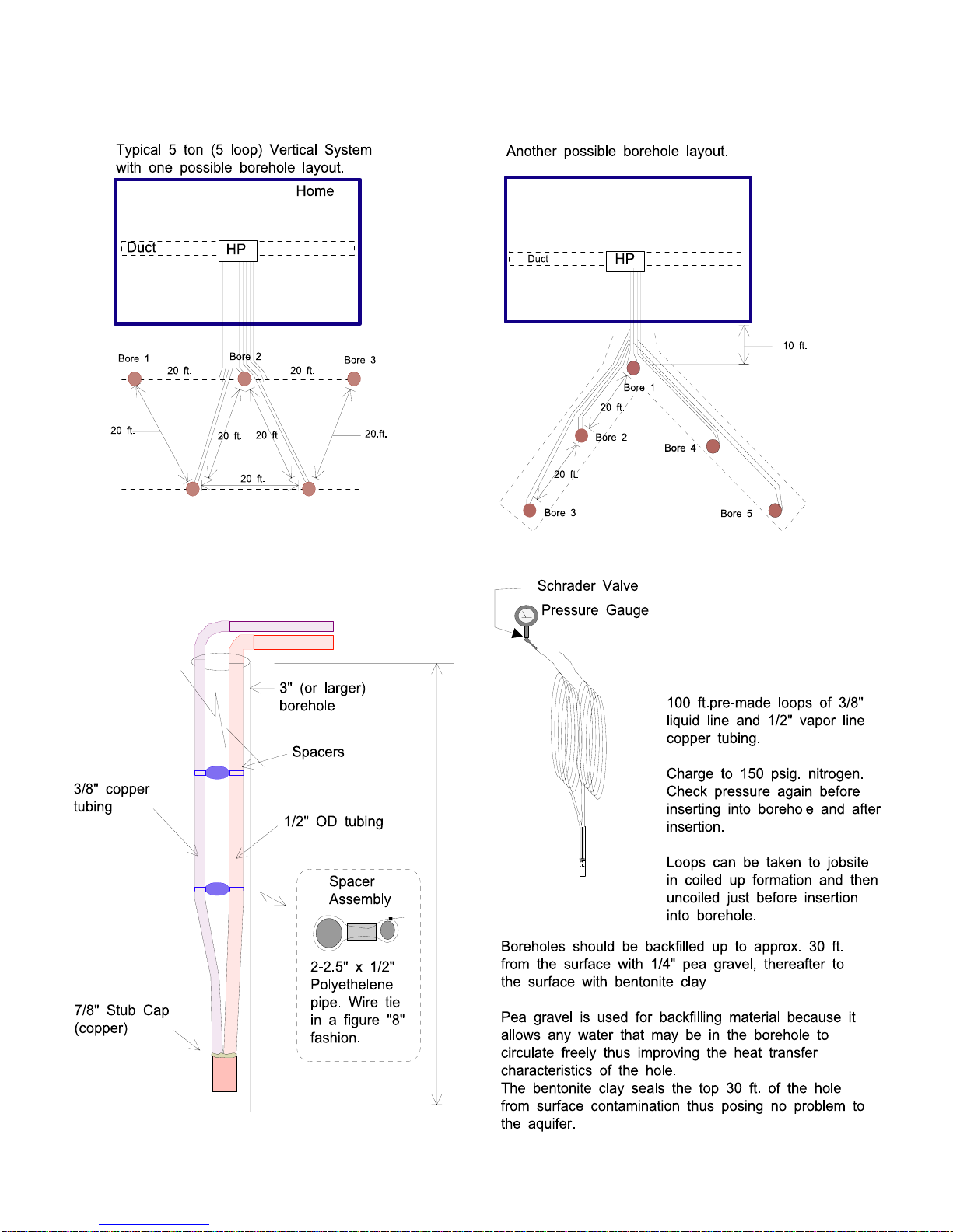
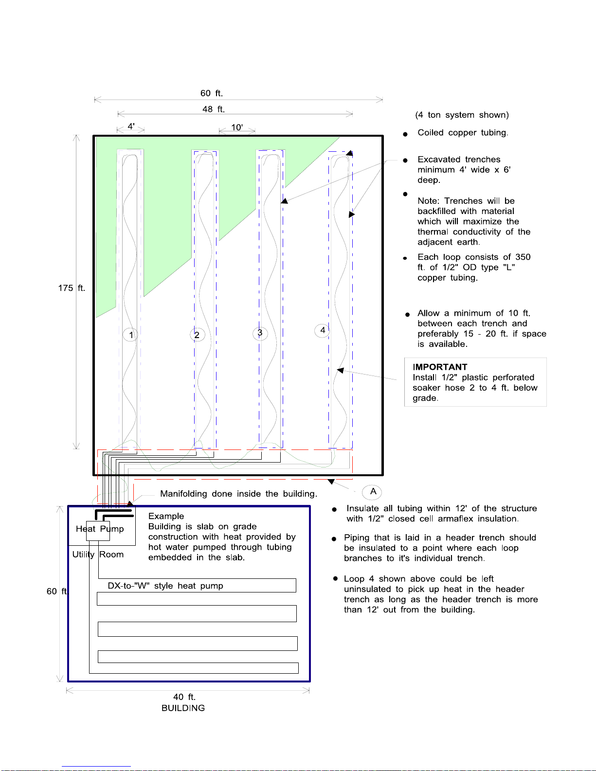
Horizontal Trench Requirements
The ACDX heat pump requires one groundcoil or "loop"
per nominal ton of capacity.
Trenching for the ACDX heat pump can be best accom-
plished with a tracked excavator equipped with a 44” to 48”
bucket. If a wider bucket is available and you can afford the
extra cost, the trenches could be wider for improved perform-
ance. The object, of course, is to allow the copper loops to
contact earth which has not been influenced by the prox-
imity of another loop. The trenches are dug from 5 to 6 ft.
deep to a total length of 180'. Each of the ACDX loops is
350' long and when laid in the form of a U down each side of
the trench the turn at the end will occur at 175' allowing for a
small degree of error by the excavator operator. Take special
care that the bottom of the trench is kept as smooth as possi-
ble to reduce the chance of pinching or crushing the copper
tubing when backfilling the trench. If rocky conditions are
encountered it is recommended that the bottom of the trench,
especially the corners where the pipe will lay, be covered by
hand with limestone tailings, or some other heavy dense ma-
terial t provide a relatively smooth resting place for the cop-
per pipe. Unlike plastic pipe, the copper tubing will stay
where you put it when unrolled rather than arguing with you,
as plastic does, on a cool day. Once the pipe has been un-
rolled and placed, backfilling by hand to a depth of 4-6" with
fill as described above will ensure that the pipe is protected
from falling rock etc. during the machine backfilling proce-
dure.
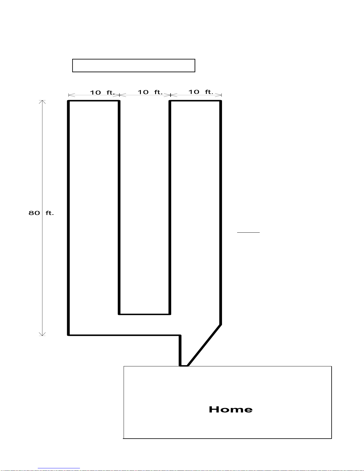
Other excavating devices such as a ditch-witch (chain
digger) or a regular back-hoe can be used if ground conditions
permit however you will have to dig a U shaped trench with
spacing 5 ft. to 10 ft.. We have found that the greater speed
of the tracked excavator in most soil conditions and the fact
that you only have to dig one trench (which is excellent width
for a man to work in) more than compensates for it's extra
rental or operational costs.
An alternative technique for burying the underground cop-
per tubing would be to dig a large shallow pit with a bull-
dozer. This pit would have to be large enough to accommo-
date all the loops required in the system. The copper tubes
should have a spacing of at least 6 ft. minimum. A wider
spacing would lead to slightly greater efficiency.
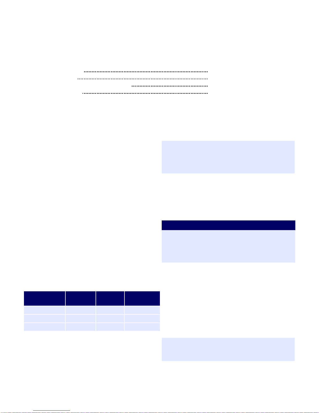
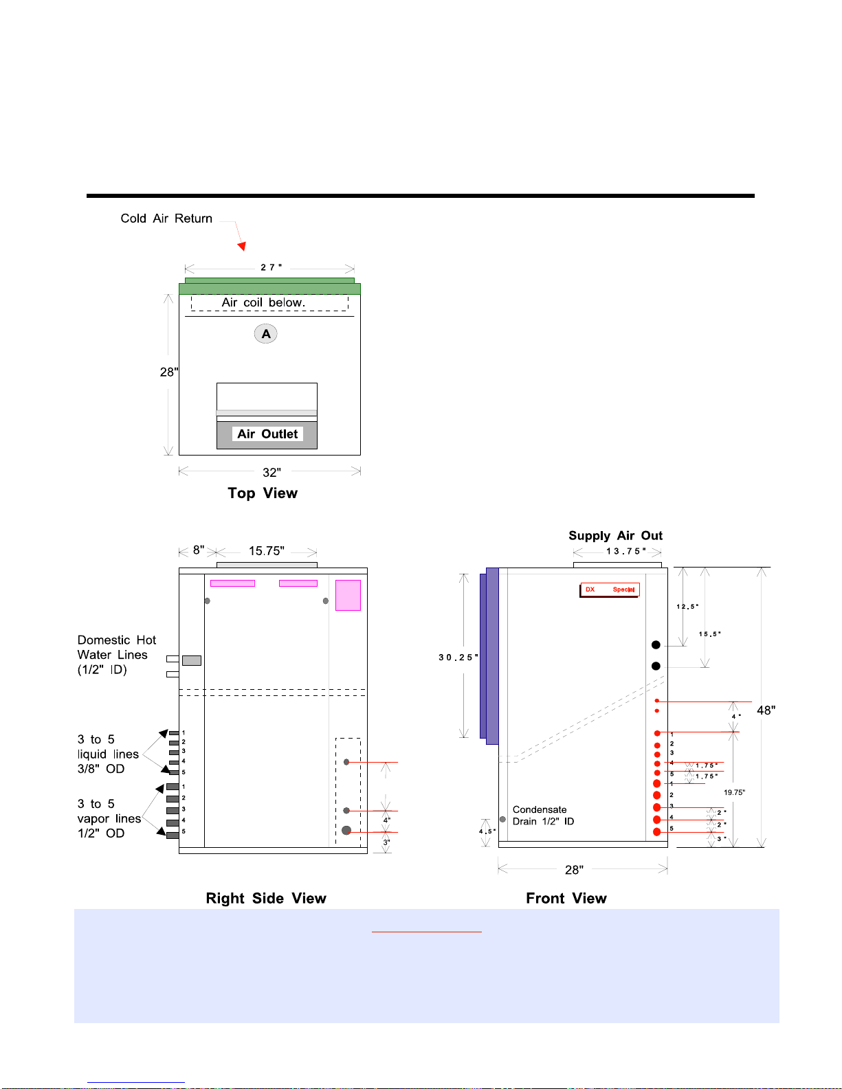
Entering dwelling
The copper ground loops must enter the dwelling at some
location typically through the concrete foundation just above
the poured floor. An alternate method would be to run the
pipe (insulated) up the outside wall making a 90 degree turn
above ground and entering the dwelling between the floor
joists just below the first floor. These pipes should be insu-
lated with a minimum of 3/4" of closed cell weatherproof
insulation. There will be two 1/2" OD copper tubes for each
nominal ton of capacity of the heat pump being installed. For
example a 3-ton unit would have 3 groundloops and thus 6
ends to go through the concrete wall. We recommend that you
drill these holes to a diameter large enough to allow for the
insertion of a plastic sleeve, (see drawing ) and the tubing
with it's insulation jacket. Suitable measures must be taken to
seal the installation from water penetration before the trench
is backfilled.
Unrolling & placing the Tubing
Each 50' roll of tubing is taped both individually and to
the next roll in the group so that at any one time only 50' of
the 350' is free to unroll. This allows for easier unrolling and
prevents kinking the pipe. Observe how the taping is done so
that you know which side of the loop to start unrolling first.
To begin, unroll approximately 12' of copper tubing. Slide
two 6' lengths of armaflex closed cell insulation with wall
thickness of at least 1/2”over the end of the tubing and insert
it through the plastic sleeve of hole # 1 approximately 8" into
the basement. It is good practice to label this line "loop 1 -
gas" to identify it when interconnecting linesets inside the
building. Unroll the copper tubing down one corner of the
trench. When 175 ft of tubing has been laid out make your
turn and proceed back the other side of the trench to the foun-
dation of the building. Slide two 6' lengths of armaflex insula-
tion onto the tubing and insert the stub end through hole # 2 in
the wall to match the other end of the loop. Label this end of
the line "loop 1 - liquid" so that the complete loop can be
identified later. Manually backfill the loop with fill to a depth
of 4 to 6" for protection during the machine backfill process.
Duplicate the process described above applying labels to
identify the two ends of successive loops (loop 2,3,4 etc.)
until all required loops are in place.
Insulation placement near foundation
It is important to apply closed cell insulation to the copper
ground loops as they come within 12' of the building to pre-
vent the possible build up of ice near the foundation of the
home. Applying 1/2” wall closed cell waterproof insulation to
the tubing as described above will insure that very little heat
is absorbed from the ground near the basement wall thus
avoiding possible frost damage to the structure.
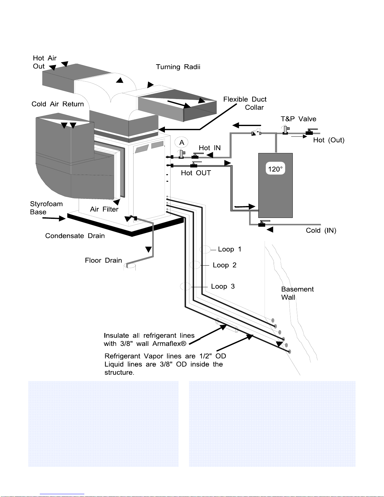
Pressure testing linesets
Using the 1/4" schrader valve supplied on each loop the
installer can again check the pressure on each lineset with his
refrigeration gauge set before releasing the pressure and cut-
ting the loop stubs coming into the basement to the proper
lengths.

11
2005 Boreal Geothermal Inc. www.boreal-geothermal.com
BOREAL® ACDX Horizontal Trench Design

12
2005 Boreal Geothermal Inc. www.boreal-geothermal.com
Interconnecting tubing
Once the outside loops have been installed it is necessary
to interconnect the "gas" and liquid lines of each loop coming
into the building to its corresponding line on the heat pump.
Each set of two pipes is labeled on the ACDX heat pump as
"loop 1 liquid"," loop 1 vapor", etc. depending on the tonnage
of the heat pump. The larger of the two pipes is the "gas" line
(1/2" OD) while the smaller line is the "liquid" line (3/8"
OD).
The dealer must install a 1/2" OD "gas" line from each of
the gas lines on the heat pump to the corresponding gas lines
of each ground loop. Similarly a 3/8" OD "liquid" line must
be run from each heat pump "liquid" line to the corresponding
liquid line of each ground loop.
Note that there is a transition in size from 3/8" to 1/2" as
the liquid line attaches to the ground loop stub coming into
the basement. A suitable reducing coupling can be purchased
from any refrigeration wholesaler.
The tubing used for this procedure must be refrigeration
tubing (cleaned & dehydrated) suitable for the job. Every ef-
fort must also be made to insure that the tubing does not be-
come contaminated during installation. We recommend that
caps be placed on the open ends of tubing immediately after
cuts are made and that these caps are only removed after all
bends have been made and the pipe fixed in its permanent
location ready to make the silver soldered joints. It is very
important to keep a refrigeration system perfectly clean and
dry therefore removing the caps just prior to silver soldering
will insure that the tubing is exposed for a minimal time to the
atmosphere and the associated moisture contained therein.
Insulating linesets
All tubing inside the basement must be insulated with 3/8"
wall armaflex or equivalent insulation to prevent condensa-
tion and sweating during winter operation.
Silver soldering linesets
Once all the tubing runs have been routed, insulated and
fastened in place the caps can be removed, couplings applied
(or alternately the tubing can be "swaged") and the joints sil-
ver soldered with 5% silfos. BOREAL® absolutely requires
that dry nitrogen be bled through the system during all silver
soldering procedures so that no oxidation occurs on the inside
of the copper tubing.
Vacuuming system
When silver soldering is finished the entire system should
be pressurized to 100 psig. with dry nitrogen and all joints
made by the installer checked for leaks using soap suds or
some other technique that the installer feels comfortable with.
It is important not to bypass this step since vacuuming the
system with a leak will be impossible and attempting to do so
will introduce moisture to the system making the process take
much longer to vacuum after the leak has been found and re-
paired
vacuum the system until the reading on an electronic vacuum
gauge stays below 500 microns for a period of 5 minutes after
the vacuum pump is shut off and the system sealed.
Charging system
Once the system has been vacuumed refrigerant can be
added by weighing in 1/3 of the prescribed refrigerant charge
into the low side of the system. Start the heat pump in the
heating mode and continue to add refrigerant as a liquid at a
rate of no more than 1 lb. per minute until the prescribed
charge is reached.
Alternately, before the machine is started, the entire
charge can be weighed into the system through the high side
schrader valve.
Hot Water Connections
Connection to the hot water generator feature of the heat
pump is accomplished by teeing into an electric or oil fired
hot water tank with a capacity of 40 gal. minimum. A typical
piping diagram is shown elsewhere in this manual. Be sure to
note the position of the check valve and the direction of water
flow.
One should be sure the tank is filled with water and is
under pressure before activating the heat pump to insure
proper lubrication of the circulator pump. Slightly loosen the
copper union on the hot water discharge pipe to allow air to
escape from the system before the unit is started. This step
will make certain that the water circulator is flooded with
water when it is started. Since the pump is water lubricated,
damage will occur to the pump if it is run dry for even a short
period. The union on the discharge water line may have to be
purged of air several times before good circulation is ob-
tained. A hand placed several feet down the line will sense
when the water is flowing.
The thermostats on the hot water tank should be set to 120
°F. since the heat pump has an internal thermostat set at a low
of 130 °F. By setting the tank thermostats as described, the
heat pump will try to keep the tank above the cut-in point of
the electric element settings thus generating hot water from
the heat pump only. During periods of high demand, the elec-
tric elements will energize to help make hot water.
Condensate Drain
You will notice in the piping diagram that there is a small
drain pipe to the left of the front door. This drain allows the
condensed water vapour which forms during the
air-conditioning cycle to escape to a suitable area of your se-
lection. On a very humid day there could be as much as 15-25
gallons of water formed. Care should be taken in the spring to
insure that this pipe is not plugged with dust that has formed
during the winter since the water formed will overflow into
the bottom of the heat pump.

13
2005 Boreal Geothermal Inc. www.boreal-geothermal.com
BOREAL® Horizontal ACDX Heat Pump System (Plan View)

14
2005 Boreal Geothermal Inc. www.boreal-geothermal.com
Safety Controls
The BOREAL® heat pump has two built in safety con-
trols which are designed to protect the unit from situations
which could damage it.
1. Low pressure control
The low pressure control is designed to shut the unit
down if the refrigerant evaporating pressure drops below
20 psig. Some possible causes for a trip out on low pres-
sure are:
•Ruptured or broken ground loop coil
•Low refrigerant charge.
2. High pressure control
The second safety control is a high pressure safety limit
which monitors compressor discharge pressure. This de-
vice will not normally trip unless there is an interruption
in air flow. Such a situation could occur if the blower
motor or fan belt failed or if the heat pump had an ex-
tremely dirty air filter.
If either of these controls trips it will activate a lock-out
relay which prevents the unit from restarting until power
to the control circuit is broken (by turning the thermostat
to the OFF position and then back on again) or the elec-
trical supply to the unit is broken by opening the heat
pump breaker and then closing it again. If one of these
controls trips there is a serious problem with the system
and it must be rectified if the unit is to maintain good
service.
Electrical
The BOREAL® unit is supplied with an opening for 3/4"
conduit nipple on the right side of the unit. An additional 1/2"
knock-out is also supplied to accommodate accessories which
may be attached to the heat pump's relays (such as electronic
air filters humidifiers etc.). Above the accessory knock-out is
another 3/8" hole for the thermostat wire. A wiring diagram is
located on the electrical box cover for quick reference and
although the connections to be made are quite simple,
MANUFACTURER recommends that a properly qualified
electrician be retained to make the connections and wire the
thermostat.
The BOREAL® unit comes supplied with a thermostat
and connections are clearly marked on the control box.
Ductwork
Ductwork layout for a heat pump will differ from normal de-
sign in the number of leads and size of main trunks required.
Air temperature leaving the heat pump is normally 95° to
105° F., much cooler than that of a conventional warm air
furnace. To compensate for this, larger volumes of lower tem-
perature air must be moved and consequently duct sizing must
be able to accommodate the greater air flow without creating
a higher static pressure or high velocity at the floor diffusers.
Boreal geothermal inc. recommends that the static pressure be
kept below .2 inches of water total. Return ducts should ide-
ally be placed in every room and be sized 50% larger than
corresponding supplies. In some instances the number of floor
diffusers will actually double when compared to the number
that would normally be used for a warm air oil-fired furnace.
Starting the Heat Pump
BEFORE starting the heat pump the following areas
should be rechecked to assure proper operation.
1. Check all high voltage field wiring and electrical connec-
tions inside the control box for good connection.
2. Check all low voltage thermostat to make sure they are
connected properly. Place thermostat HEAT-OFF-COOL
switch in the OFF position.
3. Turn on the main power switch. Allow the power to re-
main ON without starting the unit for a period of 4 hours.
Refrigerant migrates to the compressor oil when the com-
pressor is unheated. A crankcase heater is standard equip-
ment on your heat pump and it will warm the compressor,
dispelling the liquid refrigerant.
4. Turn on the water supply to the hot water generator and
check all plumbing for leaks.
5. Check the hot water tank to be sure it is filled with water
before energizing the circuit. Slightly open the union on
the hot water discharge pipe to make sure that all air is
out of the system and the circulator pump is flooded with
water.
6. Make sure the air filter is clean and in place.
7. Vacuum out any dust and debris that may have collected
in the unit during installation. Check the condensate drain
to be sure that it is free of obstruction.
8. Make sure the unit is sitting level so that condensate wa-
ter will not overflow the catch pan.
9. Make sure the proper time-delay fuse has been installed
in the fuse box.
10. Have the following tools on hand and know how to use
them.
⇒A refrigeration gauge set.
⇒An electronic or other accurate thermometer.
⇒An amprobe.
1. Connect your refrigeration gauge set.
2. After the 4 hour warm-up period place the thermostat
function switch in the HEAT position, turn up the ther-
mostat. The compressor, blower and hot water circulator
will start.
3. Observe the readings on the high and low pressure gauge
set. When the home reaches a temperature of 65° to 70 °
F. the suction pressure (blue gauge) should be approxi-
mately 54 to 58 psig. while the head or discharge pres-
sure (red gauge) should be in the area of 225 to 275 psig.
Record this information on the warranty test card.
4. Record the return air temperature by drilling a small hole
in the return air plenum approximately 2 ft. from the filter
rack and inserting the thermometer's sensing device.
5. Similarly record the discharge air temp. There should be
a rise across the air exchanger of from 25° to 35° °F.
6. At the electrical disconnect switch place the amprobe
jaws around the supply wires and record the current in
each.

15
2005 Boreal Geothermal Inc. www.boreal-geothermal.com
BOREAL® ACDX Pit Heat Exchanger Layout
ONE LOOP PER “TON” REQUIRED Diagram at left shows another possible
configuration for a horizontal ACDX
piping system.
⇒ Each loop should encompass about
2500 to 3500 sq. ft of land area per
“ton” of heat pump.
⇒ Each loop consists of 350 ft. of 1/2”
copper tubing.
⇒ The “pit” could be a excavated area
or an existing area which needs to be
filled as part of general excavation.
⇒ Loops should be buried approxi-
mately 6 ft. underground for best
performance.
Example:
Boreal ACDX-45 should have (3) loops
as shown at left, a ACDX-55 (4) loops
and a ACDX-65 (5) loops.
Other configurations would work as well
such as a 50 ft. x 50 ft. pattern or a 60 ft.
x 45 ft etc.
The object is to encompass at least the
minimum area mentioned above with
spacing no closer than 8 ft. between any
two pipes.

16
2005 Boreal Geothermal Inc. www.boreal-geothermal.com
7. Place the thermostat function selector in the COOL posi-
tion. Placing the selector in this position energizes the
reversing valve and loop 1 solenoid valves. Next turn
down the stat to a temperature that will cause the
air-conditioning to begin. The blower and compressor
should operate. The outlet temperature will be approx.
15° to 25° F. cooler than the return air temp.
General Maintenance
As with any piece of equipment there will eventually be
some maintenance to be done on the heat pump however a
ACDX heat pump is relatively maintenance free and only one
item will need attention as follows:
•Change the air filter when required.
Theory of Operation
The ACDX heat pump utilizes a typical vapor compres-
sion refrigeration cycle similar to many other common appli-
ances. The only difference between a Direct Expansion heat
pump and a conventional geothermal unit is the fact that the
BOREAL® unit has it’s heat exchanger embedded in the
ground.
Due to some engineering obstacles involved with remote
parallel evaporators some special equipment and techniques
which are described below are required to allow such a sys-
tem to work effectively.
4 - Ton System Description Heating Mode
All BOREAL® ACDX systems utilize multiple earth
loops to transfer heat to and from the ground. One loop per
ton of capacity is normally required and during the heating
mode all the loops are active.
Liquid refrigerant passes from the air handler section
through the bi-flow filter-drier and through the cooling TX
valve which is fully open by virtue of it’s equalizer line being
connected to the common suction inlet line and it’s controller
bulb attached to the vapor inlet line (hot in heating mode) of
the air handler. Liquid refrigerant then travels towards the
liquid line header, solenoid valve and check valve assembly.
Solenoid valve “A” is a normally open valve and is de-
energized during the heating mode thus refrigerant can travel
unrestricted through the heating check valves (B,C,D,E) to-
wards the inlet of all the heating TX valves.
Each heating TX valve is equipped with a small bypass
capillary tube which allows approximately 1/2 ton of refriger-
ant to flow regardless of the position of the TX valve. This
by-pass is intended to perform 2 functions:
♦ Limits the amount of hunting done by the TX valve due
to the long evaporator length.
♦ Prevents the heat pump from tripping out on a high pres-
sure limit if all the heating TX valves decide to close at
the same time.
The TX valves control the flow of liquid refrigerant to it’s
loop by virtue of the sensing bulbs being attached to each
respective return vapor line and all the equalizer lines con-
nected to the common suction inlet line. The sensing bulb of
each TX valve is located just below the connection to the 3-
way valves on the gas line header assembly.
The liquid refrigerant coming in contact with the warm
earth vaporizes to a gas and flows back to the heat pump via
the 1/2” OD copper return vapor lines. System oil is entrained
in by the velocity of the return gas and is continuously swept
back towards the compressor. Refrigerant vapor normally
picks up from 5° to 12°F superheat as it returns to the heat
pump. Refrigerant vapor enters the 3-way valve header as-
sembly at ports “F”, passes straight through the valve to ports
“G” where it exits to the vapor line header. From the vapor
line header the refrigerant gas enters the reversing valve at
point “H” and exits to the common suction line “I” where it
travels to the accumulator and onward to the compressor. Hot,
high pressure refrigerant gas enters the desuperheater coil, on
units so equipped, where a small portion of its heat is re-
moved in the production of hot water. The hot refrigerant then
enters the air coil where the refrigerant vapor is condensed by
the process of cool household air flowing across the air-to-
refrigerant coil. Further sub-cooling of the refrigerant liquid
takes place as the refrigerant reaches the bottom of the coil
and begins another cycle.
General Operation - Cooling Mode
During the cooling mode of operation the BOREAL®
ACDX heat pump takes control of the earth condenser coils
and allows the most efficient transfer of heat to the ground via
an onboard computer which monitors the conditions under
which the heat pump is operating and stages the earth loops
into the system as required.
When the heat pump thermostat signals for cooling three
items are energized:
• The reversing valve.
• The liquid line solenoid valve.
• One or more of the vapor line 3-way valves.
Refrigerant is directed to one or more loops based on loop
temperature and stored information in the embedded control-
ler. Each of the loops can be used independently or in con-
junction with one or more of the others. The controller makes
decisions based on preset information concerning system ca-
pacity, horizontal or vertical configuration, amount of heating
and cooling runtime, etc.
Refrigerant leaves the compressor and enters the desuperhea-
ter coil as in the heating mode which removes a small portion
of the heat available to make hot water. The gas then flows to
the reversing valve and onwards towards the refrigerant vapor
header. The 3-way valves which are powered “ON” by the
controller board, allow refrigerant to flow into the earthloops
to which they are attached. Valves which are deenergized

17
2005 Boreal Geothermal Inc. www.boreal-geothermal.com
remain closed at port “G” however flow is “OPEN” between
ports “F” and “H” allowing refrigerant to be “scavenged”
from the ground loops not in use. Within a few minutes all the
liquid refrigerant in the idle cooling loops is rerouted to the
one, or more cooling loops that are in use at the time.
Being able to select the correct percentage of ground loop
to engage and scavenging the refrigerant from the idle loops
is important for several reasons:
I. It allows the to operate in both modes with one charge,
allowing us to disable most of the ground loop system
when it is cold and reintroduce it on a predetermined ba-
sis as the field warms up.
II. It allows the machine to switch from heating to cooling
mode without shut-off on it’s low pressure control since
refrigerant pressure is supplied to the intake of the com-
pressor by the idle loops while the refrigerant is being
repositioned to operate in another loop or loops.
Once the refrigerant enters the ground loop (s) it con-
denses giving up its heat and returns to its liquid state. Oil and
liquid refrigerant are swept along the underground copper
lines back to the liquid line header assembly where it flows
through the cooling check valve (s) connected to the respec-
tive liquid lines and onward towards the cooling TX valve
which meters refrigerant into the air coil as required. Liquid
cannot enter any of the other liquid lines because of the orien-
tation of the cooling check valves nor can it enter the heating
section of the liquid line header by virtue of liquid line sole-
noid valve “A” being energized (closed) while in the cooling
mode.

18
2005 Boreal Geothermal Inc. www.boreal-geothermal.com
BOREAL® Series ACDX-45-55-65
Engineering and Performance Data

19
2005 Boreal Geothermal Inc. www.boreal-geothermal.com
Direct Expansion-to-Air Heat Pumps
Cabinet & Piping Layout (vertical)
General Features
⇒ Cabinet constructed of 22 gauge satin galvanized material with baked enamel finish. Base and
electrical box are 20 gauge material.
⇒ All components are easily accessible through three full length removable doors.
⇒ Cabinet is fully insulated with flame retardant acoustic material.
Supply & Return Duct Sizes
• Basic cabinet design is the same for all ACDX mod-
els 45-55-65.
• Cold air return measures 27” x 30.5”
• Hot air plenum can be attached to any point on top of
the unit except within 6” of the filter rack. (To pro-
tect the air coil below) See the line marked “A” at
left
• Filter rack is removable to facilitate easy entry to the
building and is reversible so that the filter can be
removed from either side.
• Blower opening (outlet) shown is for a G-12 blower
(models 55 & 65)
• A G-10 blower is used for Model 35 & 45 units with
dimensions 11.5” x 13.5” centered similar to the G-

20
2005 Boreal Geothermal Inc. www.boreal-geothermal.com
52.00 28.00
3.25
27.00
33.00
1.00
22.00
31.00
1.75
LEFT SIDE VIEW
LEFT SIDE DOOR
31"H x 22"W
0.63
22.00
2.66
Actual G-12
Blower opening
13.5" x 15.5"
14.00
3.19
2.00
16.15
BLOWER DOOR
FRONT VIEW
FRONT DOOR SIZE
28"W x 31"H
1.25
1.00
31.00
1.00
4.22
4.00
3.50
3.50
4.50
7.50
5.00
5.00
33.00
17.13 6.99ø
RIGHT SIDE
DOOR
26.07
2.50
BACK SIDE
(Return Air Side)
19.00
Electric
Box
1.0
0
18.00
DOOR
Filter rack area
Refrigerant Air Coil
33.00
29.00
52.00
27.00
33.00
Direct Expansion-to-Air Heat Pumps
Cabinet & Piping Layout (horizontal)
This manual suits for next models
2
Table of contents
Other Boreal Heat Pump manuals
Popular Heat Pump manuals by other brands

Duratech
Duratech DURA+10i manual

Trane
Trane Horizon OAKD Installation, operation and maintenance

Danfoss
Danfoss DHP-R 26 installation instructions

Thermann
Thermann TH160GLG Installer manual

Atlantic
Atlantic 023159 Installation and operating manual

Trane
Trane WCY024G1 Installation, operation & maintenance manual