Borg & Overstrom f4 Instruction sheet

Install & Operation Guide
Page No
2
3
3
4
5
5
6
6
7
8
Contents
Description
Major Components
Parts to Assemble
Installation
Water Connection
Operation & Maintenance
Performance Data
Fault Diagnosis Guide
Electrical Diagram
General Safety Advice
Maintenance & Removal
chilled
GB

GB
Major Components
Before using this machine, we advise you to
read this manual thoroughly. Please follow the
instructions for proper operation to prevent risk
or damage.
26 25 24 23 22
21
20
19
18
17
16
15
14
13
12
1110987654321
1. Main Shell
2. Dust Cap
3. Power Cable Terminal
4. Lower Back Panel
5. G¾ BSP - Male Water
Connection
6. G½-¼ Connection
7. Fan
8. Condenser
9. Compressor
10. Adjustable Feet
19. Top Panel
20. Bubbler Faucet
21. Swan-neck Faucet*
22. Push--fit Connector of the
Swan neck Faucet
23. Cold Tank Fix Brackets
24. Waste Tray
25. Flexible Waste pipe*
26. Terminal Box
27. Power Cord Set*
11. Tank Insulation
12. Front Panel
13. Drain Plug
14. Cold Water Tank
15. Connector of Cold Tank
Outlet Water
16. Connector of Cold Tank
Inlet Water
17. Cold Thermostat
18. Push-fit Connector of the
Bubbler Faucet
* Supplied loose packed for fitting at point of installation.

GB
Parts to Assemble
The swan-neck installation instruction is as
following:
Tap
Sink Top
Rubber
Washer and
Spacer
Washer
Nut
Pipe
Connection
Water Pipe
Installation
The following is a guide but the installer is responsible to comply with any local
regulations that may be applicable to this type of installation.
1. Install near to a convenient place to connect
to a mains pressure water supply of drinking
water quality and 220-240V/50Hz electrical
supply.
2. Avoid areas exposed to excessive heat,
humidity, rain or snow or direct contact with
water spray or splashing.
3. Avoid positions of direct sunlight or solar
heat.
4. Install only on flat, level and well supported
surfaces.

GB
Installation continued
5. Avoid tilting the machine during installation.
If the machine has been tilted excessively for
more than a few minutes during or before
installation, leave to stand for approximately
one hour before switching on.
6. Allow an air gap of at 100mm each side
and at the front of the machine.
7. Once positioned and levelled remove the
Front panel.
8. Unpack the swan-neck tap, fasten to the sink
top and connect to the water pipework. If
necessary remove the sink top to carry this out.
(See page 3)
9. Install/connect the waste water system as
selected. Do not use the fountain without any
waste system being fitted to the open end of
the waste fitting.
10. An access port hole for services is
provided on the rear of the cabinet and there is
a closed rubber grommet pre-fitted which can
be opened to protect the cabinet and pipe
where it passes through the access port hole.
IMPORTANT!
ALWAYS ENSURE SECURITY CLIPS
ARE USED ON ALL WATER AND
CO2 CONNECTIONS.
Water Connection
1. Connect the inlet water supply to the 3/4”
threaded connection at the rear. (Fit a Pressure
Reducing Valve to regulate the water pressure
as required. Max 3.5 bar) Ensure a stop tap
valve for the water is easily accessible. We
also recommend the use of a water-block and
non-return valve to be fitted.
2. We recommend that a filter is also fitted to
ensure water of the highest quality. A mounting
bracket is provided inside the cabinet. Always
pre-flush any filter before fitting.
3. Switch on the water and check the water
tightness of all connections and fittings.
to vent the system until the water dispenses.
This may take time while the system fills. Flush
through at least 5 ltrs of clean water. The
fountain is supplied in clean condition but it is
the responsibility of the installer to ensure an
acceptable standard of hygiene. If necessary
carry out a sanitization procedure upon initial
installation at this point taking care to avoid
contaminating any filters as fitted. Continue to
ensure water tightness of all connections and
fittings.
5. Connect the power cord set provided into
the connection point inside the cabinet and
securely fasten the cable in the 2 cable clamps
also provided. Switch on the electrical supply.
4. Open both the swan-neck and bubbler tap

GB
6. The thermostat is factory preset and should
not need further adjustment.
7. Refit the Front panel.
8. Allow 1hr for the water to cool before
the dispense water reaches its
operational temperature.
10c
4c
Operation & Maintenance
1. Frequently clean the fountain using warm
soapy water. Avoid all abrasive and corrosive
cleaning materials.
2. Do not pour any dregs or other waste into
the waste water fitting to avoid blocking the
waste system.
3. If required, the power can be switched off
when not using the fountain for an extended
period of time (e.g. more than 3 days) to
conserve energy. However we recommend
that the fountain is cleaned and at least 10
litres of water is flushed through upon switching
on again for re-use. It may also be necessary
to change the filter after an extended period of
dis-use.
4. Keep the area surrounding the fountain
clean and dry.
In the event of any leakages, switch off the
water and power and call your service
engineer.
Performance Data
Function
Cooling
Voltage Frequency Max Cooling Power
Cooling
Capacity
Refrigerant
Type
Refrigerant
Charge
220 - 240V 50Hz 120W
40 Ltrs/Hour R134a 110g

GB
Fault Diagnosis Guide
Fault Possible Cause Suggested Action
Not Cooling The compressor is not running Check the power is switched
on
The power is on but not
cooling
The thermostat is set too high Reduce the thermostat
temperature setting
Water leakage The pipes or connections are
leaking
Switch off power turn off water
and call your service engineer
Slow water flow The filter is blocked Change the filter
No water dispenses from the
taps
Water inlet valve(s) closed
or other blockage
Open and/or reset the water
inlet valve(s) and/or check
water supply pipe
Drainage waste blocked Debris has blocked up the
waste system
Clear the obstruction
In the event of any other breakdown, please call your service engineer.
Electrical Diagram
Cold Thermostat
Fuse
Compressor

GB
General Safety Advice
2
Avoid areas exposed to excessive heat,
humidity, rain or snow or direct contact
with water spray or splashing.
Avoid positions of direct sunlight or
solar heat.
Be sure to use single outlet socket with correct
power voltage. Plug the power cord directly
into the electrical socket.
3
Allow an air gap of at least 100mm on each
side and at the front of the machine.
100mm
1

GB
Maintenance & Removal
Please make sure the machine is completely
disconnected from electricity before carrying
out any maintenance work.
Turn off the water supply.
12
3
To drain the Direct Chill tank, remove the cap
at the bottom of the tank. This is located
behind the front panel. We recommend it is
refitted immediately upon draining being
completed.
Table of contents
Popular Outdoor Fountain manuals by other brands
Frontgate
Frontgate 154855 Assembly instructions

Campania International
Campania International Small Del Rey FT-317 Series quick start guide
Angelo Decor
Angelo Decor Bounty quick start guide
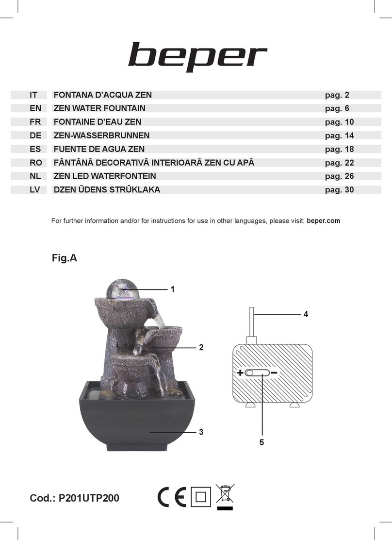
Beper
Beper P201UTP200 Use instruction

Campania International
Campania International Mari FT-405 Assembly instructions

Sunnydaze Decor
Sunnydaze Decor WNC-375 manual

for Living
for Living 19391 Assembly instructions
Murdock
Murdock A131-VR-BF4 Series Installation & maintenance instructions
Murdock
Murdock A132-BF4 Series Installation & maintenance instructions
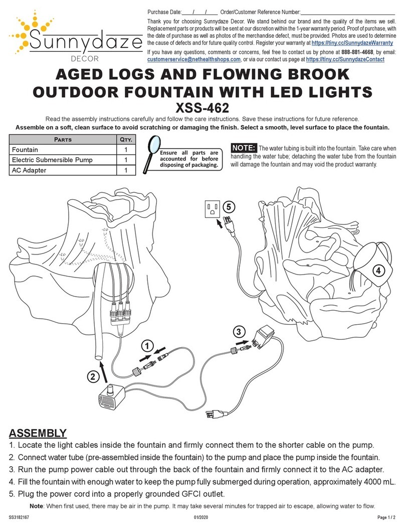
Sunnydaze Decor
Sunnydaze Decor XSS-462 manual

Garden Oasis
Garden Oasis LIGHTHOUSE FOUNTAIN owner's manual

Travis Industries
Travis Industries Ring of Fire owner's manual


