Bosch GMR 1 Professional User manual

* Des idées en action.
!!
!!""
""##
##$$
$$!!
!!""
""%%
%%&&
&&''
''((
((""
""&&
&&))))**
**##
##
ÁU~²Ýœ ÈULM¼«—
Operating Instructions
WW
WW ""
""##
##
o¡
ÙÙ
ÙÙ
à²Þà²Þ
à²Þà²Þ
Àπ—ß◊Õ§ŸË¡◊Õ°“√„™Èß“π
Petunjuk-Petunjuk
untuk Penggunaan
HıÎng dÕn s¯ dÙng
Instructions d’emploi
GMR 1
PROFESSIONAL
2 609 140 244 - Buch Seite 1 Dienstag, 22. Juni 2004 3:51 15

2 • 2 609 140 244 • 04.06
2 609 160 086
2 609 160 087
2 609 160 088
2 609 160 083
2 609 160 084
2 609 160 085
2 609 160 091
2 609 140 244 - Buch Seite 2 Dienstag, 22. Juni 2004 3:51 15

3 • 2 609 140 244 • 04.06
GMR 1
PROFESSIONAL
11
12
9
8
7
6
5 3
2
1
4
1
3
2
A
2
11
10
10
2 609 140 244 - Buch Seite 3 Dienstag, 22. Juni 2004 3:51 15

4 • 2 609 140 244 • 04.06
1
2
B
2
1
10
2
1
C
9
5
D
9
5
4 13
E
5
14
F
6
7
1
2
G
2
1
10
2 609 140 244 - Buch Seite 4 Dienstag, 22. Juni 2004 3:51 15

5 • 2 609 140 244 • 04.06
2
1
3
H
10
8
3
I
4
4
2
3
1
K
6
15
M
16
17
18
N
21
20
19
16
L
2 609 140 244 - Buch Seite 5 Dienstag, 22. Juni 2004 3:51 15

English - 1
While reading the operating instructions, unfold
the graphics page for the machine and leave it
open.
The numbering of the machine elements refers to
the representation of the machine on the graph-
ics page.
1
Motor unit
2
Routing base
3
Knurled screw for “depth-of-cut fine
adjustment”
4
Router bit*
5
Tightening nut with collet chuck
6
Guide plate
7
Base plate
8
Scale for coarse adjustment of depth-of-cut
9
Spindle locking button
10
Clamping lever
11
Base cover sleeve
12
On/Off switch
13
Open-end spanner
14
Collet chuck
15
Guide bushing*
16
Wing bolt for attachment of side stop
17
Parallel guide*
18
Wing bolt for parallel guide
19
Curve buffer*
20
Wing bolt for horizontal alignment of the side
stop
21
Wing bolt for locking of the horizontal align-
ment
*
Not all the illustrated or described accessories are
included as standard delivery.
Read all instructions.
Failure to
follow all instructions listed below
may result in electric shock, fire
and/or serious injury.
SAVE THESE INSTRUCTIONS.
■
Secure the workpiece.
Clamping devices or a
vise will hold the workpiece in place better than
the hand.
■
Always wait until the machine has come to
a complete stop before placing it down.
The
tool insert can jam and lead to loss of control
over the power tool.
■
Do not use a machine with a damaged
mains cable. Do not touch the damaged ca-
ble and pull the mains plug when the cable
is damaged while working.
Damaged cables
increase the risk of an electric shock.
■
Connect machines that are used in the
open via a residual current device (RCD).
■
Guide the machine against the workpiece
only when it is switched on.
Otherwise there
may be danger of kickback when the tool insert
jams in the workpiece.
■
Never cut over metal objects, nails and
screws.
The tool insert could become dam-
aged. Danger of injury.
■
Check the tight seating of the routing bit
before starting operation.
■
The allowable speed of the tool insert must
be at least as high as the maximum speed
stated on the machine.
Accessories driven in
excess of their allowable speed can be de-
stroyed.
■
The shank diameter of the tool insert must
correspond with the diameter of the tool
holder (collet).
Tool inserts that do not fit pre-
cisely in the tool holder of the machine rotate
irregularly, vibrate heavily and can lead to loss
of control.
■
Use only sharp, flawless tool inserts.
Dam-
aged or unsharp tool inserts can break or
cause kickback.
Tool Specifications
Laminate trimmer GMR 1
PROFESSIONAL
Article number 0 601 60A 0..
Rated input power [W] 550
Output power [W] 340
Idling speed [rpm] 33 000
Tool holder 6 mm/
1/4"
Weight according
EPTA-Procedure
01/2003 [kg] 1.5
Safety class
/ II
Please observe the article number on the type plate of your
machine. The trade names of the individual machines may
vary.
The values given are valid for nominal voltages [U] of 230/
240 V. However, these values can vary for lower voltages
and models made for specific countries.
Operating Controls
For Your Safety
2 609 140 244 - Buch Seite 1 Dienstag, 22. Juni 2004 3:51 15
6 • 2 609 140 244 • TMS • 17.06.04

English - 2
■Never touch the rotating tool insert. Danger
of injury.
■Use appropriate detectors to determine if
utility lines are hidden in the work area or
call the local utility company for assis-
tance.
Contact with electric lines can lead to fire and
electric shock. Damaging a gas line can lead
to explosion. Penetrating a water line causes
property damage or may cause an electric
shock.
■Hold the power tool only by the insulated
handles, when performing an operation
where the tool insert can run into hidden
wiring or its own mains cable. Contact with
a “live” wire can make metal parts of the power
tool “live” and lead to an electric shock.
The machine is intended for trimming edges in
wood, plastic and light building materials. It is
also suitable for routing of grooves, profiles and
slots as well as for contour routing.
■Before any work on the machine itself, pull the
power plug.
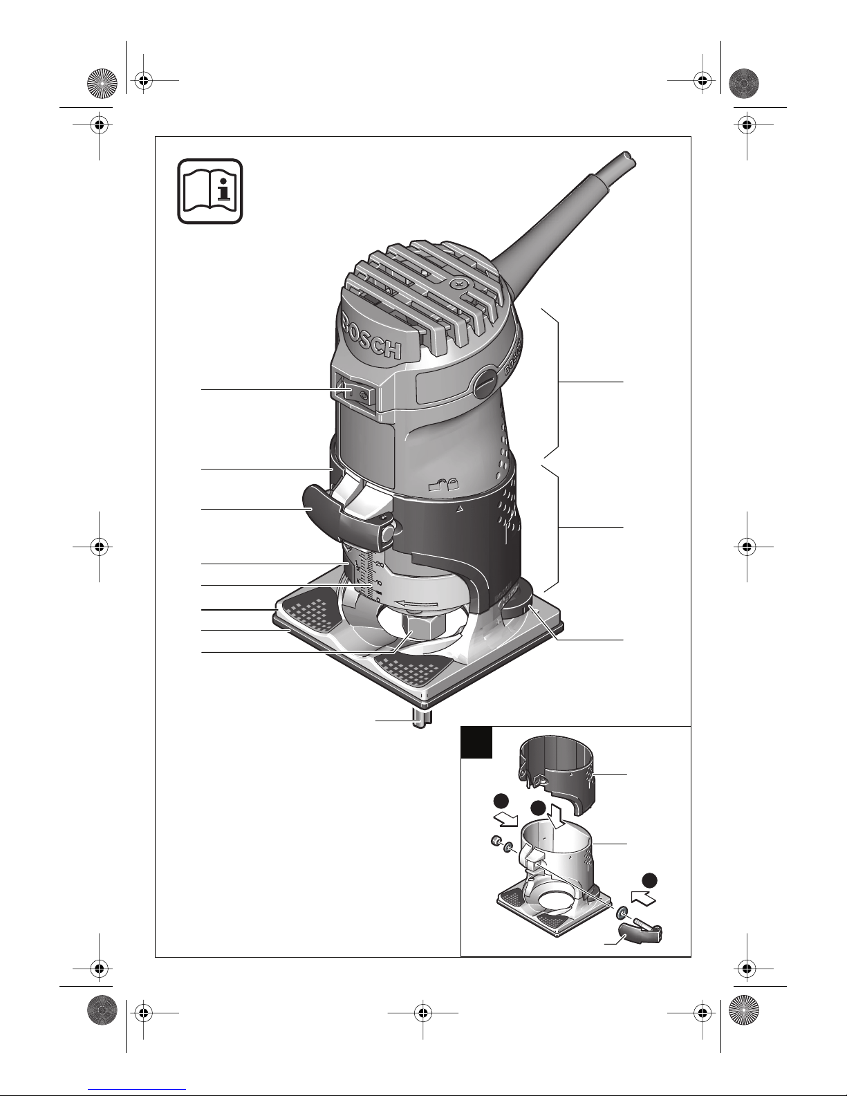
Assembling the Base Cover Sleeve
(see figure )
For assembly of the base cover sleeve 11, re-
move the clamping lever 10. Place the base
cover sleeve 11 onto the routing base 2 from
above and reassemble the clamping lever 10
again in such a manner that the motor unit 1 is
held securely in the routing base 2 when the
clamping lever is locked.
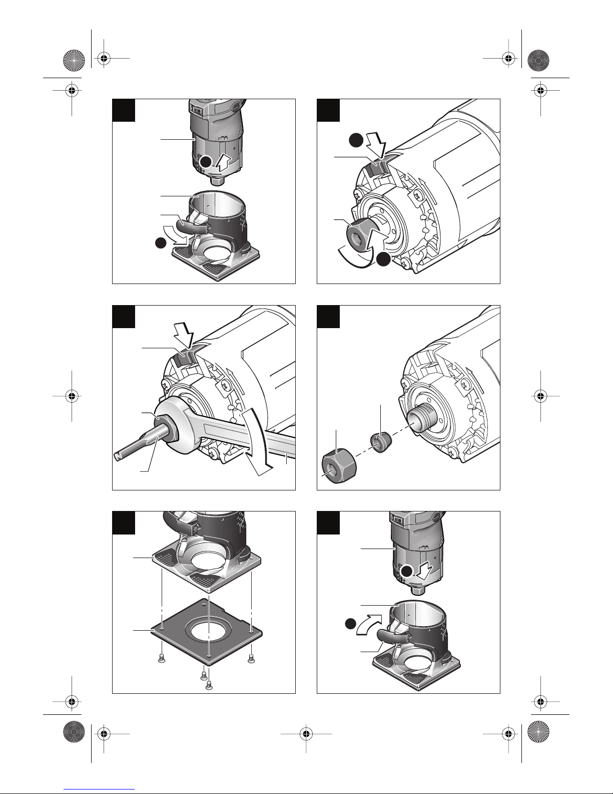
Disassembling the Motor Unit
(see figure )
For disassembly of the motor unit 1, open the
clamping lever 10 and turn the routing base 2 to
the symbol “ ” on the motor unit. Then pull the
motor unit 1 upwards out of the routing base 2.
Router Bit Selection
Depending on the processing and application,
router bits are available in the most different de-
signs and qualities:
Router bits made of high speed steel (HSS)
are suitable for the machining of soft materials,
e. g., soft wood and plastics.
Carbide tipped router bits (HM) are especially
suitable for hard and abrasive materials, e. g.,
hard wood.
Original router bits from the extensive Bosch ac-
cessories program are available at your special-
ized hardware store.
Inserting Router Bits
(see figures + )
■Before any work on the machine itself, pull the
power plug.
■It is recommended to wear protective gloves
when inserting or replacing router bits.
Disassemble the motor unit as described in the
respective section.
Press the spindle locking button 9 and keep it de-
pressed. If need be, turn the spindle by hand until
the lock engages.
■Press the spindle lock button only when at a
standstill.
Loosen the tightening nut 5 with an open-end
spanner 13 (size 17 mm) by turning it several
times, but do not unscrew the tightening nut.
Insert the shank of the router bit 4 as far as it will
go into the collet.
Tighten the tightening nut 5 with the open-end
spanner 13 (size 17 mm) and release the spindle
locking button 9.
Do not tighten the tightening nut of the
collet without a router bit inserted.
Replacing the Collet (see figure )
Depending on the routing tool to be used, differ-
ent collets can be inserted, see “Tool Specifica-
tions”.
Press the spindle locking button 9 and keep it de-
pressed. If need be, turn the spindle by hand until
the lock engages.
Completely unscrew the tightening nut 5.
Release the spindle locking button 9.
Insert the collet 14 and tighten the tightening
nut 5 again.
Do not tighten the tightening nut of the
collet without a router bit inserted.
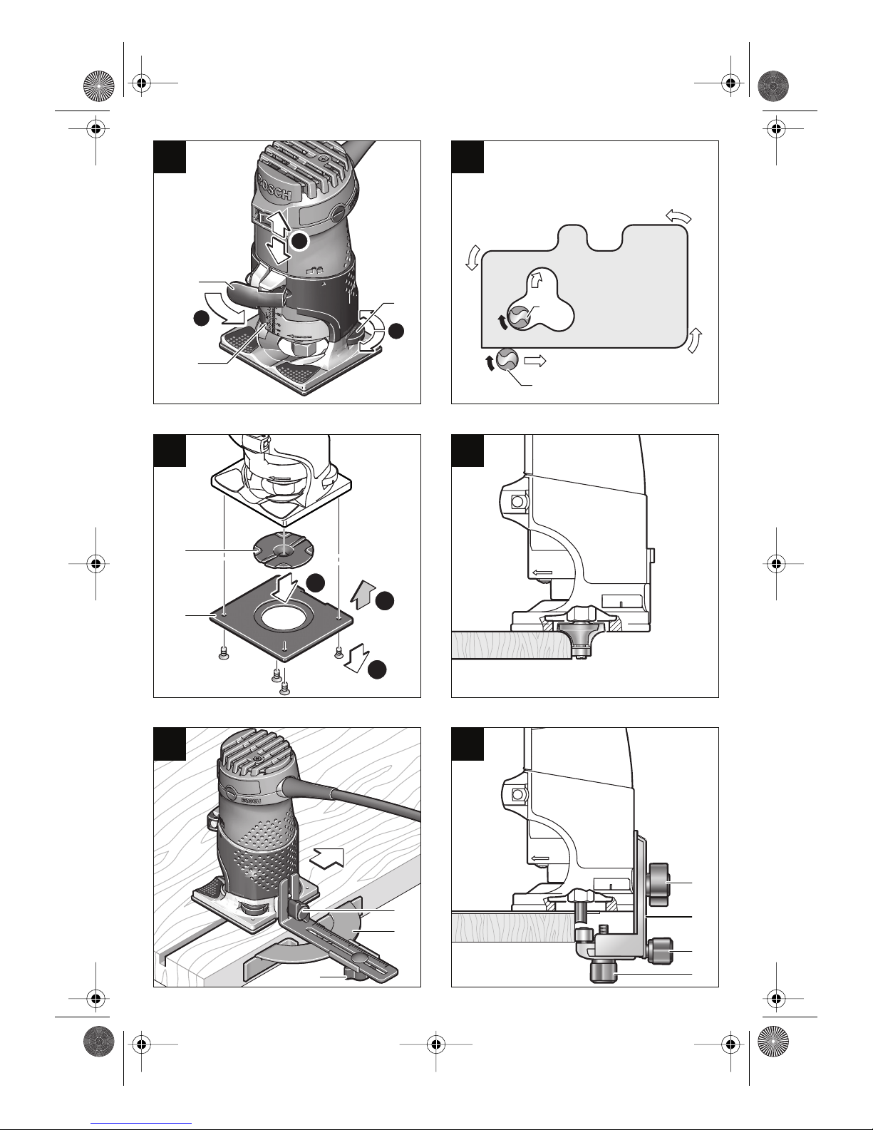
Mounting the Guide Plate
(see figure )
The guide plate 6 prevents the surface of delicate
materials from being scratched up.
Mount the guide plate 6 to the bottom side of the
base plate 7 with the 4 pan head screws.
Intended Use
Mounting
A
B
C D
E
F
2 609 140 244 - USA Seite 2 Dienstag, 22. Juni 2004 4:37 16
7 • 2 609 140 244 • TMS • 17.06.04

English - 3
Mounting the Motor Unit
(see figure )
With the clamping lever 10 opened, mount the
motor unit 1 by placing it into the routing base 2.
■Make sure that the “▲”mark on the routing
base 2 points toward the line under the
“ ” symbol on the motor unit 1. Otherwise
the machine can be damaged.
■After mounting, always check if the motor unit
sits tightly on the routing base. The pre-tension
of the clamping lever can be changed by read-
justing the nut
After mounting, has taken place, set the routing
base 2 to the “ ” symbol on the motor unit 1 and
lock the clamping lever 10.
Always use the correct voltage: The voltage of
the power source must agree with the values on
the nameplate of the machine.
Switching On and Off
To start the unit, move the On/Off switch 12 to I.
To switch off the unit, move the On/Off switch 12
to 0.
■Adjust the depth-of-cut only when the trimmer
is switched off.
Place the trimmer on the workpiece to be worked.
Open the clamping lever 10, turn the routing
base 2 to the “ ” symbol and slowly lower the
motor unit until the router bit touches the work-
piece. Fix the motor unit in this position by locking
the clamping lever 10.
Read the measuring value off the scale 8 and
note it down (zeroing). Add the desired
depth-of-cut to this value.
Open the clamping lever 10 and set the motor
unit to the calculated scale value. Turn the rout-
ing base 2 to the “ ” symbol and lock the clamp-
ing lever 10 again.
Check the adjusted depth-of-cut with a trial cut
and correct it, if necessary.
For fine adjustment of the depth-of-cut, set the
motor unit with the clamping lever 10 open to the
“ ” symbol. Adjust the desired depth-of-cut with
the knurled screw 3. Afterwards, lock the clamp-
ing lever to securely lock the motor unit in the
routing base.
Direction of Feed (see figure )
The feed motion of the trimmer must always be
carried out against the rotation direction of the
router bit (up-grinding).
When milling in the direction with the rotation of
the router bit (down-cutting), the router can break
loose, eliminating control by the user.
Routing Process
■Use the machine only with the routing base
mounted. Loss of control over the machine
can cause injuries.
■Before beginning the routing procedure, check
if the routing base 2 is positioned at the
“ ” symbol on the motor unit 1.
Adjust the depth-of-cut as described previously.
Place the machine onto the workpiece and switch
it on with the On/Off switch 12.
After finishing the cutting process, switch the ma-
chine off with the On/Off switch 12.
Routing with Guide Bushing
The guide bushing 15 enables template and pat-
tern routing on workpieces.
Inserting the Guide Bushing 15
(see figure )
Unscrew the 4 pan head screws on the bottom
side of the guide plate 6 and remove the guide
plate. Insert the guide bushing into the guide
plate and fasten it again to the base plate.
Routing Process
Select a router bit with a smaller diame-
ter than the inside diameter of the guide
bushing.
Place the machine with the guide bushing 15
against the template.
Guide the machine with the projecting guide
bushing along the template, applying slight lateral
pressure.
Note: The template must have a minimum thick-
ness of 8 mm, due to the projecting height of the
guide bushing.
Initial Operation
Setting the Depth-of-cut
(see figure )
G
H
Operating Instructions
I
K
2 609 140 244 - Buch Seite 3 Dienstag, 22. Juni 2004 3:51 15
8 • 2 609 140 244 • TMS • 17.06.04

English - 4
Shaping or Molding Applications
(see figure )
For shaping or molding applications without the
use of a parallel guide, the router must be
equipped with a pilot or a ball bearing.
Guide the machine from the side to the workpiece
until the pilot or the ball bearing of the trimmer
faces against the workpiece edge to be worked.
Guide the machine along the edge of the work-
piece, ensuring rectangular support. Excessive
pressure can damage the edge of the workpiece.
Routing with Parallel Guide
(see figure )
Fasten the parallel guide 17 to the routing base
with the wing bolt 16.
Adjust the desired depth setting on the parallel
guide 18 with the wing bolt.
Guide the machine with uniform feed and lateral
pressure against the parallel guide 17 along the
edge of the workpiece.
Routing with the Curve Buffer
(see figure )
The curve guide 19 is used for the routing of
rounded edges using routing bits without pilot or
ball bearing.
Fasten the curve guide 19 to the routing base
with wing bol 16.
Guide the machine with uniform feed along the
edge of the workpiece.
Lateral Clearance
In order to change the amount of material re-
moval, the lateral clearance between workpiece
and the guide roller of the curve guide can be ad-
justed.
Loosen wing bolt 21, set the desired lateral clear-
ance by readjusting wing bolt 20, then tighten
wing bolt 21 again.
Height
Adjust the vertical alignment of the curve guide
depending on the router bit in use and the thick-
ness of the material to be worked.
Loosen the wing bolt 16 on the curve guide, slide
the curve guide to the desired position and
tighten the wing bolt again.
■Before any work on the machine itself, pull the
power plug.
■For safe and proper working, always keep the
machine and its ventilation slots clean.
Should the machine fail in spite of careful manu-
facturing and testing, its repair should be carried
out by a Bosch power tools authorized service
agent.
In all correspondence and spare parts orders,
please always include the 10-digit article number
given on the nameplate of the machine.
Recycle raw materials instead of disposing
them as waste
The machine, its accessories and packaging ma-
terials should be sorted for environmentally-
friendly recycling.
These instructions are printed on chlorine-free re-
cycled paper.
The plastic components are labeled for catego-
rized recycling.
L
M
N
Maintenance and Cleaning
Environmental Protection
2 609 140 244 - Buch Seite 4 Dienstag, 22. Juni 2004 3:51 15
9 • 2 609 140 244 • TMS • 17.06.04
Other manuals for GMR 1 Professional
1
Table of contents
Other Bosch Laminate Trimmer manuals