16 | English
1 609 92A 11C | (12.11.14) Bosch Power Tools
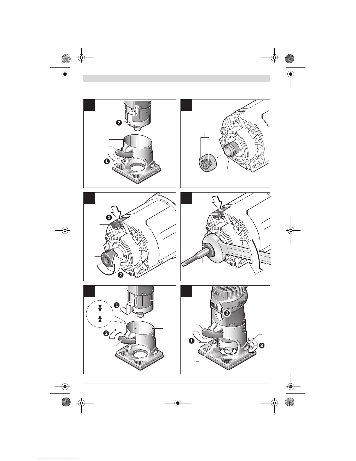
The collet 13 must have a slight amount of play when seated
in the tightening nut. The tightening nut 5must assemble eas-
ily. Should the tightening nut or collet be damaged, replace
immediately.
– Push the spindle lock button 9and keep it pressed. If re-
quired, rotate the motor spindle by hand until it locks.
– Unscrew the tightening nut 5with open-end spanner 15
turning in anticlockwise direction.
– Release the spindle lock button.
– If required, clean all parts tobe mounted prior to assem-
bling, using a soft brush or by blowing out with com-
pressed air.
– Start the new tightening nut on tool holder 14.
– Hand-tighten the tightening nut.
Donot tightenthe tightening nutof the collet withouta
router bit inserted. Otherwise the collet can be damaged.
Inserting a Router Bit (see figures C–D)
Depending on the application, router bits are available in the
most different designs and qualities.
Router bits made of high speed steel (HSS) are suitable for
the machining of soft materials, e. g. softwood and plastic.
Carbide tipped router bits (HM)are particularly suitable for
hard and abrasive materials, e. g. hardwood and aluminium.
Originalrouter bits fromthe extensive Bosch accessories pro-
gram are available at your specialist shop.
Only use clean router bits that are in perfect condition.
– Push the spindle lock button 9and keep it pressed. If re-
quired, rotate the motor spindle by hand until it locks.
– Loosen the tightening nut 5with the open-end spanner by
turning in anticlockwise direction 15.
– Insert the router bit into the collet. The shank of the router
bit must be immersed at least 20 mm into the collet.
– Retighten the tightening nut by turning in clockwise direc-
tion.
– Release the spindle lock button.
Donot tightenthe tightening nutof the collet withouta
router bit inserted. Otherwise the collet can be damaged.
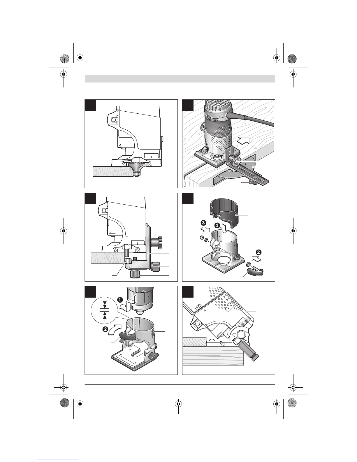
Mounting the Routing Base (see figure E)
Forrouting,the routingbase2must be mounted onthe motor
unit 1again.
– Release clamping lever 10, if tightened.
– Bring the two double arrows on the motor unit and the
routing base 2into alignment.
– Push the motor unit into the routing base and turn the mo-
tor unit in clockwise direction until the mark points
against the symbol.
– Push the motor unit further into the routing base.
– After mounting is completed, turn the mark on the rout-
ing base to the symbol on the motor unit.
– Lock the clamping lever.
After mounting, always check if the motor unit is seat-
ed tightly in the routing base.
If required, change the pre-tension of the clamping lever 10
(see “Readjusting the Clamping Lever”, page 17).
Dust/Chip Extraction
Dusts from materials such as lead-containing coatings,
some wood types, minerals and metal can be harmful to
one’s health. Touching or breathing-in the dusts can cause
allergic reactions and/or lead to respiratory infections of
the user or bystanders.
Certain dusts, such as oak or beech dust, are considered
as carcinogenic, especially in connection with wood-treat-
ment additives (chromate, wood preservative). Materials
containing asbestos may only be worked by specialists.
– As far aspossible, use a dust extraction system suitable
for the material.
– Provide for good ventilation of the working place.
– It is recommended to wear a P2 filter-class respirator.
Observe therelevant regulations in your country for the mate-
rials to be worked.
Operation
Adjusting the Depth-of-cut (see figure F)
Theadjustment ofthe depth-of-cutmayonly becarried
out when the router is switched off.
For coarse adjustment of the depth-of-cut, proceed as fol-
lows:
– Place the machine with the router bit mounted on the
workpiece to be machined.
– Release clamping lever 10, if tightened.
– Turn the routing base 2so that the mark points against
the symbol and slowly lower the motor unit until the
router bit touches the workpiece.
–Locktheclampinglever.
– Read the measuring value off the scale 8and note it down
(zeroing). Add the desired depth-of-cut to this value.
– Open the clamping lever and adjust the motor unit to the
calculated scale value.
– Turn the routing base so that the mark points against
the symbol and lock the clamping lever again.
– Checktheadjusteddepth-of-cutwithatrialcutand correct
it, if necessary.
For fine adjustment of the depth-of-cut, proceed as follows:
–Withtheclampinglever10 open, turnthe routing base so
that the mark points against the symbol.
– Adjust the desired depth-of-cut with thumbwheel 3.
–Locktheclampinglever.
Starting Operation
Observecorrect mains voltage! The voltageof the pow-
er source must agree with the voltage specified on the
nameplate of the machine. Power tools marked with
230 V can also be operated with 220 V.
Switching On and Off
To start the machine, set the On/Off switch 11 to I.
To switch off the machine, set the On/Off switch 11 to 0.
To save energy, only switch the power tool on when using it.
OBJ_BUCH-1137-002.book Page 16 Wednesday, November 12, 2014 8:16 AM