Section 1 Basic Information
1-2
Table of Contents
Section 1 Basic Information
Safe Servicing Practices........................................ 1-1
Table of Contents................................................. 1-2
Warnings and Safety Information.......................... 1-3
Precautions To Be Observed Before And During
Servicing To Avoid Possible Exposure To
Excessive Microwave Energy................................. 1-4
Before Servicing................................................... 1-4
Danger High Voltage ............................................ 1-4
Before Servicing................................................... 1-5
When Testing Is Completed.................................. 1-5
Microwave Measurement Procedure USA................ 1-6
Microwave Measurement Procedure Canada........... 1-7
Product Specification............................................ 1-8
Grounding Instructions......................................... 1-9
Electrical Requirements ........................................ 1-9
Oven Diagram...................................................... 1-10
Section 2 OperationSection 2 Operation
Operating Sequence Description............................ 2-1
Off Condition .................................................... 2-1
Cooking Condition............................................. 2-1
Ventilation Methods Hot Air Exhaust...................... 2-2
Power Level P-0 To P-90 Cooking.......................... 2-2
Oven Schematic-Off Condition............................... 2-3
Oven Schematic-Cooking Condition........................ 2-3
Touch Control Panel Assembly Outline................... 2-4
Component Descriptions....................................... 2-4
Door Open Mechanism ......................................... 2-4
Door Sensing And Primary Interlock Switch............ 2-4
Monitor Switch..................................................... 2-5
Thermal Cut-Out (Cavity)...................................... 2-5
Thermal Cut-Out (Hood)....................................... 2-5
Turntable Motor................................................... 2-5
Cooling Fan Motor................................................ 2-5
Hood Fan Motor................................................... 2-5
Hood Lamp.......................................................... 2-5
Section 3 Troubleshooting and Testing
Warnings and Cautions......................................... 3-1
Troubleshooting Guide Chart................................. 3-2
Test Procedures................................................... 3-3
Section 4 Component Teardown
Warnings and Cautions......................................... 4-1
Hood Exhaust Louver Removal.............................. 4-2
Removal Of Oven From Wall ................................. 4-2
Outer Case Removal............................................. 4-3
Power Transformer Removal................................. 4-3
High Voltage Rectifi er And High Voltage
Capacitor Removal ............................................... 4-4
Magnetron Removal ............................................. 4-4
Hood Fan Thermal Cut-Out Removal...................... 4-4
Hood Fan Motor Removal...................................... 4-5
Thermal Cut-Out (Cavity) Removal........................ 4-5
Cooling Fan Motor Removal .................................. 4-5
Turntable Motor And Food Lamp Sockets Removal.. 4-6
Oven Lamp And Lamp Socket Removal.................. 4-6
Servicing The Touch Control Panel ....................... 4-6
Control Panel Assembly, Control Unit And
Key Unit Removal................................................. 4-8
Door Sensing Switch, Primary Interlock
Switch And Monitor Switch Removal...................... 4-9
Door Sensing Switch, Primary Interlock
Switch, And Monitor Switch Adjustment................. 4-9
Door Replacement................................................ 4-10
Door Disassembly................................................. 4-11
.......... 4-12Humidity Sensor And Stirrer Motor Removal ..
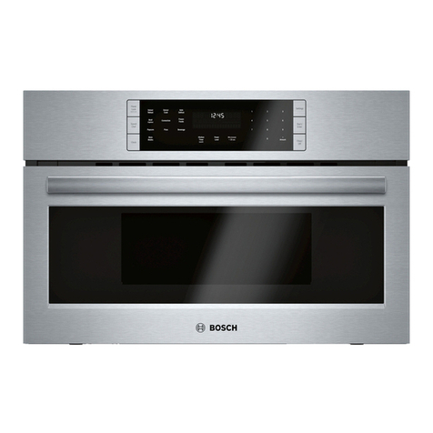
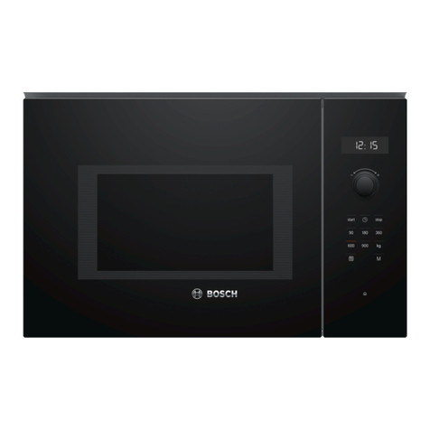
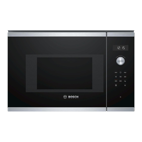
This Manual has been prepared to provide Authorized Service Personnel with Operation and Service Information for
Fault Codes .................................................... 2-1
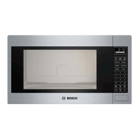
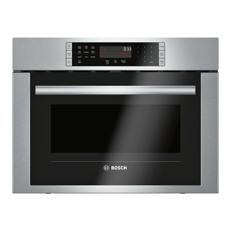
Bosch Microwave Hood Combination Models: HMV5053U, HMV5053C.
