Bosch WAT28400 Setup guide

Repair Instructions – Laundry
2017-05-22 / DIS 113_58300000186503_ara_en_c Copyright by BSH Hausgeräte GmbH Page 1 of 85
1 Concerning this document 3
1.1 Important information......................................................................................3
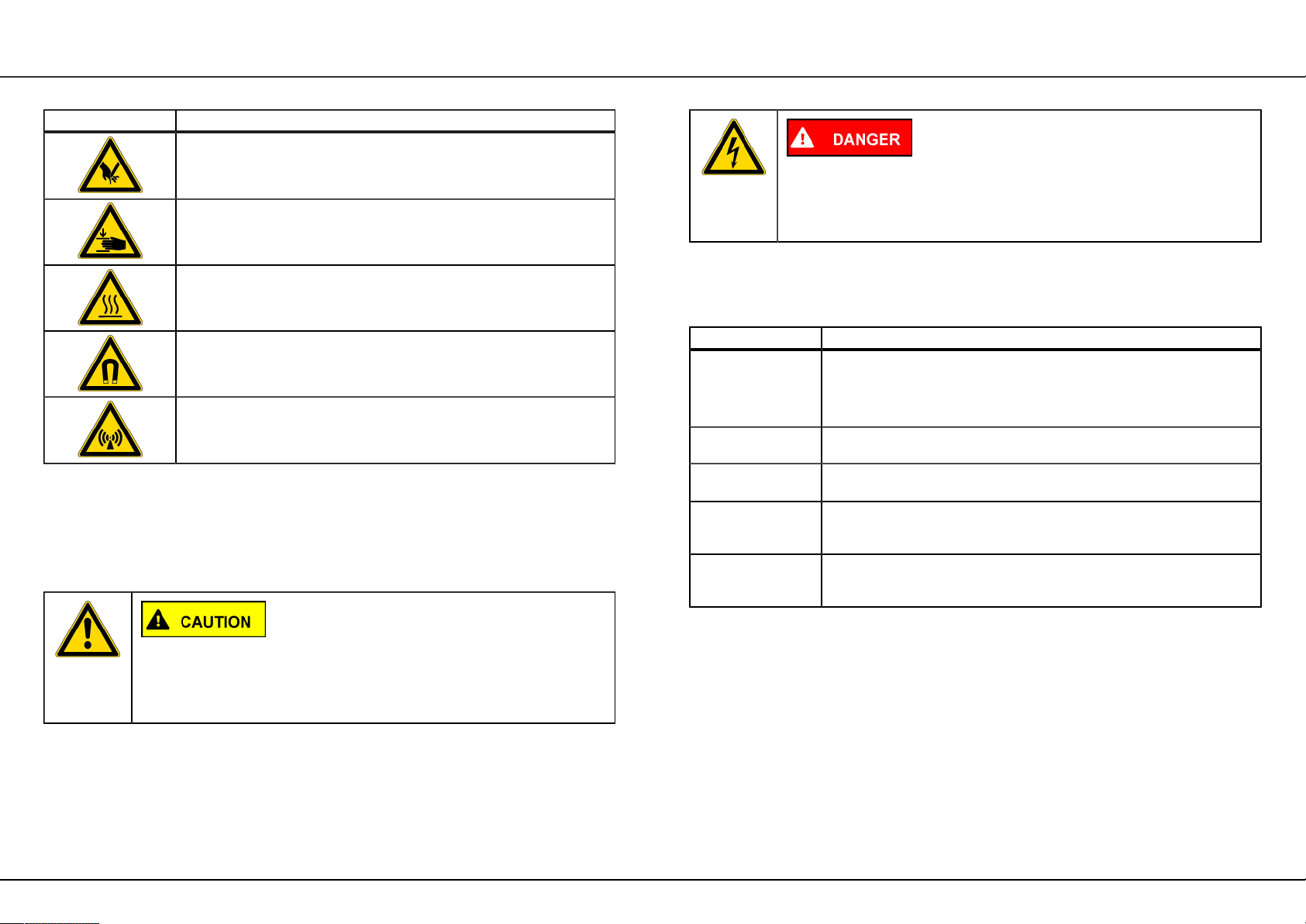
1.2 Explanation of symbols...................................................................................3
2 Safety 5
2.1 Qualification.................................................................................................... 5
2.2 General safety information............................................................................. 5
2.3 Product-specific safety information.................................................................6
2.4 Measures after each repair............................................................................ 7
3 Design and function 8
3.1 Safety system................................................................................................. 8
3.2 Safety switch...................................................................................................9
3.3 Flow-through sensor..................................................................................... 10
3.4 Turbidity sensor............................................................................................ 11
3.5 Light barrier...................................................................................................12
3.6 Calibrating the turbidity sensor.....................................................................13
3.7 Anti-crease function...................................................................................... 14
3.8 3D sensor..................................................................................................... 15
3.9 Load detection function with 3D sensor....................................................... 16
3.10 3G sensor....................................................................................................17
3.11 Unbalanced load detection........................................................................... 20
3.12 Heater with boil-dry protection......................................................................22
3.13 Siphon ..........................................................................................................23
3.14 Drip rail......................................................................................................... 24
3.15 Drain pump................................................................................................... 25
3.16 Aquastop....................................................................................................... 26
3.17 Door lock (electromagnetic)..........................................................................27
3.18 NTC...............................................................................................................29
4 Fault diagnosis 30
4.1 Malfunctions................................................................................................ 30
Gap between control panel and worktop too large...................................... 30
Drum lighting not functioning........................................................................31
Gasket leaking.............................................................................................. 32
Appliance won't switch on/off....................................................................... 32
Pump off....................................................................................................... 32
Does not use fabric softener with extra rinse...............................................33
Water runs in constantly............................................................................... 33
Water leakage...............................................................................................33
Takes too much water.................................................................................. 33
Takes fabric softener immediately................................................................ 33
Option buttons do not function..................................................................... 34
Display dark.................................................................................................. 34
Appliance is not functioning......................................................................... 34
Appliance does not heat up......................................................................... 34
4.2 Result faults................................................................................................ 36
Appliance is not spinning adequately...........................................................36
Creased laundry .......................................................................................... 37
Damaged washing / foreign objects............................................................. 37
Damaged washing / holes............................................................................ 38
Damaged washing / grease..........................................................................39
Damaged washing / colour fading................................................................ 39
Damaged washing / elastane content.......................................................... 39
Damaged washing (light stains)................................................................... 40
Damaged washing (matted)......................................................................... 40
Damaged washing (washing discoloured)....................................................41
Damaged washing (washing shrunk)........................................................... 41
Damaged washing (torn).............................................................................. 42
High detergent consumption.........................................................................42
Poor rinsing result........................................................................................ 43
4.3 Leaks............................................................................................................ 44
Door glass leaking........................................................................................ 44
Seal leaking.................................................................................................. 44
Seal deformed (leaking)............................................................................... 44
Leak between housing of detergent dispenser tray and magnetic
valves............................................................................................................ 45
Detergent dispenser leaking.........................................................................45
Foam coming out of detergent dispenser.................................................... 45
Drainage hose leaking..................................................................................45
Eliminate....................................................................................................... 46
4.4 Noises.......................................................................................................... 47
Noises........................................................................................................... 47
Noises when drum rotating.......................................................................... 47

Repair Instructions – Laundry
2017-05-22 / DIS 113_58300000186503_ara_en_c Copyright by BSH Hausgeräte GmbH Page 2 of 85
Noises during the spin cycle........................................................................ 47
Noises when water runs in...........................................................................47
4.5 Odours/biofilm.............................................................................................48
Chemical odour.............................................................................................48
Plastic odour................................................................................................. 48
Scorching odour............................................................................................48
Rotting/musty/stale odour............................................................................. 48
Detergent odour............................................................................................50
5 Test 51
5.1 Check NTC................................................................................................... 51
5.2 BLDC motor.................................................................................................. 52
6 Repairs 53
6.1 Siting the appliance...................................................................................... 53
6.2 Aligning the appliance.................................................................................. 54
6.3 Calibrating the load sensor.......................................................................... 55
6.4 Turbidity sensor calibration...........................................................................56
6.5 Starting/ending the demo programme..........................................................57
6.6 Correcting the gap........................................................................................ 58
6.7 Lengthening the inlet hose........................................................................... 60
6.8 Extending outlet hose [ 432060]...................................................................61
6.9 Flashing the operating module and power module...................................... 62
6.10 Replacing motor............................................................................................65
6.11 Removing/installing the 3G sensor...............................................................66
6.12 Replacing heater...........................................................................................68
6.13 Replacing NTC sensor................................................................................. 69
6.14 Replacing belt pulley.................................................................................... 70
6.15 Replacing the soap drawer.......................................................................... 71
6.16 Install repair set of soap drawer steam leakage ........................................ 73
6.17 Replacing the drain pump............................................................................ 76
6.18 Removing/installing front panel.................................................................... 77
6.19 Replacing injection valves............................................................................ 78
6.20 Removing/installing the power module.........................................................80
6.21 Incorrect and correct installation location of display module........................ 82
6.22 Removing/installing the inverter module...................................................... 83
6.23 Optionally Noises in inverter area ............................................................... 85

Concerning this document
2017-05-22 / DIS 113_58300000186503_ara_en_c Copyright by BSH Hausgeräte GmbH Page 3 of 85
1.1 Important information
Read and observe chapter 2 "Safety" before performing any work!
1.1.1 Purpose
These repair instructions form the basis for a systematic and safety conscious
procedure for the repair of domestic appliances.
These repair instructions include information about troubleshooting and repair.
1.1.2 Target group
These repair instructions are intended for persons who are familiar with equipment
technology and were instructed by BSH or an authorised body:
• Service technicians for the repair of domestic appliances
• Pre-assemblers in the spare part stockroom when determining required spare
parts
• Call centre employees during order acceptance
1.1.3 Other applicable documents
The following documents include additional relevant repair information:
• General repair instructions
• Error codes and service programs
• Circuit diagrams
• Exploded drawings
• Parts lists
• Repair videos
1.2 Explanation of symbols
1.2.1 Danger levels
The warning levels consist of a symbol and a signal word. The signal word
indicates the severity of the danger.
Warning level Meaning
Non-observance of the warning message will result in death or
serious injuries.
Non-observance of the warning message could result in death
or serious injuries.
Non-observance of the warning message could result in minor
injuries.
Non-observance of the warning message could result in dam-
age to property.
Table 1: Danger levels
1.2.2 Hazard symbols
Hazard symbols are symbolic representations which give an indication of the kind
of danger.
The following hazard symbols are used in this document:
Hazard symbol Meaning
General warning message
Danger from electrical voltage
Risk of explosion

Concerning this document
2017-05-22 / DIS 113_58300000186503_ara_en_c Copyright by BSH Hausgeräte GmbH Page 4 of 85
Hazard symbol Meaning
Danger of cuts
Danger of crushing
Danger from hot surfaces
Danger from strong magnetic field
Danger from non-ionizing radiation
Table 2: Hazard symbols
1.2.3 Structure of the warnings
Warnings in this document have a standardised appearance and a standardised
structure.
Type and source of danger!
Consequences of ignoring the warning.
► Actions to protect from danger.
The following example shows a warning that warns against electric shock due to
live parts. The measure for avoiding the danger is mentioned.
Risk of electric shock due to live parts!
► Disconnect the appliance from the mains at least 60 seconds
before starting the work .
1.2.4 General symbols
The following general symbols are used in this document:
Gen. symbol Meaning
Identification of a special tip (text and/or graphic)
Identification of a key or button
Identification of a material number
Identification of a condition (if ..., then ...)
Identification of a simple tip (only text)
Table 3: General symbols

Safety
2017-05-22 / DIS 113_58300000186503_ara_en_c Copyright by BSH Hausgeräte GmbH Page 5 of 85
2.1 Qualification
In Germany, only qualified electricians trained by BSH or an authorised body may
perform any repair work.
In other countries, only similarly trained qualified personnel is permitted to perform
the repair work.
Appliances must only be repaired by persons that are qualified, approved and
trained by BSH or an authorised body as instructed.
2.2 General safety information
2.2.1 All domestic appliances
Risk of electric shock due to live parts!
• Disconnect the appliance from the mains for at least 60 seconds before starting
work.
• Do not touch the housing, components and cables.
• For tests on an energised system, use a residual current circuit breaker.
• Discharge high-voltage capacitors.
Risk of injury from sharp edges!
• Wear protective gloves.
Risk of injury when dealing with harmful substances!
• Observe the associated safety data sheet!
Risk to the appliance's safety / function!
• Only use original spare parts.
Risk of damage to electrostatically sensitive components (ESDs)!
• Before touching ESDs, use an electrostatic protection system (wristband with
earth safe plug).
• Do not touch connections and conductor paths of the modules.
• Only transport ESDs in conductive materials or original packaging.
• Keep ESDs clear of electrostatically chargeable materials (i.e. plastic).

Safety
2017-05-22 / DIS 113_58300000186503_ara_en_c Copyright by BSH Hausgeräte GmbH Page 6 of 85
2.3 Product-specific safety information
2.3.1 Microwave ovens
Risk of scalding due to explosive escape of liquids in case of delayed
boiling!
• Before heating place a metal spoon in the liquid.
Health hazard due to non-ionising radiation!
• After any work on the appliance, check the tightness with leak rate
measurement.
2.3.2 Induction appliances
Induction appliances fulfil the relevant regulations for safety and electromagnetic
compatibility (EN 50366).
Danger to life due to magnetic fields!
• People with pacemakers should stay clear during repairs on an open
appliance!
Health hazard due to magnetic fields!
• People with medical devices (for example insulin pump / hearing aid) should
stay clear of the opened appliance!
2.3.3 Gas appliances
Explosion hazard due to escaping gas!
• Cut off the gas supply before working on gas carrying connections.
• Check tightness following work on connections carrying gas.
• Only repair gas appliances with original parts that were tested and released for
such use.
If you smell gas!
• Do not press any electrical switches.
• Extinguish / keep clear of open flames.
• Ensure that room is well ventilated.
• Close the gas isolating equipment.
2.3.4 Refrigerators and freezers
Risk of burns caused by refrigerants!
• Wear protective gloves and goggles.
Explosion hazard due to refrigerants!
• Do not solder pipe connections, only use Lokring connections.
• Do not press any electrical switches.
• Keep clear of thermal appliances.
• Extinguish / keep clear of open flames.
• Ensure that room is well ventilated.
2.3.5 Dryer with heat pump
Risk of burns caused by refrigerants!
• Wear protective gloves and goggles.
Explosion hazard due to refrigerants!
• Do not solder pipe connections, only use Lokring connections.
• Do not press any electrical switches.
• Keep clear of thermal appliances.
• Extinguish / keep clear of open flames.
• Ensure that room is well ventilated.

Safety
2017-05-22 / DIS 113_58300000186503_ara_en_c Copyright by BSH Hausgeräte GmbH Page 7 of 85
2.4 Measures after each repair
If the appliance is functional:
• Check according to VDE 0701 or country-specific regulations.
• Check external appearance, function and tightness.
• Document repair work, measured values and functional reliability.
If the appliance is not functional:
• Identify the appliance as “not functionally reliable”.
• Warn customers of commissioning and notify them in writing .

Design and function
2017-05-22 / DIS 113_58300000186503_ara_en_c Copyright by BSH Hausgeräte GmbH Page 8 of 85
3.1 Safety system
3.1.1 Structure
Fig. 1: Components of the safety system
1 Aquastop 4 Safety switch
2 electronics module 5 Base support
3 Float 6 Leakage water hose
The leakage water hose (6) of the Aquastop feeds into the base support (5). The
safety switch (4) and the float (3) are installed in the base support.
Aquastop (1) and safety switch (4) are electrically connected to the electronics
module (2).
3.1.2 Function
The safety system is active as soon as the appliance is switched on.
Water can leak from various points on the appliance:
• Leakage water hose of the Aquastop
• Outer tub
• Seal
The leaking water collects in the base support. The increasing water level in
the base support lifts the float and actuates the safety switch. The electronics
deactivate the Aquastop valve and stop the water supply. If there is water in the
outer tub, the electronics switch the pump on. The pump pumps the water out of
the tub and prevents large volumes of water from overflowing or leaking out. An
error message sounds and is indicated on the display.
As long as the safety switch is actuated, the appliance is not
ready for use.

Design and function
2017-05-22 / DIS 113_58300000186503_ara_en_c Copyright by BSH Hausgeräte GmbH Page 9 of 85
3.2 Safety switch
3.2.1 Structure
Fig. 2: Components of the safety switch
1 Float 2 Safety switch
The float (1) is in the base support. The safety switch (2) is situated above the float.
The float and switching contact of the safety switch are mechanically connected to
each other.
3.2.2 Function
If water infiltrates into the base support, the float rises and actuates the safety
switch.
The Aquastop valve is deactivated. The wash liquor is pumped off.

Design and function
2017-05-22 / DIS 113_58300000186503_ara_en_c Copyright by BSH Hausgeräte GmbH Page 10 of 85
3.3 Flow-through sensor
3.3.1 Structure
Fig. 3: Components of the flow-through sensor
1 Water inlet 3 Permanent magnet
2 Impeller 4 Reed contact switch
The impeller (2) with a permanent magnet (3) is located in the water inlet (1). The
circuit board with reed contact switch (4) is outside the water inlet in the area of
influence of the permanent magnet.
3.3.2 Function
Inflowing water moves the impeller and the permanent magnet. The rotating
magnetic field opens and closes the reed contact switch.
The appliance electronics determine the volume of water which has flowed in
based on the switching pulses of the reed contact switch.

Design and function
2017-05-22 / DIS 113_58300000186503_ara_en_c Copyright by BSH Hausgeräte GmbH Page 11 of 85
3.4 Turbidity sensor
3.4.1 Structure
Fig. 4: Components of the turbidity sensor
1 Seal 3 Circuit board with light barrier
2 Housing
The turbidity sensor consists of a circuit board (3) on which there is a light barrier.
The board is situated in a transparent housing (2) surrounded by a seal (1). The
housing protrudes into the outer tub.
3.4.2 Function
The turbidity sensor operates according to the principle of a light
barrier (Page 12). The water fills the space between the light-emitting diode and
phototransistor of the light barrier. The turbidity of the water determines the signal
strength on the phototransistor.
Fig. 5: Function of the turbidity sensor
1 Water 3 PCB
2 Light barrier
The turbidity sensor detects the turbidity of the water in the following programme
steps:
• Prewash
• Rinse
The measured turbidity provides information about the degree of soiling and sud
content in the water.
The measurement result influences the further operation of the wash programme:
• Changing the water for the main wash
• Addition of extra rinse cycles (max. 4 additional rinse cycles possible)
• Reduction of spin speed for reduced formation of suds
The turbidity sensor must be calibrated (Page 56) for the measurement.

Design and function
2017-05-22 / DIS 113_58300000186503_ara_en_c Copyright by BSH Hausgeräte GmbH Page 12 of 85
3.5 Light barrier
A light barrier is an electronic-optical system which detects the interruption of a
light beam.
3.5.1 Structure
Fig. 6: Components of the light barrier
1 Light-emitting diode 3 Phototransistor
2 Light beam
In the case of a light barrier the light-emitting diode (1) and the phototransistor (3)
are arranged opposite each other. The light beam (2) from the light-emitting diode
hits the phototransistor.
3.5.2 Function
The infrared light-emitting diode transmits light to the light-sensitive base of the
phototransistor. The phototransistor becomes conductive as a result. The voltage
on the phototransistor drops.
If the light beam is weakened or interrupted, e.g. by a turbid liquid, the light is no
longer adequate to activate the phototransistor.
The voltage on the phototransistor is evaluated by the electronics.

Design and function
2017-05-22 / DIS 113_58300000186503_ara_en_c Copyright by BSH Hausgeräte GmbH Page 13 of 85
3.6 Calibrating the turbidity sensor
The sensitivity and function of the turbidity sensor may be impaired by deposits.
The turbidity sensor is calibrated before each wash programme.
• Drum must be empty
• Door is not closed
• Switch on appliance, select programme but do not start.
the turbidity sensor is now calibrated.
Now the washing machine is ready for use.

Design and function
2017-05-22 / DIS 113_58300000186503_ara_en_c Copyright by BSH Hausgeräte GmbH Page 14 of 85
3.7 Anti-crease function
A lower speed during the spin interval and longer fluffing at the end of the
programme will reduce creasing.

Design and function
2017-05-22 / DIS 113_58300000186503_ara_en_c Copyright by BSH Hausgeräte GmbH Page 15 of 85
3.8 3D sensor
3.8.1 Structure
Fig. 7: Components of the 3D sensor
1 Holder 3 3D sensor
2 Permanent magnet
The 3D sensor consists of 3 Hall elements and a microcontroller. The Hall
elements are arranged in such a way that the 3 spatial axes are measured.
Fig. 8: Function of the 3D sensor
The permanent magnet is installed in the appliance near the 3D sensor.
3.8.2 Function
The 3D sensor uses the Hall effect.
If the drum drops due to the load or is deflected during the spin cycle, the position
of the permanent magnet moves with respect to the 3D sensor. This changes the
effect of the magnetic field on the Hall elements. The Hall elements generate Hall
voltages. The electronics evaluate the voltages.
In the case of appliances in which one 3D sensor and one 3G
sensor are fitted, the unbalanced load detection is monitored using
the 3G sensor.
The 3D sensor only monitors the load of the drum.

Design and function
2017-05-22 / DIS 113_58300000186503_ara_en_c Copyright by BSH Hausgeräte GmbH Page 16 of 85
3.9 Load detection function with 3D sensor
A washing machine load designates the amount of washing which fills the drum.
The load detection function determines the load. Depending on the load, the
control optimises the volume of water and the duration of the wash programme.
The load detection function with 3D sensor evaluates the mass of the washing.
Fig. 9: Principle of the load detection function with 3D sensor
The sensor measures how far the oscillation system drops when the drum is
loaded with washing.
The load is calculated based on the measurement result.
The 3D sensor is calibrated when the appliance is switched on. To
do this, the door must be closed and the appliance empty.

Design and function
2017-05-22 / DIS 113_58300000186503_ara_en_c Copyright by BSH Hausgeräte GmbH Page 17 of 85
3.10 3G sensor
The 3G sensor consists of 3 Hall elements and a microcontroller. The Hall
elements are arranged in such a way that the 3 spatial axes X, Y and Z are
measured.
3.10.1 Structure of the 3G sensor
Fig. 10: Components of the BLDC 3G sensor
Fig. 11: Components of the UMAC 3G sensor
1 Complete 3G sensor 3 PCB
2 Cover 4 Housing

Design and function
2017-05-22 / DIS 113_58300000186503_ara_en_c Copyright by BSH Hausgeräte GmbH Page 18 of 85
3.10.2 Measurement axes
Fig. 12: Measurement axis X
Fig. 13: Measurement axis Y

Design and function
2017-05-22 / DIS 113_58300000186503_ara_en_c Copyright by BSH Hausgeräte GmbH Page 19 of 85
Fig. 14: Measurement axis Z

Design and function
2017-05-22 / DIS 113_58300000186503_ara_en_c Copyright by BSH Hausgeräte GmbH Page 20 of 85
3.11 Unbalanced load detection
Unbalance occurs in rotating bodies whose mass is not distributed in a rotationally
symmetrical manner. The loaded drum of a washing machine always experiences
unbalance, as the laundry items are never optimally distributed around the axis of
rotation. If the unbalance cannot be offset by the oscillating system of the washing
machine, damage to the appliance and its installation location may occur.
The unbalanced load detection monitors unbalance in the drum during the spin
cycle start-up. If an unbalance occurs which is too high, the control unit reduces
the rotary speed of the drum. Damage caused by high unbalance is avoided in this
way. In order to measure the unbalance, the motor is accelerated to a constant
rotary speed for a specific time period. Appliances in newer model series measure
unbalance at various rotary speeds. The multilevel unbalance detection is more
accurate and ensures that the unbalance limit value provided is not exceeded for
the spin speed selected.
There are various procedures for measuring the unbalance:
• Determination of asynchronous motor operating values
• Determination of the drum deviation
Appliances with 3D/3G sensor determine the unbalance before acceleration to
the spin speed in 3 consecutive measurements.
Fig. 15: Unbalance measurement process schematic with 3D/3G sensor
A Measurement 1 D Duration of measurement 2
B Measurement 2 E Duration of measurement 3
C Measurement 3 F Decreased rotary speed after start-up attempt
Mea-
sure
Measurement
system
Measurement
rotary speed
Duration of
measurement
Measured
quantity
1 Motor tachome-
ter
100 rpm 20 seconds Rotary speed
fluctuation
2 3D/3G sensor 180 rpm 10 seconds Maximum ampli-
tude of the oscil-
lating system
3 3D/3G sensor 600 rpm 10 seconds Maximum ampli-
tude of the oscil-
lating system
Table 4: Measurements
If measurement 1 or 2 determines an impermissible unbalance, the control unit
reduces the rotary speed of the drum in order to improve the distribution of the
laundry. Then, measurement 1 is restarted.
A maximum total of 15 start-ups to the rotary speed are possible for measurements
1 and 2. For the wool wash programme, unbalance recognition is limited to 2 start-
up attempts.
Table of contents
Other Bosch Washer manuals

Bosch
Bosch WGG254FESN User manual

Bosch
Bosch WIS28440GB User manual

Bosch
Bosch XQG100-WGB254X00W User manual

Bosch
Bosch WAX32M41AU User manual

Bosch
Bosch WUU24T6XES User manual

Bosch
Bosch WUU28T48 User manual

Bosch
Bosch Programme Table User manual

Bosch
Bosch WGG244010 User manual

Bosch
Bosch WGG14400ES User manual

Bosch
Bosch WAK24160GR Specification sheet

Bosch
Bosch WIW24341EU User manual

Bosch
Bosch WAU28460IN Specification sheet

Bosch
Bosch WFMC4300UC/0 User manual

Bosch
Bosch LOGIXX 9 Product guide

Bosch
Bosch WAU28P89GB User manual

Bosch
Bosch WAX32M40SG User manual

Bosch
Bosch WAJ240L8SN User manual

Bosch
Bosch WM16W6H0EU Specification sheet

Bosch
Bosch WAW28760IR User manual

Bosch
Bosch WAP24201UC User manual