BOSSCO RT1 User manual

BOSS RT1
GUIDE
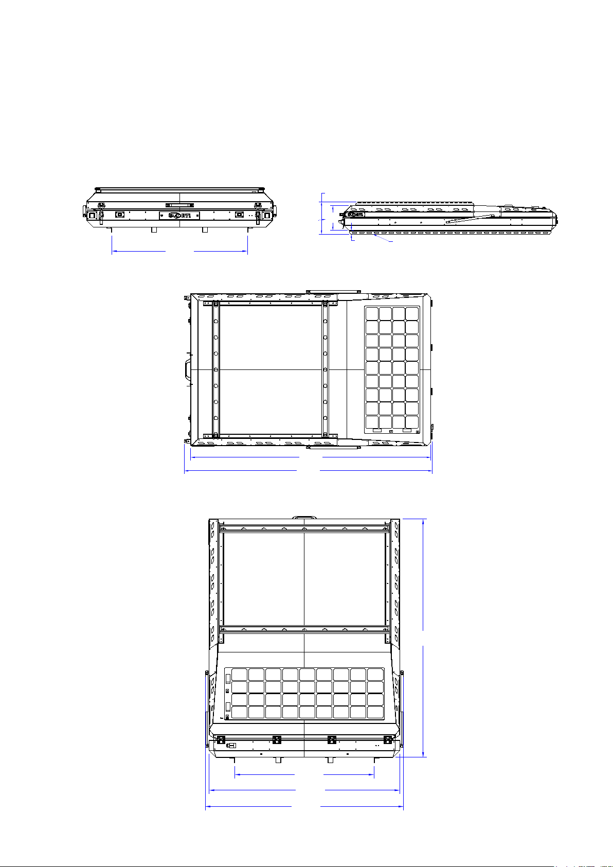
BOSS RT1 DIMENSIONS
Outside Closed:
Inside Open:
Weight:
2300L x 1450W x 260W (MM)
2165L x 1315W x 1800H
90 KG Approximately
0985-08-RTT
Title
12345678
12345678
A
B
C
D
E
F
A
B
C
D
E
F
0985-08-RTT
Size
0985-08-RTT
Project
Title
Checked
A3
Sheet 1 Rev.
Date
Dwg No.
THIRD ANGLE
PROJECTION D.W. 9/07/2020
11:05 AM
Drawn
Scale 1:10
A
D.W
BOSS ALUMINIUM
This drawing remains the property of
Boss Aluminium P/L and must not be
copied or reproduced in any way or form
without the written consent of Boss
Aluminium P/L
COPYRIGHT 2020
Factory 8/208 Canterbury road Bayswater north
Victoria3153 Ph:03-9729-3092 Fax:03-9729-3263
AD
AD
1060.0
1060.0
1453.4
1512.7
1816.3
AEAE
351.6
269.1
40
2306.4
2383.6
REAR VIEW
TOP VIEW
R/H SIDE VIEW
FRONT VIEW
INSIDE RAILS
SLOTED MOUNTING RAIL
OUTSIDE BODY
INSIDE MOUNTS
OVERALL INC GAS STRUTS
OPEN
CLOSED
0985-08-RTT
Title
12
3
4
5
6
7
8
1
23
4
5
67
8
A
B
C
D
E
F
A
B
C
D
E
F
0985-08-RTT
Size
0985-08-RTT
Project
Title
Checked
A3
Sheet 1
Rev.
Date
Dwg No.
THIRD ANGLE
PROJECTION D.W.
9/07/2020
11:05 AM
Drawn
Scale
1:10
A
D.W
BOSS
ALUMINIUM
This drawing remains the property of
Boss Aluminium P/L and must not be
copied or reproduced in any way or form
without the written consent of Boss
Aluminium P/L
COPYRIGHT 2020
Factory 8/208 Canterbury road Bayswater north
Victoria3153 Ph:03-9729-3092 Fax:03-9729-3263
AD
AD
1060.0
1060.0
1453.4
1512.7
1816.3
AEAE
351.6
269.1
40
2306.4
2383.6
REAR VIEW
TOP VIEW
R/H SIDE VIEW
FRONT VIEW
INSIDE RAILS
SLOTED MOUNTING RAIL
OUTSIDE BODY
INSIDE MOUNTS
OVERALL INC GAS STRUTS
OPEN
CLOSED
0985-08-RTT
Title
1
23
4
5
6
7
8
1
2
3
4
567
8
A
B
C
D
E
F
A
B
C
D
E
F
0985-08-RTT
Size
0985-08-RTT
Project
Title
Checked
A3
Sheet 1
Rev.
Date
Dwg No.
THIRD ANGLE
PROJECTION
D.W. 9/07/2020
11:05 AM
Drawn
Scale
1:10
A
D.W
BOSS
ALUMINIUM
This drawing remains the property of
Boss Aluminium P/L and must not be
copied or reproduced in any way or form
without the written consent of Boss
Aluminium P/L
COPYRIGHT 2020
Factory 8/208 Canterbury road Bayswater north
Victoria3153 Ph:03-9729-3092 Fax:03-9729-3263
AD
AD
1060.0
1060.0
1453.4
1512.7
1816.3
AEAE
351.6
269.1
40
2306.4
2383.6
REAR VIEW
TOP VIEW
R/H SIDE VIEW
FRONT VIEW
INSIDE RAILS
SLOTED MOUNTING RAIL
OUTSIDE BODY
INSIDE MOUNTS
OVERALL INC GAS STRUTS
OPEN
CLOSED
REAR VIEW
TOP VIEW
FRONT VIEW
R/H SIDE VIEW
0985-08-RTT
Title
12345678
12345678
A
B
C
D
E
F
A
B
C
D
E
F
0985-08-RTT
Size
0985-08-RTT
Project
Title
Checked
A3
Sheet 1 Rev.
Date
Dwg No.
THIRD ANGLE
PROJECTION D.W. 9/07/2020
11:05 AM
Drawn
Scale 1:10
A
D.W
BOSS ALUMINIUM
This drawing remains the property of
Boss Aluminium P/L and must not be
copied or reproduced in any way or form
without the written consent of Boss
Aluminium P/L
COPYRIGHT 2020
Factory 8/208 Canterbury road Bayswater north
Victoria3153 Ph:03-9729-3092 Fax:03-9729-3263
AD
AD
1060.0
1060.0
1453.4
1512.7
1816.3
AEAE
351.6
269.1
40
2306.4
2383.6
REAR VIEW
TOP VIEW
R/H SIDE VIEW
FRONT VIEW
INSIDE RAILS SLOTED MOUNTING RAIL
OUTSIDE BODY
INSIDE MOUNTS
OVERALL INC GAS STRUTS
OPEN
CLOSED

BOSS RT1 MOUNTING
• There are 2 slotted mounting rails that must be used to
mount the tent.
• Use 8 M8 bolts (4 on each side) to secure the tent to
your mounts.
• Ensure your mounts are adequite and hardware is tight.
0985-08-RTT
Title
12345678
12345678
A
B
C
D
E
F
A
B
C
D
E
F
0985-08-RTT
Size
0985-08-RTT
Project
Title
Checked
A3
Sheet 1 Rev.
Date
Dwg No.
THIRD ANGLE
PROJECTION D.W. 9/07/2020
11:05 AM
Drawn
Scale 1:10
A
D.W
BOSS ALUMINIUM
This drawing remains the property of
Boss Aluminium P/L and must not be
copied or reproduced in any way or form
without the written consent of Boss
Aluminium P/L
COPYRIGHT 2020
Factory 8/208 Canterbury road Bayswater north
Victoria3153 Ph:03-9729-3092 Fax:03-9729-3263
AD
AD
1060.0
1060.0
1453.4
1512.7
1816.3
AEAE
351.6
269.1
40
2306.4
2383.6
REAR VIEW
TOP VIEW
R/H SIDE VIEW
FRONT VIEW
INSIDE RAILS
SLOTED MOUNTING RAIL
OUTSIDE BODY
INSIDE MOUNTS
OVERALL INC GAS STRUTS
OPEN
CLOSED

CANVAS CARE
Before Use:
New canvas should be thoroughly wet before use and
allowed to dry.
• Boss Aluminium has wet the canvas once
• Repeat an additional 2-3 times to ensure sealing up of
the seams.
Maintaining Canvas Quality:
Clean only with cold water and brush - do not use soap
or detergent.
• Ensure product is completely dry prior to storage.
• Do not expose to petrol, oil or solvents.
• Restore well worn products with DYNAPROOF

CANVAS SPECIFICATIONS
WEIGHT:
• Dynaproofed: 275g/sq.m (8 oz) +/- 30gsm
CONSTRUCTION:
• Woven 65/35 Poly/Cotton Pla in Weave Japara
• 39.4 ends per cm. 26.8 picks per cm.
Yarn Count:
• 1/20 ECC x 1/20 ECC
Maximum Shrinkage
• 2% in Warp
Tear Resistance:
• WARP – 39N
• (AS 2001.2.10) WEFT – 28N
Breaking Force
• WARP – 1221N
• (AS 2001.2.3) WEFT – 1087N
Hydrostatic Head:
• 750mm min
• (AS 2001.2.17)
Cone Test:
• Pass

TELESCOPIC LADDER
Precautions
Safety Instructions
• Top of ladder and roof top tent locating pins are non-load bearing
• Do not stand on the top 3 steps/rungs
• Do not exceed 75°
• Ensure ladder is on an even, level and unmovable base
• Do not exceed maximum total load
• Always check that all buttons are on the “locked” position before you climb the ladder
• Always extend from the bottom rung
Before use:
• Ensure you are fit to use the ladder. Certain medical conditions, medications, alcohol or drug
use could make ladder use unsafe.
• When transporting ladders on roof racks or in trucks, ensure they are suitably placed and
secured to prevent damage.
• Inspect the ladder after delivery and before each use to confirm the condition and operation
of all parts.
• Visually check that the ladder is not damaged and is safe to use at the start of each working
day when the ladder is to be used.
• Ensure the ladder is suitable for the task at hand.
• Do not ever use a damaged ladder.
• Remove any contamination from the ladder, such as wet paint, mud, oil, ice or snow.
• Before use of the ladder in any work environment, a full risk assessment should be carried
out.
Positioning and erecting ladder
• Inclination angle should not exceed 75 degrees.
• Ladder should be on an even, level and unmovable base.
• The leaning ladder should be placed against a flat, non-fragile surface and should be
• secured before use, e.g. tied down or with an assistant standing on the bottom rung to secure
it.
• When positioning the ladder, take into account any risk of collision with the ladder from pe-
destrians, vehicles, doors or windows in the work area. Never set the ladder up in the
• vicinity of a closed fire exit as it may be opened urgently.
• Identify any electrical risks in the work area, such as overhead lines or other exposed electri-
cal equipment.
• The ladder should never be positioned on a slippery surface (such as ice, polished surfaces
or significantly contaminated solid surfaces) unless additional effective measures are
taken to prevent the ladder slipping.

Use of the ladder
• Do not exceed the maximum total load.
• Do not overreach. Users should keep the trunk of their body inside the stiles, with both feet on
the same step/rung throughout the task.
• Do not step off a leaning ladder at a higher level without additional security, such as tying off, or
the use of a suitable stability device.
• Do not use standing ladders to access another level.
• Do not stand on the top three steps/rungs of a leaning ladder.
• Ladders should only be used for light work of short durations.
• Do not use the ladder outside in adverse weather conditions, such as in a strong wind.
• Take precautions against children playing on the ladder.
• Face the ladder when ascending or descending.
• Keep a secure grip on the ladder when ascending or descending.
• Do not use the ladder as a bridge.
• Wear suitable footwear when climbing a ladder.
• Avoid excessive side loadings (e.g drilling brick or concrete)
• Do not spend long periods on a ladder without regular breaks.
• If you must use a ladder to gain access to a higher level, the top of the ladder should extend to
at least 1m above the landing point.
• Equipment to be carried while using a ladder should be light and easy to handle. If you are
lifting/lowering heavy or bulky equipment, the use of stairs, an elevator or a hauling bag with a
pulley system should be used.

Opening the Ladder
With automatic locking, each rung of the ladder has 2 locking pins that are blocked, which
are automatically inserted into the slots of the uprights when the ladder is extended.
The condition of the lock is indicated by the two black buttons on the side of each rung, as
shown below:
Complete Extension of the Ladder
1. Place the ladder onto firm and level ground, then place one foot on the lowest rung.
2. Lift the top rung up and ensure that the buttons are locked (as shown above) Repeat
this process with each of the lower rungs in turn, until the arms are completely extended.
Partial extension of the ladder
1. Place the ladder onto firm and level ground, then place one foot on the lowest rung.
2. Lift the top rung up and ensure that the buttons are locked (as shown above). Repeat
this process with each of the lower rungs until the desired ladder and rung height has
been achieved.
Shortening the Ladder
• Place the ladder on firm and level ground.
• Unlock the two buttons on the highest rung you can safely reach to lower the rung
down to the closed position. Continue doing this until the top rungs are all closed.
• Work your way down via each lower level, unlocking the buttons and then lowering
therungs until the ladder is all packed away.
Table of contents


