Bostitch 400 series User manual

400 & 500 SERIES
PNEUMATIC STAPLER
ENGRAPADORA NEUMÁTICA
AGRAFEUSE PNEUMATIQUE
104000REVD 5/99
OPERATION and MAINTENANCE MANUAL
MANUAL DE OPERACIÓN YDE MANTENIMIENTO
MANUEL D’INSTRUCTIONS ET D’ENTRETIEN
BOSTITCH®
Stanley Fastening Systems
BEFORE OPERATING THIS TOOL, ALL OPERATORS SHOULD STUDY THIS MANUAL TO
UNDERSTAND AND FOLLOW THE SAFETY WARNINGS AND INSTRUCTIONS. KEEP THESE
INSTRUCTIONS WITH THE TOOL FOR FUTURE REFERENCE. IF YOU HAVE ANY QUESTIONS,
CONTACT YOUR STANLEY-BOSTITCH REPRESENTATIVE OR DISTRIBUTOR.
ANTES DE OPERAR ESTAHERRAMIENTA, TODOS LOS OPERADORES DEBERÁN ESTUDIAR
ESTE MANUAL PARA PODER COMPRENDER YSEGUIR LAS ADVERTENCIAS SOBRE SEGURI-
DAD YLAS INSTRUCCIONES. MANTENGA ESTAS INSTRUCCIONES CON LA HERRAMIENTA
PARA FUTURA REFERENCIA, SI TIENE ALGUNA DUDA, COMUNÍQUESE CON SU REPRESEN-
TANTE DE STANLEY-BOSTITCH O CON SU DISTRIBUIDOR.
LIRE ATTENTIVEMENT LE PRÉSENT MANUEL AVANT D’UTILISER L’APPAREIL. PRÉTER UNE
ATTENTION TOUTE PARTICULIÈRE AUX CONSIGNES DE SÉCURITÉ ET AUX AVERTISSE-
MENTS. GARDER CE MANUEL AVEC L’OUTIL POUR FUTUR RÉFÉRENCE. SI VOUS AVEZ DES
QUESTIONS, CONTACTEZ VOTRE REPRÉSENTANT OU VOTRE CONCESSIONNAIRE
STANLEY-BOSTITCH.

INTRODUCTION
The Stanley-Bostitch 400 & 500 series staplers are precision-built tools, designed for high speed,
high volume stapling. These tools will deliver efficient, dependable service when used correctly
and with care. As with any fine power tool, for best performance the manufacturer’s instructions
must be followed. Please study this manual before operating the tool and understand the safety
warnings and cautions. The instructions on installation, operation and maintenance should be
read carefully, and the manuals kept for reference. NOTE: Additional safety measures may be
required because of your particular application of the tool. Contact your Stanley-Bostitch
representative or distributor with any questions concerning the tool and its use.
Stanley-Bostitch, Inc., East Greenwich, Rhode Island 02818.
INDEX
Safety Instructions . . . . . . . . . . . . . . . . . . . . . . . . . . . . . . . . . . . . . . . . . . . 3
Tool Specifications . . . . . . . . . . . . . . . . . . . . . . . . . . . . . . . . . . . . . . . . . . . 4
Air Supply: Fittings, Hoses, Filters, Air Consumption, Regulators,
Operating Pressure, Setting Correct Pressure . . . . . . . . . . . . . . . . . . 4 & 5
Lubrication . . . . . . . . . . . . . . . . . . . . . . . . . . . . . . . . . . . . . . . . . . . . . . . . . 5
Loading the Tool . . . . . . . . . . . . . . . . . . . . . . . . . . . . . . . . . . . . . . . . . . . . . 6
Dial-A-Depth™ Fastener Control Adjustment . . . . . . . . . . . . . . . . . . . . . . . . 6
Tool Operation . . . . . . . . . . . . . . . . . . . . . . . . . . . . . . . . . . . . . . . . . 7, 8 & 9
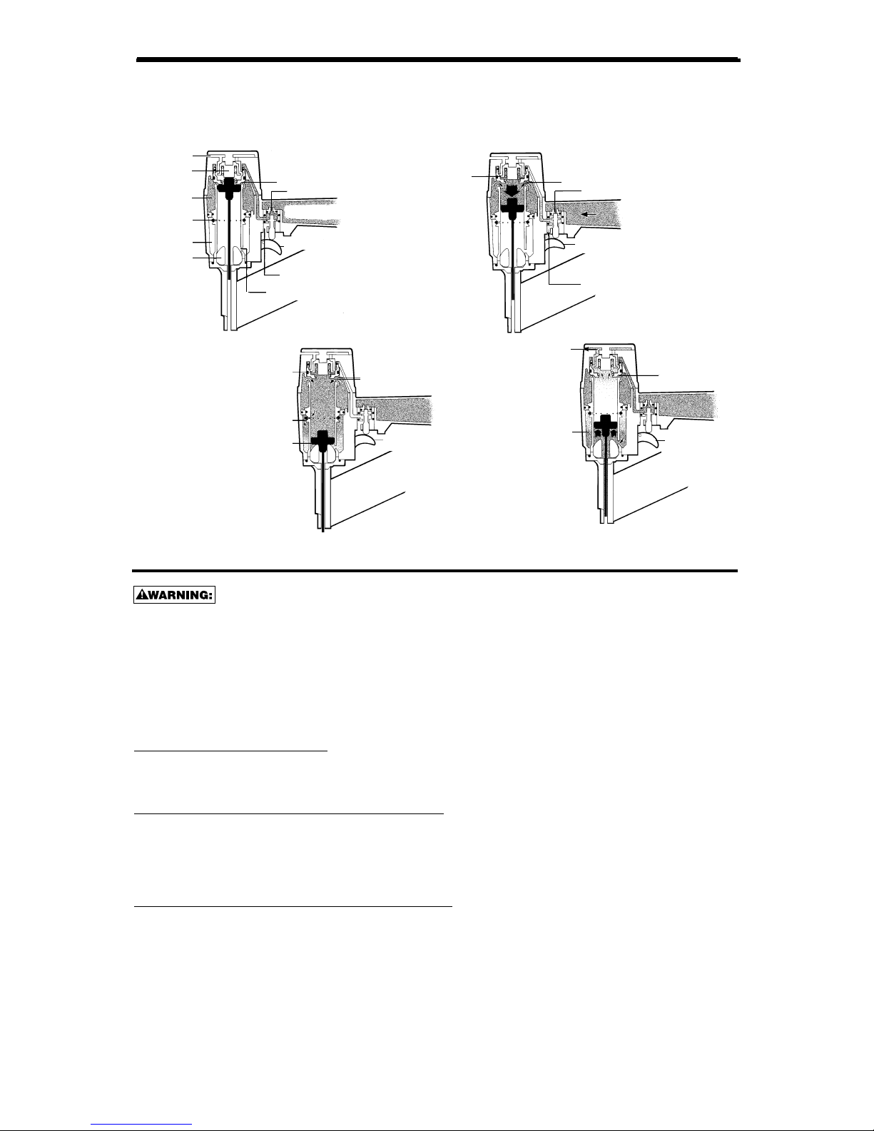
Basic Tool Operation (diagram) . . . . . . . . . . . . . . . . . . . . . . . . . . . . . . . . . . 9
Maintaining the Pneumatic Tool . . . . . . . . . . . . . . . . . . . . . . . . . . . . . . . . . 9
Trouble Shooting . . . . . . . . . . . . . . . . . . . . . . . . . . . . . . . . . . . . . . . . . . . 10
Directional Exhaust . . . . . . . . . . . . . . . . . . . . . . . . . . . . . . . . . . . . . . . . . . 11
Quick Release Magazine. . . . . . . . . . . . . . . . . . . . . . . . . . . . . . . . . . . . . . 11
Accessories . . . . . . . . . . . . . . . . . . . . . . . . . . . . . . . . . . . . . . . . . . . . . . . 11
NOTE:
Stanley-Bostitch tools have been engineered to provide excellent customer satisfaction and are
designed to achieve maximum performance when used with precision Stanley-Bostitch fasteners
engineered to the same exacting standards.
Stanley-Bostitch cannot assume responsibility for product performance if our tools are
used with fasteners or accessories not meeting the specific requirements established for
genuine Stanley-Bostitch nails, staples and accessories.
LIMITED WARRANTY
Stanley-Bostitch, Inc., warrants to the original retail purchaser that this product is free from
defects in material and workmanship, and agrees to repair or replace, at Stanley-Bostitch's
option, any defective product within 1 year from the date of purchase. This warranty is not
transferable. It only covers damage resulting from defects in material or workmanship, and
it does not cover conditions or malfunctions resulting from normal wear, neglect, abuse, accident
or repairs attempted or made by other than our regional repair center or authorized warranty
service center. Driver blades, bumpers and o-rings are considered normally wearing parts.
THIS WARRANTY IS IN LIEU OF ALL OTHER EXPRESS WARRANTIES. ANY WARRANTY OF
MERCHANTABILITY OR FITNESS FOR A PARTICULAR PURPOSE IS LIMITED TO THE
DURATION OF THIS WARRANTY. STANLEY-BOSTITCH SHALL NOT BE LIABLE FOR ANY
INCIDENTAL OR CONSEQUENTIAL DAMAGES.
This warranty is limited to sales in the United States and Canada. Some states do not allow
limitations on how long an implied warranty lasts, or the exclusion or limitation of incidental or
consequential damages, so the above limitations or exclusions may not apply to you. This
warranty gives you specific legal rights, and you may also have other rights which vary from state
to state.
To obtain warranty service, return the product at your expense together with proof of purchase to
a Stanley-Bostitch Regional or authorized warranty repair center. You may call us at
1-800-556-6696 for the location of authorized warranty service centers in your area.
FASTENERS
PROTECT YOUR TOOLS
USE ONLY GENUINE
-2-

-3-
SAFETY INSTRUCTIONS
EYE PROTECTION which conforms to ANSI specifications and provides protection
against flying particles both from the FRONT and SIDE should ALWAYS be worn
by the operator and others in the work area when loading, operating or servicing
this tool. Eye protection is required to guard against flying fasteners and debris,
which could cause severe eye injury.
The employer and/or user must ensure that proper eye protection is worn. Eye
protection equipment must conform to the requirements of the American National
Standards Institute, ANSI Z87.1-1989 and provide both frontal and side protection.
NOTE: Non-side shielded spectacles and face shields alone do not provide ade-
quate protection.
CAUTION: ADDITIONAL SAFETY PROTECTION will be required in some environ-
ments. For example, the working area may include exposure to noise level which
can lead to hearing damage. The employer and user must ensure that any necessary
hearing protection is provided and used by the operator and others in the work area.
Some environments will require the use of head protection equipment. When
required, the employer and user must ensure that head protection conforming to
ANSI Z89.1 1986 is used.
AIR SUPPLY AND CONNECTIONS
Do not use oxygen, combustible gases, or bottled gases as a power source for this
tool as tool may explode, possibly causing injury.
Do not use supply sources which can potentially exceed 200 P.S.I.G. as tool may
burst, possibly causing injury.
The connector on the tool must not hold pressure when air supply is disconnect-
ed. If a wrong fitting is used, the tool can remain charged with air after discon-
necting and thus will be able to drive a fastener even after the air line is discon-
nected possibly causing injury.
Do not pull trigger or depress contact arm while connected to the air supply as the
tool may cycle, possibly causing injury.
Always disconnect air supply: 1.) Before making adjustments; 2.) When servicing
the tool; 3.) When clearing a jam; 4.) When tool is not in use; 5.) When moving to a
different work area, as accidental actuation may occur, possibly causing injury.
LOADING TOOL
When loading tool: 1.) Never place a hand or any part of body in fastener dis-
charge area of tool; 2.) Never point tool at anyone; 3.) Do not pull the trigger or
depress the trip as accidental actuation may occur, possibly causing injury.
OPERATION
Always handle the tool with care: 1.) Never engage in horseplay; 2.) Never pull
the trigger unless nose is directed toward the work; 3.) Keep others a safe dis-
tance from the tool while tool is in operation as accidental actuation may occur,
possibly causing injury.
The operator must not hold the trigger pulled on contact arm tools except dur-
ing fastening operation as serious injury could result if the trip accidentally con-
tacted someone or something, causing the tool to cycle.
Keep hands and body away from the discharge area of the tool. A contact arm tool
may bounce from the recoil of driving a fastener and an unwanted second fasten-
er may be driven possibly causing injury.
Check operation of the contact arm mechanism frequently. Do not use the tool if
the arm is not working correctly as accidental driving of a fastener may result. Do
not interfere with the proper operation of the contact arm mechanism.
Do not drive fasteners on top of other fasteners or with the tool at an overly steep
angle as this may cause deflection of fasteners which could cause injury.
Do not drive fasteners close to the edge of the work piece as the wood may split,
allowing the fastener to be deflected possibly causing injury.
MAINTAINING THE TOOL
When working on air tools note the warnings in this manual and use extra care
when evaluating problem tools.

-4-
400 & 500 SERIES TOOL SPECIFICATIONS
TOOL AIR FITTING:
This tool uses a free-flow connector plug, 1/4”N.P.T. The minimum inside diameter should be .200”(5mm).
The fitting must be capable of discharging tool air pressure when disconnected from the air supply.
OPERATING PRESSURE:
The operating pressure of the 400 & 500 tools is 70 to 120 p.s.i. (4.9 to 8.4 kg/cm2). Select the operating
pressure within this range for best fastener performance. DO NOT EXCEED THIS RECOMMENDED
OPERATING PRESSURE.
AIR CONSUMPTION:
Series 400 requires 2.1 cubic feet per minute (59.5 liters per minute) of free air to operate at the rate of
100 fasteners per minute, at 80 p.s.i. (5.6kg/cm2).
Series 500 requires 2.6 cubic feet per minute. (73.6 liters per minute) of free air to operate at a rate of
100 fasteners per minute, at 80 p.s.i. (5.6 kg/cm2).
For Series 400 and 500 tools, take the actual rate at which the tool will be run to determine the amount
of air required.
For instance, if your fastener usage averages 50 fasteners per minute, you need 50% of the c.f.m. listed
above which is required to operate the tool at 100 fasteners per minute.
OPERATION
MODEL LENGTH HEIGHT WIDTH WEIGHT
438S4 13.98" (355mm) 8.84" (225 mm) 2.50" (64 mm) 4.05 lb. 1.83 (kg)
438S5 13.98" (355mm) 8.84" (225 mm) 2.50" (64 mm) 3.95 lb. 1.79 (kg)
438S2 13.98" (355mm) 8.84" (225 mm) 2.50" (64 mm) 4.55 lb. 2.06 (kg)
438S2R 13.98" (355mm) 8.84" (225 mm) 2.50" (64 mm) 4.70 lb. 2.13 (kg)
450S2 13.98" (355mm) 8.84" (225 mm) 2.50" (64 mm) 4.60 lb. 2.08 (kg)
538S4 13.98" (355mm) 8.84" (225 mm) 2.86" (73 mm) 4.15 lb. 1.88 (kg)
538S5 13.98" (355mm) 8.84" (225 mm) 2.86" (73 mm) 4.05 lb. 1.83 (kg)
MODEL STAPLE SERIES CROWN WIDTH WIRE SIZE MAXIMUM LEG LENGTH
438S4 16S4 1/2" (12.7mm) .061"x.056" (1.55 mm x 1.42 mm) 1.5" (38 mm)
438S5 17S5 7/16" (11.1mm) .057"x.051" (1.45 mm x 1.30 mm) 1.5" (38 mm)
438S2 16S2 1" (25.4 mm) .062" (1.57 mm) 1.5" (38 mm)
438S2R 16S2 1" (25.4 mm) .062" (1.57 mm) 1.5" (38 mm)
450S2 16S2 1" (25.4 mm) .062" (1.57 mm) 2" (50 mm)
538S4 16S4 1/2" (12.7 mm) .061"x.056" (1.55 mm x 1.42mm) 1.5" (38 mm)
538S5 16S5 7/16" (11.1 mm) .057"x.051" (1.45 mm x 1.30 mm) 1.5" (38 mm)
STANLEY-BOSTITCH OFFERS THREE TYPES OF OPERATION FOR THIS SERIES TOOL.
CONTACT TRIP
The common operating procedure on “Contact Trip”tools is for the operator to contact the work to actuate
the trip mechanism while keeping the trigger pulled, thus driving a fastener each time the work is contacted.
This will allow rapid fastener placement on many jobs, such as sheathing, decking and pallet assembly.
All pneumatic tools are subject to recoil when driving fasteners. The tool may bounce, releasing the trip,
and if unintentionally allowed to recontact the work surface with the trigger still actuated (finger still holding
trigger pulled) an unwanted second fastener will be driven.
SEQUENTIAL TRIP
The Sequential Trip requires the operator to hold the tool against the work before pulling the trigger. This
makes accurate fastener placement easier, for instance on framing, toe nailing and crating applications. The
Sequential Trip allows exact fastener location without the possibility of driving a second fastener on recoil, as
described under “Contact Trip”. The Sequential Trip Tool has a positive safety advantage because it will not
accidentally drive a fastener if the tool is contacted against the work –or anything else –while the operator
is holding the trigger pulled.
TRIGGER OPERATED
The Trigger Operated model is cycled by actuation of the trigger only. This model does not have a
Contact Arm and is intended for use only where a Contact Arm CANNOT be used to satisfy the
requirements of the application. The Trigger Operated tool will cycle each time the trigger is actuated.
MODEL IDENTIFICATION:
Refer to Operation Instructions on page 7 before proceeding to use this tool.
CONTACT TRIP SEQUENTIAL TRIP TRIGGER OPERATED
Identified by: Identified by: Identified by:
BLACK TRIGGER GRAY TRIGGER BLACK TRIGGER
All screws and nuts are metric.
FASTENER SPECIFICATIONS:

AIR SUPPLY AND CONNECTIONS
Do not use oxygen, combustible gases, or bottled gases as a power
source for this tool as tool may explode, possibly causing injury.
FITTINGS:
Install a male plug on the tool which is free flowing and which will release air pressure from the
tool when disconnected from the supply source.
HOSES:
Air hoses should have a minimum of 150 p.s.i. (10.6 kg/cm2) working pressure rating or 150
percent of the maximum pressure that could be produced in the air system. The supply hose
should contain a fitting that will provide “quick disconnecting”from the male plug on the tool.
SUPPLYSOURCE:
Use only clean regulated compressed air as a power source for this tool. NEVER USE
OXYGEN, COMBUSTIBLE GASES, OR BOTTLED GASES, AS A POWER SOURCE FOR
THIS TOOL AS TOOL MAY EXPLODE.
REGULATOR:
A pressure regulator with an operating pressure of 0 - 125 p.s.i. (0 - 8.79 KG/CM2) is required
to control the operatiing pressure for safe operation of this tool. Do not connect this tool to air
pressure which can potentially exceed 200 p.s.i. (14 KG/CM2)as tool may fracture or burst,
possibly causing injury.
OPERATING PRESSURE:
Do not exceed recommended maximum operating pressure as tool wear will be greatly
increased. The air supply must be capable of maintaining the operating pressure at the tool.
Pressure drops in the air supply can reduce the tool’s driving power. Refer to “TOOL
SPECIFICATIONS”for setting the correct operating pressure for the tool.
FILTER:
Dirt and water in the air supply are major causes of wear in pneumatic tools. A filter will help
to get the best performance and minimum wear from the tool. The filter must have adequate
flow capacity for the specific installation. The filter has to be kept clean to be effective in pro-
viding clean compressed air to the tool. Consult the manufacturer’s instructions on proper
maintenance of your filter. A dirty and clogged filter will cause a pressure drop which will
reduce the tool’s performance.
LUBRICATION
Frequent, but not excessive, lubrication is required for best performance. Oil added through the air line
connection will lubricate the internal parts. Use STANLEY-BOSTITCH Air Tool Lubricant, Mobil Velocite
#10, or equivalent. Do not use detergent oil or additives as these lubricants will cause accelerated
wear to the seals and bumpers in the tool, resulting in poor tool performance and frequent tool
maintenance.
If no airline lubricator is used, add oil during use into the air fitting on the tool once or twice a day.
Only a few drops of oil at a time is necessary. Too much oil will only collect inside the tool and will be
noticeable in the exhaust cycle.
COLD WEATHER OPERATION:
For cold weather operation, near and below freezing, the moisture in the air line may freeze and pre-
vent tool operation. We recommend the use of STANLEY-BOSTITCH WINTER FORMULA air tool
lubricant or permanent antifreeze (ethylene glycol) as a cold weather lubricant.
CAUTION: Do not store tools in a cold weather environment to prevent frost or ice formation
on the tools operating valves and mechanisms that could cause tool failure.
NOTE: Some commercial air line drying liquids are harmful to “O”-rings and seals –do not use
these low temperature air dryers without checking compatibility.
-5-

-6-
EYE PROTECTION which conforms to ANSI specifications and provides protection
against flying particles both from the FRONT and SIDE should ALWAYS be worn
by the operator and others in the work area when loading, operating or servicing
this tool. Eye protection is required to guard against flying fasteners and debris,
which could cause severe eye injury.
The employer and/or user must ensure that proper eye protection is worn. Eye
protection equipment must conform to the requirements of the American National
Standards Institute, ANSI Z87.1-1989 and provide both frontal and side protection.
NOTE: Non-side shielded spectacles and face shields alone do not provide ade-
quate protection.
TO PREVENT ACCIDENTAL INJURIES:
•Never place a hand or any other part of the body in fastener discharge area of tool while
the air supply is connected.
•Never point the tool at anyone else.
•Never engage in horseplay.
•Never pull the trigger unless nose is directed at the work.
•Always handle the tool with care.
•Do not pull the trigger or depress the trip mechanism while loading the tool.
LOADING THE 400 & 500
A
B
1. Move pusher to rear until
latched. Cover will open.
Pusher front will drop into
notch on top of magazine
assembly.
2. Drop staple stick over magazine and
slide forward. Repeat until magazine
is loaded, allowing enough space for
pusher to disengage the magazine
and the cover to close.
Approximately 1/2" (13mm)
3. Pull and hold top part of
knob (A) and depress
bottom part of knob (B) in
a clockwise direction to
release pusher.
The DIAL-A-DEPTH™Fastener Control adjustment feature provides close control of the fastener drive
depth; from flush with the work surface to shallow or deep countersink. First, set the air pressure for
consistent drive in the specific work as described on page 5, then use the DIAL-A-DEPTH™Fastener
Control adjustment to give the desired depth of drive.
TO ADJUST DIAL-A DEPTH™FASTENER CONTROL ADJUSTMENT:
“DIAL-A-DEPTH™” FASTENER CONTROL ADJUSTMENT
Always disconnect air supply: 1. Before making adjustments; 2. When servicing the tool; 3. When
clearing a jam; 4. When tool is not in use; 5. When moving to a different work area, as accidental
actuation may occur, possibly causing injury.
1. With air pressure set (refer to Setting the Correct Pressure on (Page 5), drive a few fasteners into a representative
material sample to determine if adjustment is necessary.
2. If adjustment is required, disconnect air supply.
3. Remove cover mounting nuts and cover. Tilt out the contact arm assembly. Rotate the adjusting nut to the left to increase
fastener drive depth, or to the right to decrease it. Reinstall the contact arm assembly, cover and mounting nuts.
4. Before reconnecting air supply, check that trip mechanism parts operate freely with no binding or sticking.
5. Reconnect air supply.
Upper
Contact
Arm Contact Arm
Adjusting Nut
Cover
Cover
Mounting
Nuts
NOTE: Use only staples recommended by Stanley-Bostitch for the 400 & 500 Series staplers or staples which meet
Stanley-Bostitch specifications.

TOOL OPERATION
OPERATION
EYE PROTECTION which conforms to ANSI specifications and provides pro-
tection against flying particles both from the FRONT and SIDE should
ALWAYS be worn by the operator and others in the work area when loading,
operating or servicing this tool. Eye protection is required to guard against
flying fasteners and debris, which could cause severe eye injury.
The employer and/or user must ensure that proper eye protection is worn.
Eye protection equipment must conform to the requirements of the
American National Standards Institute, ANSI Z87.1-1989 and provide both
frontal and side protection. NOTE: Non-side shielded spectacles and face
shields alone do not provide adequate protection.
BEFORE HANDLING OR OPERATING THIS TOOL:
I. READ AND UNDERSTAND THE WARNINGS CONTAINED IN
THIS MANUAL.
II. REFER TO “TOOL SPECIFICATIONS”IN THIS MANUAL TO
IDENTIFY THE OPERATING SYSTEM ON YOUR TOOL.
1. TRIGGER OPERATION
A TRIGGER OPERATED tool requires a single action to drive a fastener. Each time the
trigger is pulled the tool will drive a fastener. The trigger operated model is intended for
use only when a contact trip or sequential trip cannot be used due to the requirements of
the application.
2. CONTACT TRIP OPERATION
The CONTACT TRIP MODEL tool contains a contact trip that operates in conjunction with
the trigger to drive a fastener. There are two methods of operation to drive fasteners with
a contact trip tool.
A. SINGLE FASTENER PLACEMENT: To operate the tool in this manner, first
position the contact trip on the work surface, WITHOUT PULLING THE TRIGGER.
Depress the contact trip until the nose touches the work surface and then pull the
trigger to drive a fastener. Do not press the tool against the work with extra force.
Instead, allow the tool to recoil off the work surface to avoid a second unwanted
fastener. Remove your finger from the trigger after each operation.
B. RAPID FASTENER OPERATION: To operate the tool in this manner, hold the
tool with the contact trip pointing towards but not touching the work surface. Pull
the trigger and then tap the contact trip against the work surface using a bouncing
motion. Each depression of the contact trip will cause a fastener to be driven.
There are three available systems on STANLEY-BOSTITCH pneumatic tools. They are:
1. TRIGGER OPERATION 2. CONTACT TRIP OPERATION 3. SEQUENTIAL TRIP OPERATION
The operator must not hold the trigger pulled on contact trip tools
except during fastening operation, as serious injury could result if the
trip accidentally contacted someone or something, causing the tool to
cycle.
Keep hands and body away from the discharge area of the tool. A
contact trip tool may bounce from the recoil of driving a fastener and
an unwanted second fastener may be driven, possibly causing injury.
3. SEQUENTIAL TRIP OPERATION:
The SEQUENTIAL TRIP MODEL contains a contact trip that operates in conjunction
with the trigger to drive a fastener. To operate a sequential trip tool, first position the
contact trip on the work surface WITHOUT PULLING THE TRIGGER. Depress the
contact trip and then pull the trigger to drive a fastener. As long as the contact trip is
contacting the work and is held depressed, the tool will drive a fastener each time the
trigger is depressed. If the contact trip is allowed to leave the work surface, the
sequence described above must be repeated to drive another fastener.
-7-

TOOL OPERATION CHECK:
CAUTION: Remove all fasteners from tool before performing tool operation check.
1. TRIGGER OPERATED TOOL:
A. With finger off the trigger, hold the tool with a firm grip on the handle.
B. Place the nose of the tool against the work surface.
C. Pull the trigger to drive. Release the trigger and cycle is complete.
CAUTION: THE TOOL WILL CYCLE EACH TIME THE TRIGGER IS PULLED!
2. CONTACT TRIP OPERATION:
A. With finger off the trigger, press the contact trip against the work surface.
THE TOOL MUST NOT CYCLE.
B. Hold the tool off the work surface, and pull the trigger.
THE TOOL MUST NOT CYCLE.
C. With the tool off the work surface, pull the trigger.
Press the contact trip against the work surface.
THE TOOL MUST CYCLE.
D. Without touching the trigger, press the contact trip against the work surface,
then pull the trigger.
THE TOOL MUST CYCLE.
3. SEQUENTIAL TRIP OPERATION:
A. Press the contact trip against the work surface, without touching the trigger.
THE TOOL MUST NOT CYCLE.
B. Hold the tool off the work surface and pull the trigger.
THE TOOL MUST NOT CYCLE.
Release the trigger. The trigger must return to the trigger stop on the frame.
C. Pull the trigger and press the contact trip against the work surface.
THE TOOL MUST NOT CYCLE.
D. With finger off the trigger, press the contact trip against the work surface. Pull the trigger.
THE TOOL MUST CYCLE.
IN ADDITION TO THE OTHER WARNINGS CONTAINED IN THIS MANU-
AL OBSERVE THE FOLLOWING FOR SAFE OPERATION
•Use the STANLEY-BOSTITCH pneumatic tool only for the purpose for which it was
designed.
•Never use this tool in a manner that could cause a fastener to be directed toward the user
or others in the work area.
•Do not use the tool as a hammer.
•Always carry the tool by the handle. Never carry the tool by the air hose.
•Do not alter or modify this tool from the original design or function without approval from
STANLEY-BOSTITCH, INC.
•Always be aware that misuse and improper handling of this tool can cause injury to
yourself and others.
•Never clamp or tape the trigger or contact trip in an actuated position.
•Never leave a tool unattended with the air hose attached.
•Do not operate this tool if it does not contain a legible WARNING LABEL.
•Do not continue to use a tool that leaks air or does not function properly. Notify your
nearest Stanley-Bostitch representative if your tool continues to experience
functional problems.
-8-

-9-
BASIC TOOL OPERATION
Stanley-Bostitch pneumatic tools are cycled by a compressed air operated single piston design.
The following illustrations show the four functional cycles that occur when the tool is operated to
drive a fastener:
MAINTAINING THE PNEUMATIC TOOL
When working on air tools, note the warnings in this manual and use extra care
evaluating problem tools.
CAUTION: Pusher spring (constant force spring). Caution must be used when working with
the spring assembly. The spring is wrapped around, but not attached to, a roller. If the spring
is extended beyond its length, the end will come off the roller and the spring will roll up with a
snap, with a chance of pinching your hand. Also the edges of the spring are very thin and
could cut. Care must also be taken to insure no permanent kinks are put in the spring as this
will reduce the springs force.
REPLACEMENT PARTS:
STANLEY-BOSTITCH replacement parts are recommended. Do not use modified parts or parts
which will not give equivalent performance to the original equipment.
ASSEMBLYPROCEDURE FOR SEALS:
When repairing a tool, make sure the internal parts are clean and lubricated. Use Parker “O”-LUBE
or equivalent on all “O”-rings. Coat each “O”-ring with “O”-LUBE before assembling. Use a small
amount of oil on all moving surfaces and pivots. After reassembly add a few drops of
STANLEY-BOSTITCH Air Tool Lubricant through the air line fitting before testing.
AIR SUPPLY-PRESSURE AND VOLUME:
Air volume is as important as air pressure. The air volume supplied to the tool may be inadequate
because of undersize fittings and hoses, or from the effects of dirt and water in the system.
Restricted air flow will prevent the tool from receiving an adequate volume of air, even though the
pressure reading is high. The results will be slow operation, misfeeds or reduced driving power.
Before evaluating tool problems for these symptoms, trace the air supply from the tool to the supply
source for restrictive connectors, swivel fittings, low points containing water and anything else that
would prevent full volume flow of air to the tool.
FIG.1
AT REST FIG.2
DRIVING STROKE
FIG.3
END OF STROKE
TRIGGER STILL
PULLED
FIG.4
RETURNING
HEAD VALVE CLOSED
EXHAUST
OPEN
AIR IN
RETURN
CHAMBER
PUSHES
PISTON
UPWARD
EXHAUST
STILL
CLOSED HEAD VALVE OPEN
TRIGGER VALVE
STILL ACTUATED
AIR FLOWS
INTO
RETURN
CHAMBER
PISTON IS
SEALED
AGAINST
BUMPER
TRIGGER VALVE
RELEASED –
AIR PRESSURE RETURNS
TO TOP OF HEAD VALVE
EXHAUST
SEALED BY
PISTON STOP HEAD VALVE
TRIGGER VALVE
PORT
AIR RELEASED
FROM ABOVE
HEAD VALVE
TRIGGER VALVE
ACTUATED
EXHAUST
OPEN
HEAD VALVE CLOSED
SLOTS FOR AIR FLOW
FOR PISTON RETURN
TRIGGER VALVE RELEASED
PASSAGE FOR
AIR RELEASED FROM HEAD VALVE
TRIGGER VALVE PORT
(TO SUPPLY AIR TO TOP OF HEAD VALVE)
PISTON
STOP
RETURN
CHAMBER
BUMPER
RESERVOIR
OF HIGH
PRESSURE
AIR
HOLES IN
CYLINDER
WALL
RESERVOIR OF
HIGH PRESSURE AIR

-10-
TROUBLE SHOOTING
PROBLEM CAUSE CORRECTION
Trigger valve housing leaks air O-ring cut or cracked Replace O-ring
Trigger valve stem leaks air O-ring/seals cut or cracked Replace trigger valve assembly
Frame/nose leaks air Loose nose screws Tighten and recheck
O-ring or Gasket is cut or cracked Replace O-ring or gasket
Bumper cracked/worn Replace bumper
Frame/cap leaks air Damaged gasket or seal Replace gasket or seal
Cracked/worn top bumper Replace bumper
Loose cap Tighten and recheck
Failure to cycle Air supply restriction Check air supply equipment
Tool dry, lack of lubrication Use STANLEY-BOSTITCH Air Tool Lubricant
Worn head valve O-rings Replace O-rings
Broken head valve spring Replace head valve spring
Head valve stuck Disassemble/Check/Lubricate
Lack of power; slow to cycle Tool dry, lacks lubrication Use STANLEY-BOSTITCH Air Tool Lubricant
Broken headvalve spring Replace spring
O-rings/seals cut or cracked Replace rings/seals
Exhaust blocked Check bumper, head valve spring, muffler
Trigger assembly worn/leaks Replace trigger assembly
Dirt/tar build up on driver Disassemble nose/driver to clean
Bottom bumper not seated correctly Disassemble to correct
Head valve dry Disassemble/lubricate
Air pressure too low Check air supply equipment
Skipping fasteners; intermittent feed Worn bumper Replace bumper
Tar/dirt in driver channel Disassemble and clean nose and driver
Air restriction/inadequate air flow through
quick disconnect socket and plug Replace quick disconnect fittings
Worn piston ring Replace ring, check driver
Tool dry, lacks lubrication Use STANLEY-BOSTITCH Air Tool Lubricant
Damaged pusher spring Replace spring
Low air pressure Check air supply system to tool
Loose magazine nose screws Tighten all screws
Fasteners too short for tool Use only recommended fasteners
Bent fasteners Discontinue using these fasteners
Wrong size fasteners Use only recommended fasteners
Leaking cap gasket Tighten cap/replace gasket
Trigger valve O-ring cut/worn Replace O-ring
Broken/chipped driver Replace driver (check piston ring)
Dry/dirty magazine Clean/lubricate use STANLEY-BOSTITCH
Air Tool Lubricant
Worn magazine Replace magazine
Fasteners jam in tool Driver channel worn Replace nose/check magazine core tip
Wrong size fasteners Use only recommended fasteners
Bent fasteners Discontinue using these fasteners
Loose magazine/nose screws Tighten all screws
Broken/chipped driver Replace driver
Damaged pusher spring Replace spring
POWER ADJUSTMENT VALVE
FOR MAXIMUM POWER:
ROTATE VALVE CLOCKWISE AS FAR AS POSSIBLE.
TO REDUCE POWER:
ROTATE VALVE COUNTERCLOCKWISE
FOR UP TO A 30% REDUCTION.

-11-
DIRECTIONAL EXHAUST DEFLECTOR
Disconnect air supply. Rotate exhaust deflector to desired position. Reconnect air supply.
ACCESSORIES AVAILABLE
BC601 4 oz. Stanley-Bostitch Air -Tool Lubricant
BC602 1 pint Stanley-Bostitch Air -Tool Lubricant
BC603 1 pint Stanley-Bostitch “Winter-Formula”Air-Tool Lubricant
BC604 1 quart Stanley-Bostitch Air -Tool Lubricant
100679 Lube, (1lb. can)
851325 LOCTITE Grade 271 (.02 oz.)
851385 LOCTITE Grade 242 (.02 oz.)
108550 Vinyl Siding Trip 438/538
106427 Wrench, Sleeve Cap
108212 Kit, Long Magazine 400/500 S2
108213 Kit, Long Magazine 400/500 S4
108214 Kit, Long Magazine 400/500 S5
RECOMMENDED TOOLS
1 8mm Nut Driver
1 5mm Hex Wrench
1 4mm Hex Wrench
1 3mm Hex Wrench
1 2.77mm (.109”) diameter Pin Punch
1 5.56mm (.219”) diameter Pin Punch
1 Hammer
1 Small Straight Blade Screw Driver
The 400 & 500 series staplers contain a Quick Release Magazine feature. The magazine is spring
loaded to reduce jamming. When a jam does occur, a quick release mechanism at the rear of the
magazine allows the magazine to move back, in order to clear the jam.
ALWAYS DISCONNECT AIR SUPPLY BEFORE CLEARING A
JAMMED FASTENER.
If a jam does occur, locate the latch at the rear of the magazine (fig.1). Pull down on the latch to
open (fig.2), and rotate it clockwise 1/4 turn (fig.3). Pull back on the latch (fig.4). This will pull the
magazine back to clear the jam. After removing the jammed fastener, push on the latch, rotate it
1/4 turn counterclockwise and push up to close.
QUICK RELEASE MAGAZINE
FIG.3
FIG.2
FIG.1 FIG.4
LATC
OPEN
ROTATE
PULL
Exhaust
Deflector
This manual suits for next models
1
Table of contents
Other Bostitch Staple Gun manuals
Popular Staple Gun manuals by other brands

DeWalt
DeWalt DWFP1838 instruction manual

Senco
Senco SPS Specification sheet

Campbell Hausfeld
Campbell Hausfeld CHN10310 operating instructions

DUO-FAST
DUO-FAST CNP 40 M operating instructions

Campbell Hausfeld
Campbell Hausfeld IronForce IFN328K0 operating instructions

Paslode
Paslode 900078 operating manual