Boston Mobile Audio GT-475 User manual

4-Channel Amplifier Owners Manual

Introduction
Thank you
for
choosing Boston AcousticS®
and
congratulations on
your
purchase
of
the
Boston
GTE'
Amplifier.
If
you
own
other
Boston products, the
outstanding
audio
performance
and
ease-of-use
of
the
GT
Amplifier
should
come as no surprise.
If
you're
new
to
Boston,
welcome
-you've
made
a
great
choice.
Table
of
Contents
Parts list
Specifications
Connections
Top panel
removal/installation
Controls
Status
LEOs
Installation -General
Before
you
install
Battery and charging system
Wire
routing
Mounting
location
Passenger &
trunk
compartment
mounting
Multi-Position
Mounting
Feet
Venting
Installation -
Wiring
Amplifier
fuses
Wire
gauge
Power 12v and
ground
(GNO) connection
Remote
input
connection
Speaker
output
connection
Mono
subwoofer
operation
Tuning The
Amplifier
-Front and Rear Speakers
Music
Front signal routing switch
Input
sensitivity control
Highpass and lowpass crossover controls
Head
unit
Volume
4-channel highpass operation switch configuration diagram
Input sensitivity control
Crossover controls
Q-Tune™
control
4-channel operation
wiring
configuration diagram
Tuning The
Amplifier
-Front Speakers and Subwoofers
Front signal routing switch
Head
unit
Volume
Input
sensitivity control
Highpass crossover control
Q-Tune™
control
Rear
input
switch
Low~ass
crossover control
GT-RSL
Bridged operation
wiring
configuration diagram
Amplifier
Troubleshooting Guide
Service
Information
2
3
4
5
6
7
8
10
12

G7=-475
GT-4100
11
11
11
11
46
75
Watts
x4
100
Watts
x 4
120
Watts
x4
150
Watts
x4
250
Watts
x 2
450
Watts
x 2
75
Wx 2,
250
Wx 1
100
Wx 2,
450
Wx 1
65
Watts
x4
85
Watts
x4
200
Watts
x 2
330
Watts
x 2
10Hz-95kHz 10Hz-95kHz
>100dB >100dB
0.03 0.03
20Hz-350Hz
20Hz -350Hz
12dB 12dB
50Hz -350Hz 50Hz -350Hz
12dB 12dB
200mv-
Bv
200mv
-Bv
40
Amp
BOAmp
14
:JA"
(375mm)
22
',,{"
(566mm)
2%"
{61mm} 2%" {61mm}
9"
{229mm}
9"
(229mm)
Parts List
Included Hardware:
Installation Manual
Female Quick-Connect Terminal
(for
remote turn-on input)
2mm
Hex Wrench
3mm
Hex Wrench
Mounting
Screws
Specifications
Technical Specifications:
Rated
Power
(CEA-2006-A):
@
4-0hm
(Stereo):
@
2-0hm
(Stereo)
@
2-0hm
(Mono)
Mixed
Operation (CEA-2006-A):
@
4-0hm
(Stereo) &
2-ohm
(Mono):
Rated
Power
(12v):
@
4-0hm
(Stereo):
@
2-0hm
(Mono)
Frequency Response (-3dB):
Signal-to-Noise Ratio (A Weighted):
THD+N:
Highpass Crossover:
Frequency Range:
Slope (dB Per Octave):
Lowpass Crossover (Rear Channel Only):
Frequency Range:
Slope (dB Per Octave):
Signal Voltage
Input
Range:
Fuse
Amp
Rating:
Dimensions:
Width:
Height:
Depth:
G7=-475
G7=-4100
3

GT-475
o
Front
RCA
Input
8Remote Turn-On (female spade
connector
supplied)
•Rear RCA
Input
oRemote Gain Port (refer
to
GT-RSL
manual
for
installation
instruction)
.,
Front
Left/Right/Mono Speaker
Outputs
(12-gauge accepted)
(3
Rear Left/Right/Mono Speaker
Outputs
(12-gauge accepted)
812v
Power
Input
(4-gauge accepted)
o
Ground
Wire
Input
(4-gauge accepted)
GT-4100
Connections
B!P
Panel
Removal/Installation
The
cover
panel is secured
with
two
(2)
3mm
screws. Once unscrewed,
pull
panel
forward,
once clear
of
the
corners
of
the
end panels,
it
will
lift
off. Reverse
to
reinstall.
4

5
GT-475
oSignal Routing Switch (Sends Front
RCA
Signal
to
Rear Channels)
8Front Channel Input Sensitivity (250mv
to
8.0v -continuously variable)
C) Front Channel Highpass Frequency
Adjustment
(20Hz
to
350Hz -variable)
oFront Channel Highpass Crossover OFF/ON Switch
eFront Channel Highpass Crossover
Q-Tune™
Adj. (0.707
to
1.6 -variable)
(i) Rear Channel Stereo /
Mono
Switch
8Rear Channel Remote Gain
OFF
/
ON
Switch (ON when using
GT-RSL)
«i) Rear Channel Channel Highpass /Lowpass Crossover Selection Switch
CD
Rear Channel Input Sensitivity (250mv
to
8.0v -continuously variable)
«!>
Rear Channel
HP
/
LP
Frequency
Adjustment
(20Hz
to
350Hz -variable)
fD
Rear Channel Crossover OFF/ON Switch
~
Fuse (replace
with
same value
mini
ANL only, refer
to
specifications on page
3)
GT-4100
Controls
Status
LEOs
The Boston Logo
will
illuminate
"Red"
under
normal
operating conditions.
The Orange
LED
(not
visible
unless lit)
will
illuminate
during
start-up and
under
fault
conditions.
If
this
is
illuminated
after start-up, please refer
to
troubleshooting
on page
12.

Installation -General
WARNING! Before
driving
the
amplifier
mounting
screws
through
any
surface, be sure
of
what
is
behind
that
surface. Check
for
the gas tank, brake lines, and
any
vehicle
wiring
harness.
Never
run
wires
outside
or
under
the
vehicle
or
where
they
could
become broken
or
interfere
with
the
safe
operation
of
the
vehicle.
Before You
Install
Before
you
install
the
unit,
disconnect
the
negative (-) battery cable in the
engine
compartment
of
the
vehicle.
Doing
so
will
prevent
damage
to
both
the
electrical system
of
the
vehicle and
the
amplifier
during
installation.
Battery
and Charging
System
In
order
for
the
amplifier
to
function
correctly, the electrical system
of
the
vehicle
should
be
professionally
checked
for
overall electrical capacity.
When
used,
the
amplifier
will
increase
the
demand
on the
battery
and
alternator. Therefore, both
should
be
thoroughly
evaluated before
installing
the
amplifier
to
ensure
they
are in
normal
operating
condition
and able
to
handle
the
increased
demand
the
amplifier
will
present
to
the
vehicle's
electrical system.
Wire
Routing
Do
not
run
the
power
wire
near any low-level signals
or
audio
cables such
as
the
RCAs
from
the
head unit.
Noise
can be
introduced
into
the
amplifier
when
this
occurs. It is
helpful
to
diagram
the
wire
layout
first
before
any
installation
is initiated.
Choose
the
Mounting
Location
Plan
your
installation
so
that
the
amplifier
is
mounted
where
adequate
ventilation
is available.
Never
mount
an
amplifier
in the engine
compartment
of
a
vehicle!
WARNING!
Before
driving
the
mounting
screws
through
any
surface,
be
sure
of
what
lies
behind
that
surface. Check
for
gas tank,
brake
lines,
and
any
vehicle
wiring
harness.
Passenger and Trunk
Compartment
Mounting
If
the
amplifier
is
mounted
under
aseat, be sure
that
the
vents
do
not
become
blocked. Do
not
allow
seat
padding
or
other
obstructive
material
to
press
down
on
the
amplifier.
All
Boston
GT®
amplifiers
have
top
panel controls. If
the
amplifier
is
mounted
under
aseat,
position
the
amplifier
so the
cover
panel can be
removed
with
the seat
forward
or
back
to
allow
adjustment
of
the
audio
settings.
When
mounting
in atrunk, choose alocation
that
will
be protected
from
sliding
cargo
or
other
materials.
Mount
the
amplifier
to
solid
surfaces only. Do
not
mount
to
plastic
trim
panels. Do
not
mount
the
amplifier
with
Velcro,
double-stick
tape,
or
by
wedging
into
position.
Amplifier
should
be
mounted
using
the
movable
mounting
feet
and
the
provided
mounting
screws.
Multi-Position
Mounting
Feet
The
mounting
feet are designed
to
slide in both
directions
to
clear
installation
obstructions
on the
mounting
surface.
Venting
(Side and Rear)
The
cooling
vents
must
be kept clear
of
obstructions
once the
amplifier
is installed.
If
the
vents are obstructed,
this
could
lead
to
premature
thermal
shutdown
or
amplifier
failure.
6

Installation -Wiring
Amplifier
Fuses
Although
the
amplifier
has an internal fuse, additional fuse protection should be installed
as
close as possible
to
the battery on the positive
(+)
power
wire
going
to
the amplifier.
An
inline fuse should be installed at no
more than 18" (46cm) on the positive
(+)
power
wire. The rating
of
the inline fuse should equal the value
of
the internal fuse
of
the
amplifier
if
only
the single
amplifier
is connected
to
this wire. If other devices are con-
nected
to
this
wire, the fuse value
should
be
of
sufficient capacity
to
handle the demand.
Wire Gauge
The
amplifier
accepts up to 4-gauge stripped
wire
at the
DC
power
and
ground
input
terminals, and 4-gauge is
recommended.
Wire
runs should be kept
to
the
minimum
practical length.
Power 12v and Ground (GND) Connection
Strip approximately
%"
(16mm)
of
insulation. The positive (+)
power
wire
is installed
into
the
amplifier
terminal
marked
"12v".
The negative H
wire
is installed
into
the
terminal
marked
"GND".
The
ground
wire
should
be
as
short
as
possible and connected directly
to
the chassis
of
the vehicle. Make sure
that
the chassis
connection
point
is free
of
rust, grease, dirt, paint, and
other
materials
that
may
insulate the
ground
wire
from
making
proper
connection. Tighten
the
12v and GND
terminals
with
the supplied
3mm
hex wrench
to
secure
the wire
into
the terminals.
If
the
power
wire
must
be
routed
through
adrilled
or
existing hole, use anylon
panel
grommet
to
prevent the insulation
from
fraying. Failure
to
do
so could lead to
an
electrical
short
if
the
wire
insulation is
worn
through
and the
power
wire
is shorted to ground.
Remote Input Connection
Use the supplied FEMALE quick-connect
terminal
to
connect the REMOTE
trigger
lead
from
the head
unit
to
the amplifier. Crimp connector
to
wire
from
head
unit
that
controls remote
turn-on
(refer
to
head
unit
owner's
manual). Once the quick-connect terminal is crimped
into
place, carefully push connector
onto
recessed MALE
REMOTE
terminal
adjacent
to
the
RCA
input
pair (refer
to
the diagram on page 4).
Speaker Output Connection
Prepare each
wire
by stripping
approximately
%"
(16mm)
of
insulation. The positive (+) speaker
wires
are
installed
into
the
amplifier
terminals marked "SPEAKER OUTPUT" /
"+"
(refer
to
the diagram on page
4).
The
negative Hspeaker wires are installed
into
the
amplifier
terminals
marked "SPEAKER OUTPUT" /
"-".
Tighten
the "SPEAKER OUTPUT",
"+",
and
"-"
terminals
with
the supplied
2mm
hex wrench
to
secure the
wires
into
the terminals.
If
the speaker wires
must
be routed
through
adrilled
or
existing hole, use anylon panel
grommet
to
prevent fraying the
wire
insulation. Failure to
do
so could lead
to
an
electrical short
if
the
wire
insulation is
worn
through
and the speaker wires are shorted
to
ground.
Mono Subwoofer Operation
When the
amplifier
is configured
for
mono
operation, use the speaker
output
terminals marked
for
mono
use
(refer
to
the diagram on page
4).
WARNING!
Subwoofer
impedance
must
not
fall
below
2
ohms
when
in MONO mode.
7

Tuning The Amplifier -Front
and
Rear
Sp_e_ak_e_r._s
_
1)
Music
The material chosen for system tuning must be both clear in recording quality and dynamic in amplitude. Many
audiophile
"test"
discs have musical tracks with both
of
these characteristics and should be used.
2)
Front Signal Routing
Switch
If using
two
sets
of
RCAs
(independent front and rear
RCAs),
set the switch
to
DEDICATED
FRONT
AND
REAR
INPUTS. Ifyou are using one set
of
RCAs
for both front and rear channels, set the switch
to
SEND
FRONT
RCA
SIGNAL
TO
REAR.
(refer
to
the
diagram
on page
5).
2)
InputSensitivity Control
Turn both front and rear controls all the way counterclockwise (minimum position).
In
this position, the amplifier will
be less sensitive to the input signal
from
the head unit (refer
to
the
diagram
on page
5).
3)
Highpass &Lowpass Crossover Controls
Crossovers should
be
turned "OFF" during this phase
of
setup.
Move the
HIGHPASS
and
X-OVER
switches to the
"OFF" position (refer
to
the
diagram
on page 5), with these settings, full-range signal is sent
to
the speaker
outputs. Start with the front channels. If over-excursion is detected
from
speakers, move
HIGHPASS
switch to
"ON"
and slowly rotate clockwise until over-excursion is eliminated. Repeat for the rear channels.
4)
Head
Unit
The head unitshould have all controls such
as
bass, treble, balance, and fader set
to
the flat
or
centered position.
The volume control should be at the
minimum
setting. Ifthe head unit has any equalization or bass management
features such
as
boost, they should be defeated at this time. Turn head unit on, and verify that the
RED
status
LED
(logo) is illuminated on the amplifier.
5)
Volume
With the chosen musical track playing, turn the head unit volume control up until the maximum level
of
undistorted signal is heard from the speakers. (For most head units, this will be near the end
of
the volume
control range.)
WARNING! Adistorted signal from the head unit sent
to
the amplifier can cause loudspeaker failure at higher
listening levels. f©l
I©l
10
r
In
~~
\
\I
,~
F
I---
:::::
=
~
=
'-.
./
;::
dlh~~%11
~
1I~80",OO
\
~
=
~
mobile
audio
=
=
I(
=
==
=0
o
If
;::
F~
~
I:: f
rITD
::;::
~[IDJ-
~mJ"E'-
-w.:J-
-~~qn-
=
-.............--..-_-
=.
.:::.~:
~
.
.:::.~:
I
F;:::'7',
1I
..
'cr·,
I~
~
=
",,'
..... "".;.,
....
=
~
~
._-_
...
_
..
~.
....
~:.:.
____
...
~i-J
II~
(§
(§
(§IIII~
(§ (§
(§Ii
Ie
el
~
'.
'a.?O'>
.-
I-'
...
U=
rG
~
4-Channel Highpass Operation
Switch
Configuration Diagram
8

Tuning The Amplifier -Front
and
Rear
Sp....;;...e..:......ak_e_r_s
_
6)
Input Sensitivity
Control
Starting with the front channels, slowly rotate the control clockwise (refer
to
the diagram on page
5)
until maxi-
mum
undistorted playing level is heard from the speakers. Listen closely
for
bottoming from the speakers. If detect-
ed, rotate the input sensitivity control counterclockwise until it is eliminated. Repeat for the rear channels.
7)
Crossover
Controls
To
achieve higher undistorted playing levels
from
the both the front and rear speakers, the highpass crossover
must
be
engaged. Starting with the front channels, rotate the crossover control fully clockwise (refer
to
the
diagram
on
page
5).
The highpass crossover point is
now
set at
350Hz.
Rotate "a-Tune'·" Control fully counterclockwise (front
channels only). Move crossover switch to the right (ON) position.
Slowly rotate the input sensitivity control clockwise until maximum undistorted playing level is heard from the
speakers. Listen closely for bottoming from the speakers. Ifdetected, rotate the input sensitivity control counterclock-
wise until
it
is eliminated. Slowly rotate the highpass crossover control counterclockwise while listening
for
bottoming.
You
are lowering the crossover point, which means that more bass signal is being sent
to
the speakers. If
bottoming is detected, rotate the input sensitivity control counterclockwise until
it
is
eliminated and/or rotate the
Highpass crossover control clockwise
to
raise the crossover point. Repeat for the rear channels.
8)
Q-Tune™
Control
(Front
Channels
Only)
Once the highpass crossover point has been determined, use the a-Tune'· control (refer
to
the
diagram
on page
5)
to
increase the bass information centered around the crossover point.
Setting the a-Tune'· control
is
done in conjunction with setting the levels on the input sensitivity and highpass
crossover frequency controls.
You
may find while setting the a-Tune'· that over-excursion may
be
detected in the
front speakers; lowering the a-Tune'· input sensitivity
or
raising the highpass crossover point will eliminate this.
Minor
adjustments to each setting are required to fine-tune the system.
Setting the a-Tune'· is asubtle process. It is recommended that the a-Tune'· setting
be
left in the
0.7
position and
adjusted only after the input sensitivity and highpass crossover ranges are known. Small adjustments
to
the a-Tune'·
setting are all that are required to fine-tune the system.
-
-
+-
-
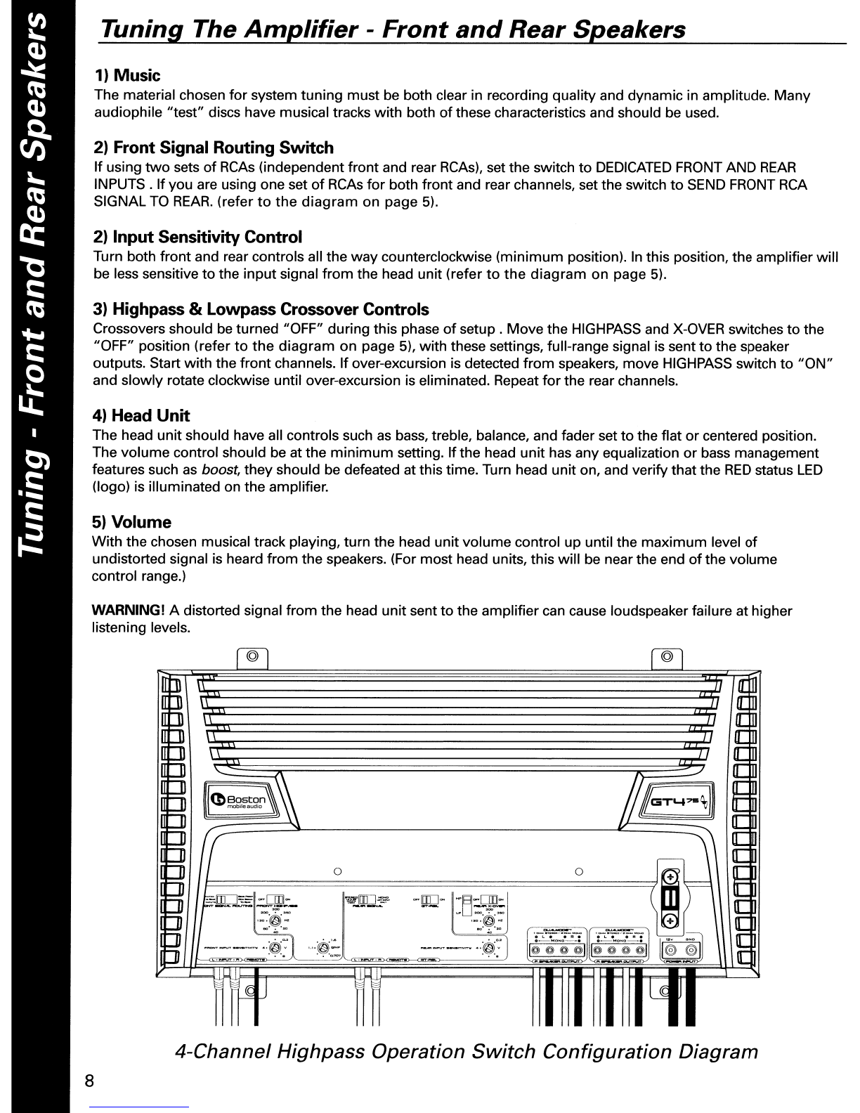
4-Channel Operation Wiring Configuration Diagram 9

Tuning The
Amplifier
-
Front
Speakers
and
Subwoofer
(s)
1)
Front
Signal
Routing
Switch
If
using
two
sets
of
RCAs (independent
front
and rear RCAs), set the switch
to
DEDICATED FRONT AND
REAR
INPUTS.
If
you are using one set
of
RCAs
for
both
front
and rear channels, set
the
switch
to
SEND FRONT
RCA SIGNAL TO
REAR.
(refer
to
the
diagram on page
5).
2) Head
Unit
The head
unit
should have all
controls
such
as
bass, treble, balance, and fader set
to
the
flat
or
centered
position. The
volume
control
should be at the
minimum
setting.
If
the
head
unit
has any equalization
or
bass
management
features such as boost,
they
should be deactivated at
this
time. Turn head
unit
on, and
verify
that
the
RED
status
LED
(logo) is
illuminated
on the amplifier.
3)
Volume
With
the chosen musical track playing,
turn
the head
unit
volume
control
up
until
the
maximum
level
of
undistorted
signal is heard
from
the speakers. For
most
head units,
this
will
be
at
the
end
of
the
volume
control
range.
WARNING! Adistorted signal
from
the head
unit
sent
to
the
amplifier
can cause speaker failure at
higher
listening levels.
4)
Input
Sensitivity
Control
(Front and Rear Channels)
Turn
control
(refer
to
the
diagram
on page
5)
all
the
way
counterclockwise
(minimum
position). In
this
position,
the
amplifier
will
be less sensitive
to
the
input
signal
from
the
head unit.
Slowly
rotate
this
control
clockwise until
maximum
undistorted playing level is heard
from
the
subwoofer(s). Listen closely
for
faults
such
as
bottoming
from
the
subwoofer(s).
If
fault
is detected, rotate
input
sensitivity
control
counterclockwise
until
fault
is eliminated.
At
this
point,
the
maximum
undistorted
subwoofer
playing level has been defined.
5)
Highpass Crossover
Control
(Front Channel Only)
To
achieve
higher
undistorted
playing levels
from
the
front
speakers,
the
highpass crossover
must
be
engaged. Rotate
the
crossover
control
fully
clockwise (refer
to
the
diagram
on page
5).
The highpass
crossover
point
is
now
set at 350Hz. Rotate ''Q-Tune™II Control
fully
counterclockwise.
Move
crossover
switch
to
the
right
(ON) position.
I©l
I©l
r;]
~
\,
~
~
f;;;;
F\
==
=
'-
./
=
df~~%11
in=
11~ea-\~
~
n~
mobile
audio
t;::
~'( ~
=
;::
=0
om=
==
~
FJIO:'::=
-DlJI-
'?£f~
-IW.:)-
".~=-cw:.
;::
-----
==~
..
:~~:
~
,~~'i:
=
=
"",,0.
'..,
"";.,°.
0
;::
51
I-~--Ig~
o
L.
0
It
•0
L.
0
It
•
:;
1/-:-:---
..
~:
,,,~::.
--_.~.
":$:'
II~
~O"~ @1ii1~~O"~
@I
I@
@I
:=
'.
·n...,.,
1-1
c-
...
IIf1It
~
~
Ul§
Bridged
Lowpass
with
Q-
Tune™
Switch
Configuration
Diagram
10

Tuning The
Amplifier
-
Front
Speakers
and
Subwoofer
(5)
11
-
-
+
)
3Channel Operation Wiring Configuration Diagram
••
••
e
e_
'-'--"-"'-"'_'--"-"''--''-'''.'--''-'''-'.'"'
: :
Setting the
Q-Tune™
control is done in conjunction
with
setting the levels on the
input
sensitivity and high-
pass crossover frequency controls.
You
may
find
while
setting the
Q-Tune™
that
over-excursion
may
be
detected in the
front
speakers;
lowering
the
Q-Tune™
input
sensitivity
or
raising
the
highpass crossover
point
will
eliminate this.
Minor
adjustments
to
each setting are required
to
fine-tune the system.
Highpass Crossover Control (Front Channel Only) Cont.
Slowly
rotate the
input
sensitivity control clockwise until
maximum
undistorted playing level is heard
from
the
speakers. Listen closely
for
bottoming
from
the speakers.
If
detected, rotate the
input
sensitivity control
counterclockwise until
it
is eliminated.
Slowly
rotate the highpass crossover control counterclockwise
while
listening
for
bottoming.
You are lowering the crossover point, which means
that
more
bass signal is being
sent to the speakers.
If
bottoming
is detected, rotate the
input
sensitivity control counterclockwise until
it
is
eliminated and/or rotate the Highpass crossover control clockwise
to
raise the crossover point.
6)
Q-Tune™Control (Front Channel Only)
Once the highpass crossover
point
has been determined, use the
Q-Tune™
control (refer
to
the diagram on
page
5)
to
increase the bass
information
centered around the crossover point.
Setting the
Q-Tune™
is asubtle process. It is recommended
that
the
Q-Tune™
setting
be
left in the 0.7 position
and adjusted
only
after the
input
sensitivity and highpass crossover ranges are known. Small adjustments
to
the
Q-Tune™
setting are all
that
are required
to
fine-tune the system.
7)
Rear
Input
Switch
For dual
RCA
Input, set switch
to
STEREO.
If
one
RCA
is used,
move
switch
to
the right-hand (MONO) position
(refer
to
the diagram on page
5)
8)
Lowpass Crossover Control (Rear Channels Only)
Move
the selector switch
to
"ON"
(refer
to
the diagram on page
5).
In
this
setting, lowpass signal is sent
to
the
speaker outputs. Experiment
with
the crossover
point
settings
while
the
subwoofer
is active. Ahigher setting
will
increase the perceived output, and a
lower
setting
will
make the bass response
more
omnidirectional.
9)
RSL
Control (Rear Channels Only)
The remote level control (GT-RSL) gives you independent level adjustment
of
the subwoofer's
output
level
beyond the standard system
volume
control. Please refer to the
RSL's
manual
for
installation instruction. The
GT-RSL is available separately, please consult
your
authorized Boston Acoustics dealer.

Amplifier Troubleshooting Guide
Status
LEOs
on
Amplifier
not
Lit-Head
Unit
(Source) Turned
"ON"
Verify Remote
turn-on
wire
from
source
to
amplifier
has
proper
voltage
Power (B+) connections at amplifier, terminal blocks, and battery are secure
Ground (GND) connections at
amplifier
and vehicle chassis are secure
Battery
B+
fuse and
amplifier
fuse are OK
B+
at battery and
B+
at
amplifier
have
proper
voltage
Status
LEOs Lit,
no
Output
from
Speakers-Speakers
in
Normal
Operating
Condition
Verify High-level cables
from
speaker(s)
to
amplifier
are securely connected
RCA
cables
from
amplifier
to
source are securely connected
Sensitivity
adjustment
on
amplifier
is correctly adjusted
Engine Noise
from
Speaker(sl
Turn source "OFF" and disconnect
RCA
cables at
amplifier
If
noise stops, check
equipment
and cables leading
to
amplifier
Verify
RCA
cables are
of
good
quality
with
no breakage
to
internal shields
RCA
cables
from
source
to
amplifier
are
not
run alongside
power
Amplifier
Output
Distorted-Music
not
Recorded
with
Intentional
Distortion
Verify Source
output
to
amplifier
is
not
distorted
Amplifier
input
sensitivity is correctly adjusted
Amplifier
Shutting
Down,
Red
Blinking
and Orange
LEOs
Lit-Amplifier
in
Thermal Protection
Mode
Verify
Amplifier
is
mounted
with
adequate air circulation around vents
Amplifier
does
not
have obstructions blocking back
or
side panel vents
Amplifier
is
not
mounted
under
carpet
Speakers meet correct impedance
for
application
(mono
or
stereo hookup)
Amplifier
not
Turning
"ON",
Orange
LED
Lit-Amplifier
not
Connected
to
a
Shorted
Speaker
Verify Speaker crossover is
not
defective
High-level cables
from
speaker
to
amplifier
are
not
shorted
Amplifier
not
Turning
And
Both
LED
(s)
Blinking-Speakers,
Crossovers, and Cable OK
Internal fuse needs
to
be replaced
Verify Replace fuse
with
fuse
of
same value
Amplifier
not
Turning
"ON",
Orange
LED
Lit-Speakers,
Crossovers,
and
Cable OK
Amplifier
requires service
If
Service Seems Necessary
First, contact
the
dealer
from
whom
you
purchased
the
product,
or
contact us via e-mail at:
USA
and Canada:
Europe:
Japan:
Asia/Pacific countries: [email protected]
We
will
promptly
advise
you
of
what
action
to
take.
Boston
Acoustics, Inc. 300
Jubilee
Drive, Peabody,
MA
01960
USA
T:
978.538.5000
F:
978.538.5100 W:
bostonacoustics.com
Boston, Boston
GT,
Boston Acoustics,
and
the
Boston Acoustics logo are registered trademarks
and
DualMode
and
Q-Tune are trademarks of Boston Acoustics,
Inc.
Specifications are
subject
to
change
without notice. ©2008 Boston Acoustics,
Inc.
All
rights reserved. Covered by
patents
issued
and/or
pending. 142-003179-1
This manual suits for next models
1
Table of contents
Other Boston Mobile Audio Amplifier manuals