Bowaters MODELS BME-009 User manual
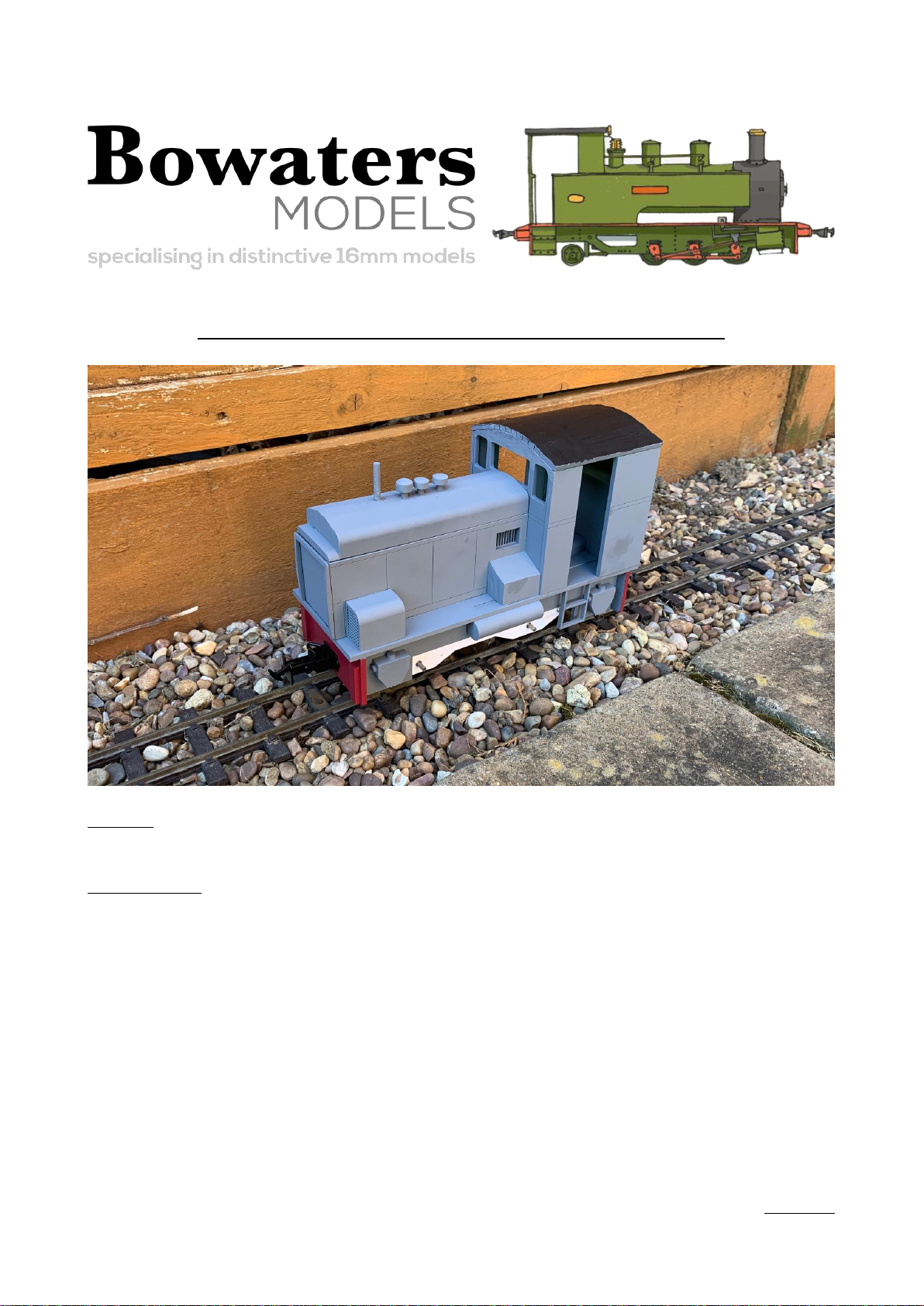
Bowaters Models –BME-009 Instructions
Requires
•Glazing Material
Required Tools
•Fine Sandpaper/Emery paper or boards
•Small Files
•PVA Glue
•Super Glue
•Sharp Craft Knife
Version 1.0

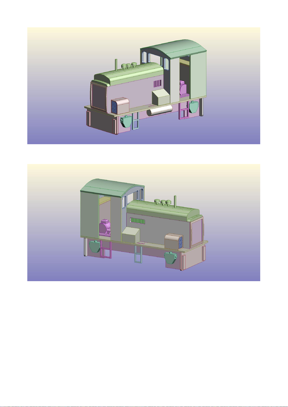
Prototype Information
‘Upnor Castle’was originally built for the Royal Navy for use on the Chattenden and Upnor
Railway in Kent in the mid 1950s. It entered preservation in the early 1960s at the Welshpool and
Llanfair Railway before moving the Ffestiniog Railway in 1968. The FR have rebuilt the engine
with a more powerful engine and extending the wheelbase. It is known on the railway as ‘Uproar’
due to the excessive amount of noise in the cab! It was transferred to the Welsh Highland Railway
in 1997 before returning to the FR in 2010. The engine is modelled in its post 2010 rebuild
condition.
About the Kit
The kit is a plastic kit comprising of a set of laser cut acrylic parts and 3D printed sections.
Chassis Fitting
This kit is designed for a PDF Models Chassis which is included as part of your kit. This is
assembled as per the instructions. Make sure the chassis works in the way you intend it before
fitting to the model. Note, this kit is designed for either Manual control using switches (single
speed) or using full Radio Control for which space has been left within the model.
Couplings
This kit is designed to make use of the Accucraft Chopper Couplings. These are glued onto the
buffer beams using superglue. We strongly recommend using superglue to attach them. Height wise,
these should be 25mm from the centre of the coupling plate to the railhead.
Instruction notes
With these instructions, there are images which show various stages of the construction of the kit
kits. They are of the digital test build for BME-009 which may not be representative of the kit you
have brought. They are for reference purposes only.
Painting
•Current paint scheme –Main Body- Brunswick Green and Black with red lining. Chassis –
Red Bufferbeams and Black chassis.
Please Turn over
Please read though these instructions before beginning to assemble your
kit
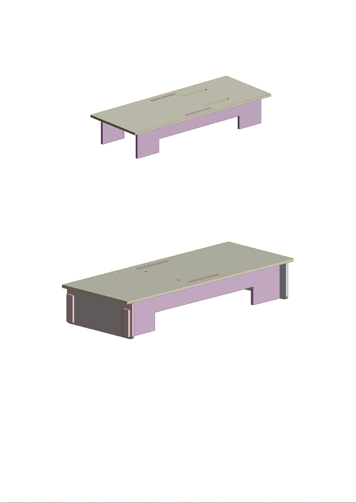
Start off by gluing the chassis side frames onto the floor plate.
\
Next, glue on the buffer beams. These sit on either end of the chassis with one having laser
engraved markings on it going on the end with the slots on.

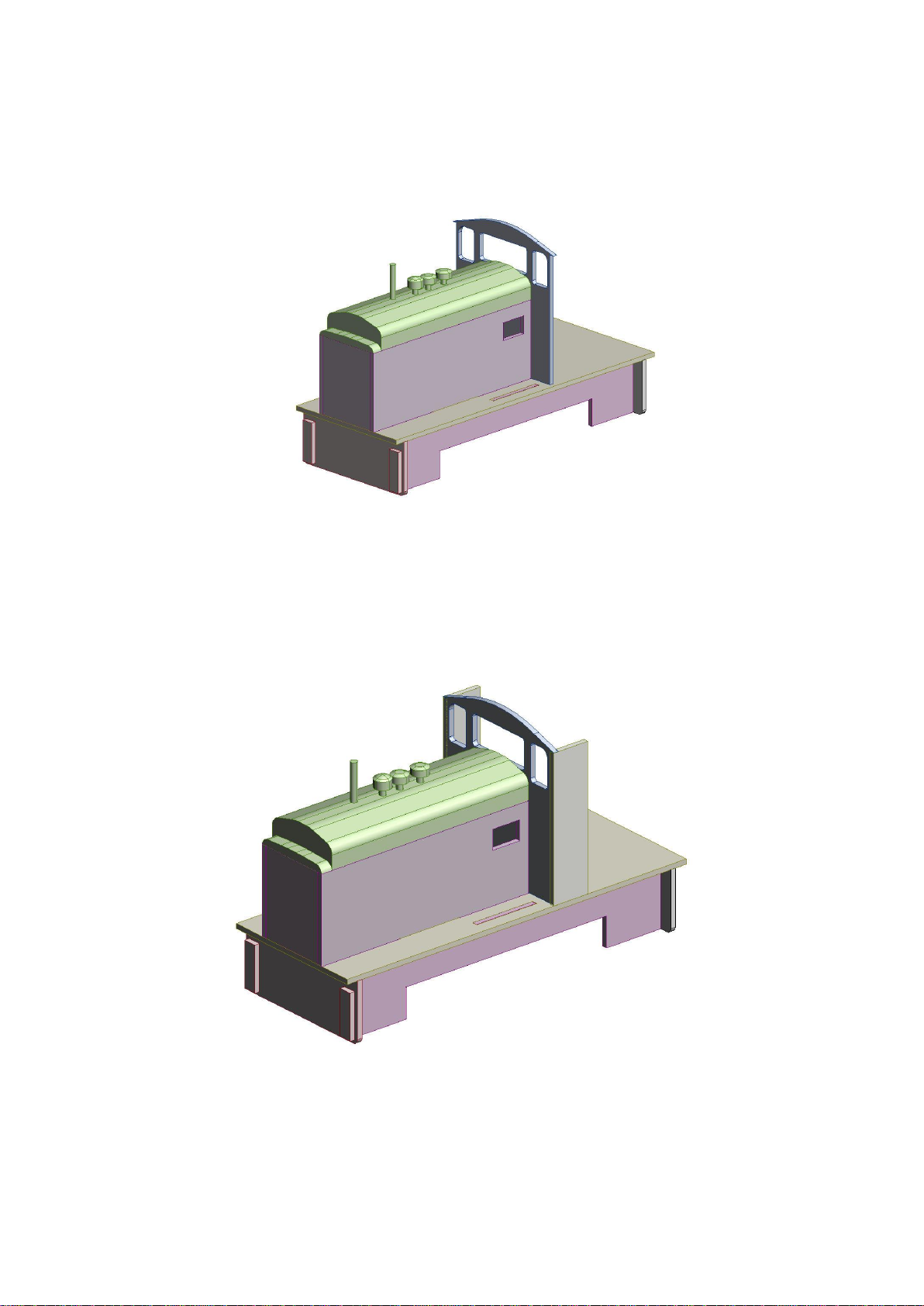
Next glue on the sides of the bonnet. These are handed because of the etched markings on the
model.
Next, glue on the front of the bonnet. This slots into the front of the bonnet.

Now glue on the front of the cab.
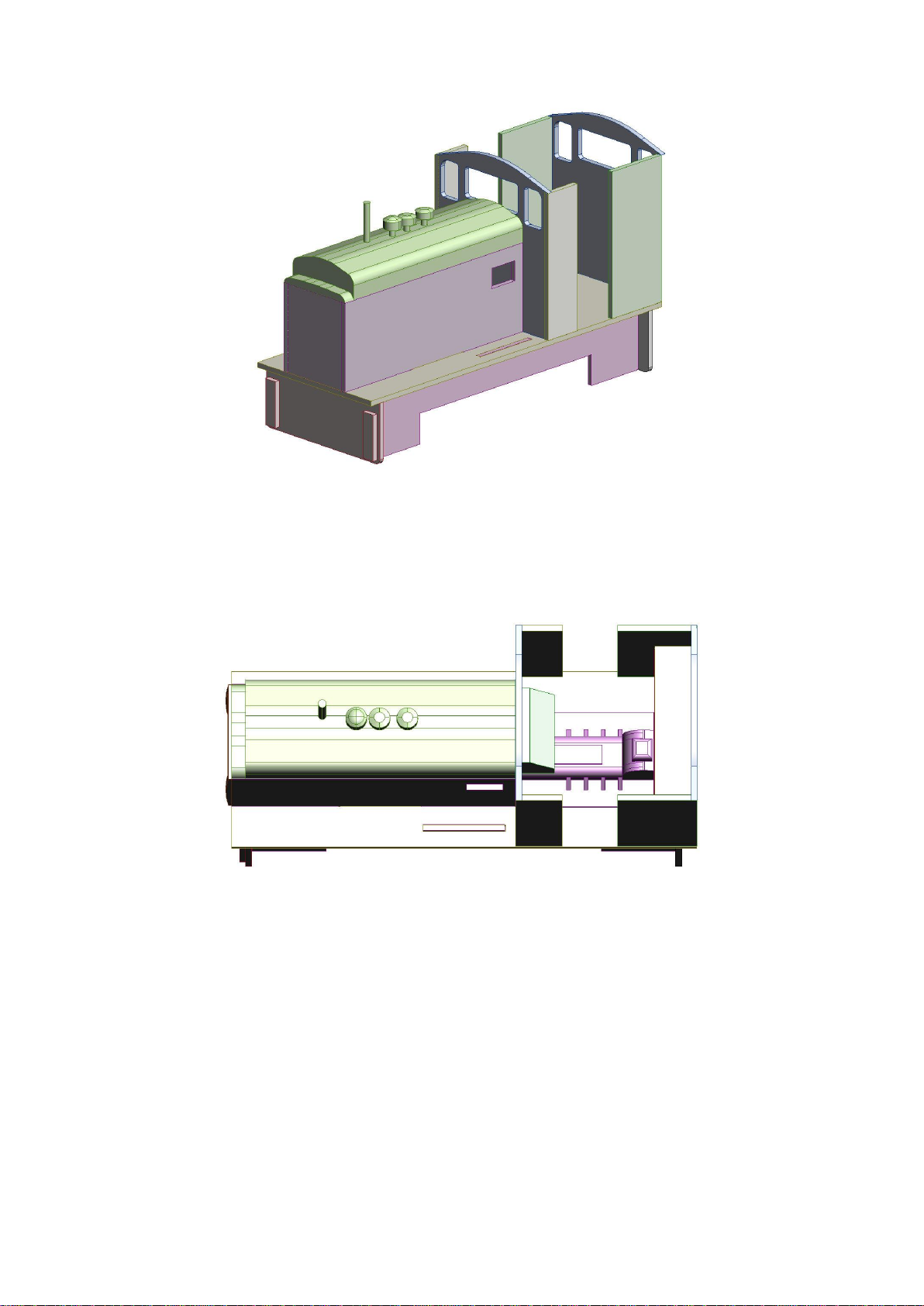
Now is a good time to glue in the grills. These sit on the insides of the bonnet on the relevant sides
of the bonnet.
Next, place on the bonnet top which sits over the top of the bonnet. This slots into place and gives
access to the batteries when the time is right. We recommend that you hold this in place with double
sided tape for easy access to the battery location.
Now start assembling the cab. Glue on the short sides of the cab which sit on the front of the cab.
Now glue on the rear of the cab and longer cab sections. These sit parallel with the rear of the
chassis.
Now it’s time to add the interior. The gearbox rests against the front of the cab with the dashboard.
The rear shelf slots in between the gearbox and the rear of the cab with the top section being glued
on top.

Now glue on the roof. The straight sections go on the flat sections of roof and the thin sections are
glued across the top of the roof.
Now glue on the equipment cases. These vary depending on when the engine was operating so its
best to reference against images of the engine for the time period you are modelling. We have shown
as the engine was operating in the 2010s.

On the fan covers, its best to insert the grills before gluing on the covers. These slot into the gaps on
the 3D printed part.
Here we show the right hand side. Note the different positioning of the fan cover compared to the
left hand side.
Now glue on the sandboxes and steps onto the model referencing against the real engine. On the left
hand side, there is a vacuum tank which is positioned in the middle of the frames.
Note the different positioning on the right hand side.
We hope you enjoy your Bowaters Models kit! If you have any questions, don't hesitate to contact
us on info@bowatersmodels.co.uk
We thank you for your custom.

Chassis Instructions
Start by laying out all the chassis parts to ensure you have everything.
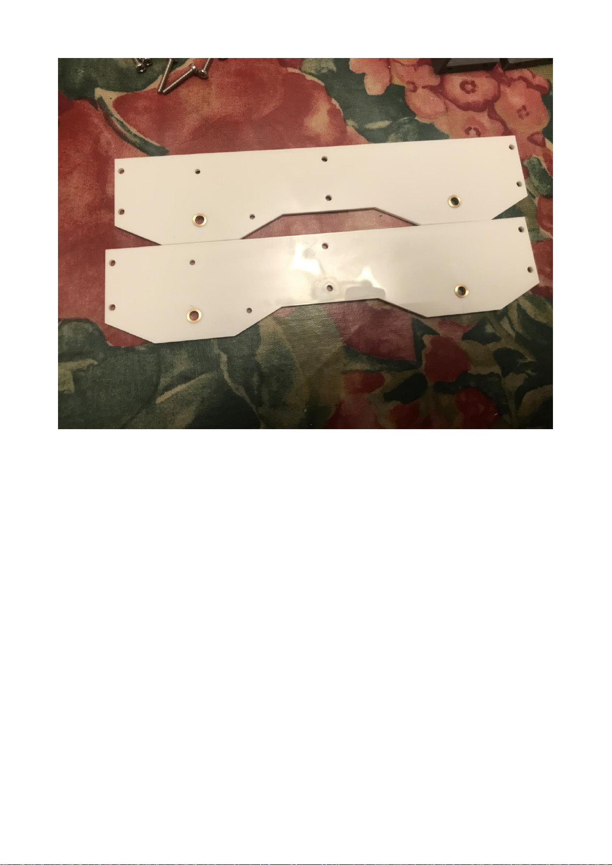
Start by placing the bearings with the chassis sides. You may need to open these out using a 4mm
drill bit.
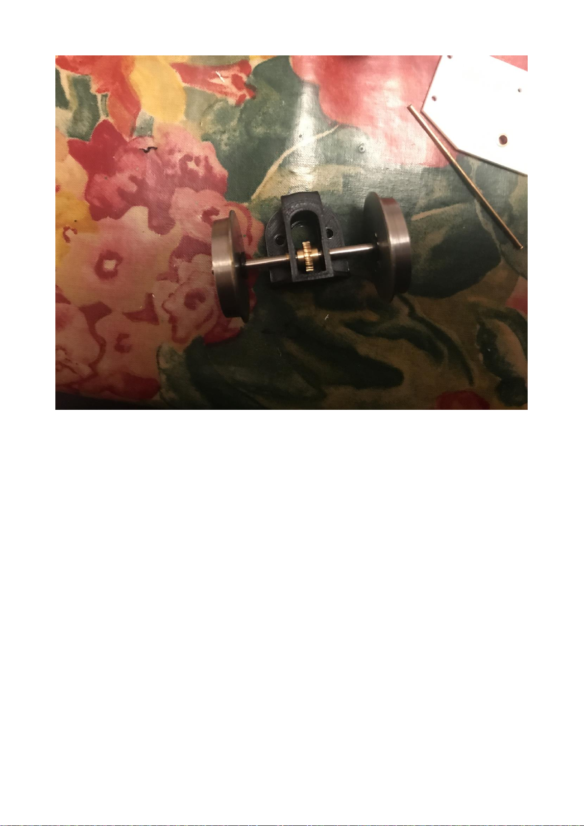
Next assemble the driving wheel set. The cog goes into the middle of the chassis inside the gearbox
housing. The axle will need cutting down if running on 32mm gauge (45mm gauge version shown).
This should be done once the chassis has been test assembled to know you have the right
dimensions. It is at this time you will want to add the gears for the 4w drive system while
assembling the wheelsets. The drive gear sits inside one of the wheels on each side and there is one
per wheelset.

Start inserting the chassis spacers starting at one end and working your way along the chassis.
Shown is the old style of chassis with 2 wheel drive. On the newer 4w drive models, it is
recommended that you turn the two end spacers so that the mounting holes are on the outsides of
the chassis ends.
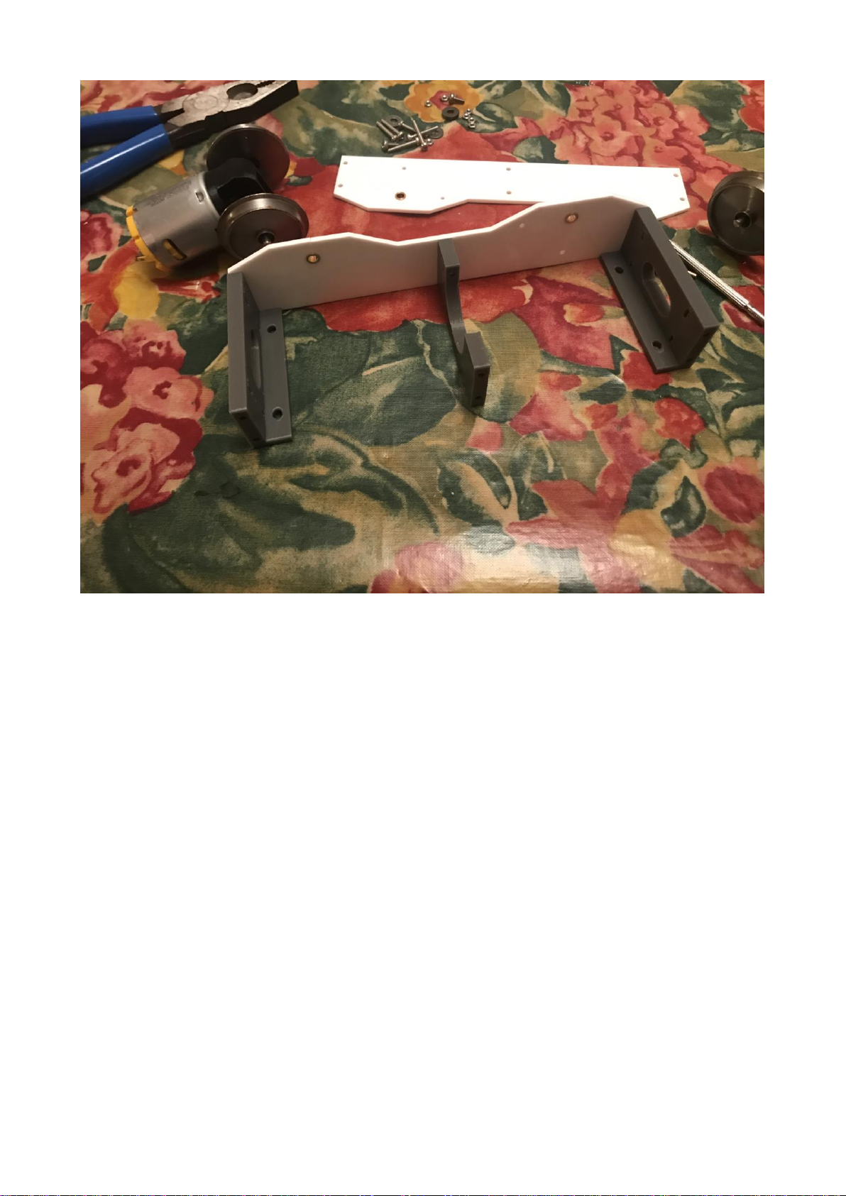
All 3 spacers shown on the chassis.
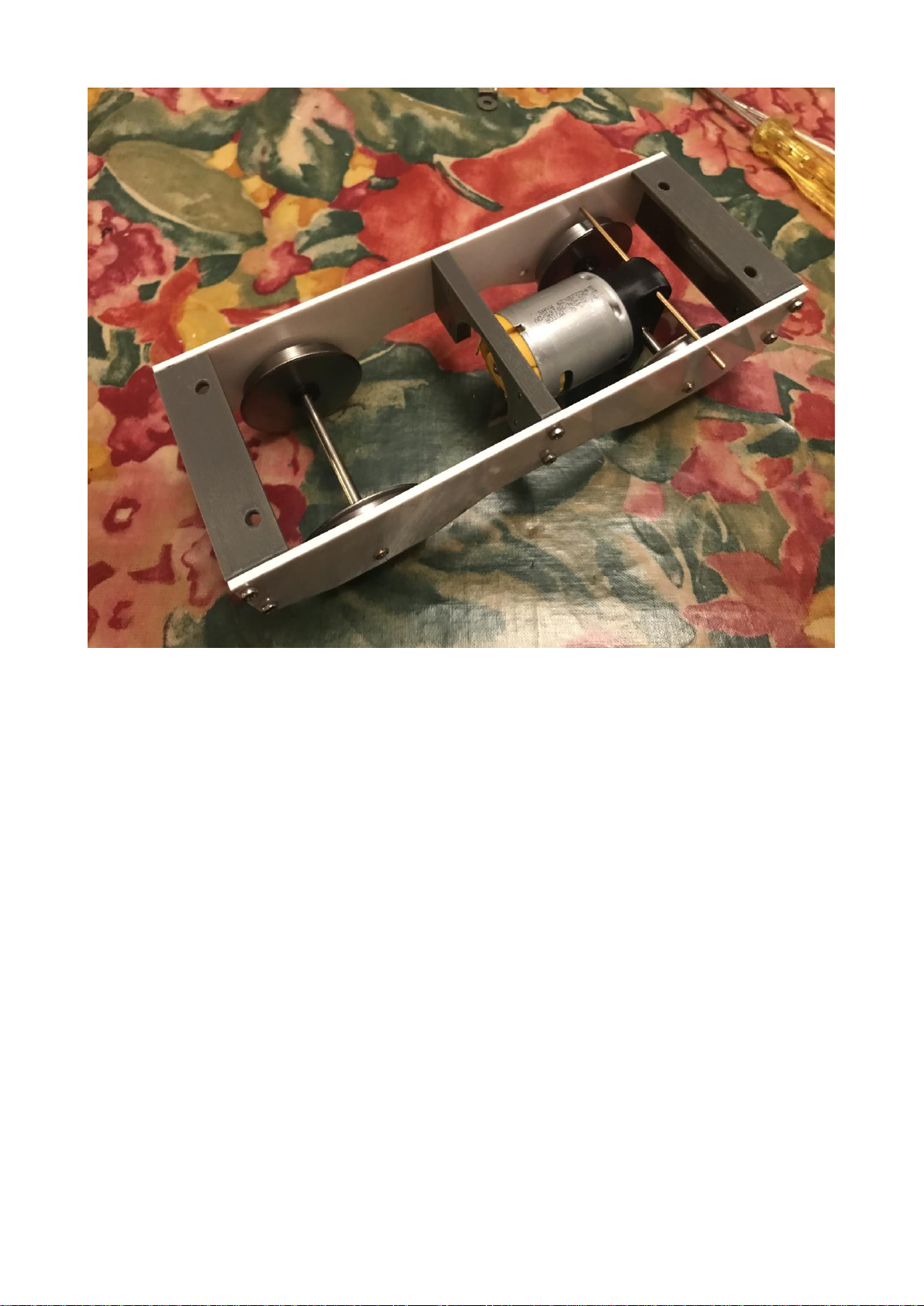
Now insert the wheelsets and the other chassis plate so you have a complete chassis.
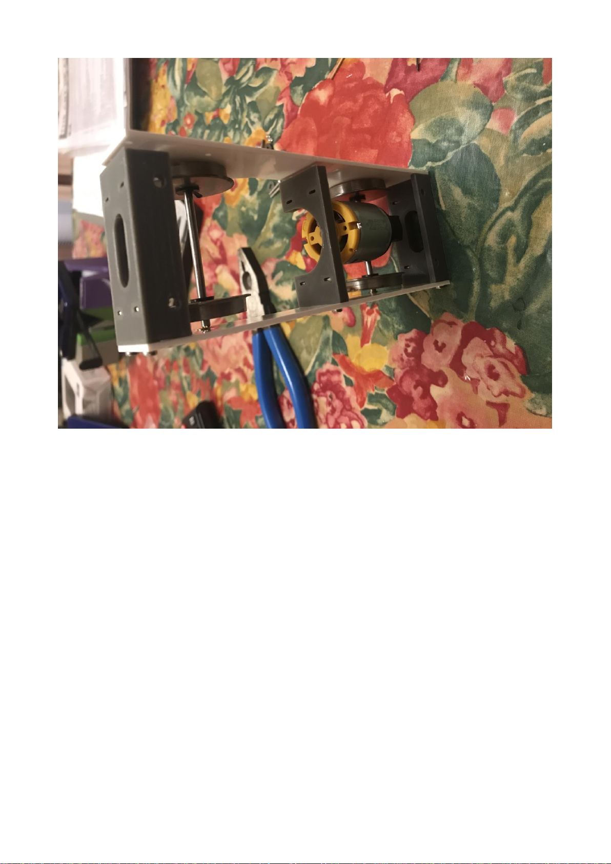
Now insert the retaining wire so your motor is held in place and won’t move. Shown above is the 2
wheel drive chassis. The 4 wheel drive chassis has the motor mounted vertically with the fixing
holes on the very end of the chassis.
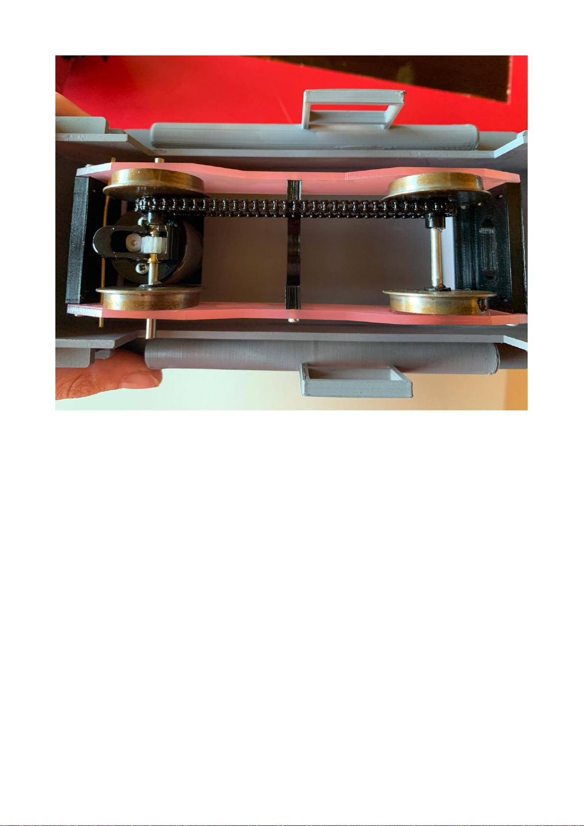
For the 4 wheel drive system, there is a cog on each wheel which sits on the inside of the wheels
between the gears and one of the wheels. The chain runs between the two wheel sets and should be
tight for maximum haulage ability
Your chassis is now complete except for wiring.
Table of contents
Popular Toy manuals by other brands


Faller
Faller Car Center Assembly instructions

Lionel Electric Trains
Lionel Electric Trains 390E Operation manual

Fisher-Price
Fisher-Price Lil' Music Makers 2-in-1 Bach ‘n Rock Guitar... instruction sheet

Carl Goldberg Products
Carl Goldberg Products Hot Stik ARF instructions

WARCRADLE STUDIOS
WARCRADLE STUDIOS DYSTOPIAN WARS ICE MAIDEN BATTLEFLEET Assembly instructions

marklin
marklin 21670 manual