70mm Spinner
.........................................................
.........................................................
.........................................................
.........................................................
.........................................................
.........................................................
.........................................................
.........................................................
.........................................................
.........................................................
.........................................................
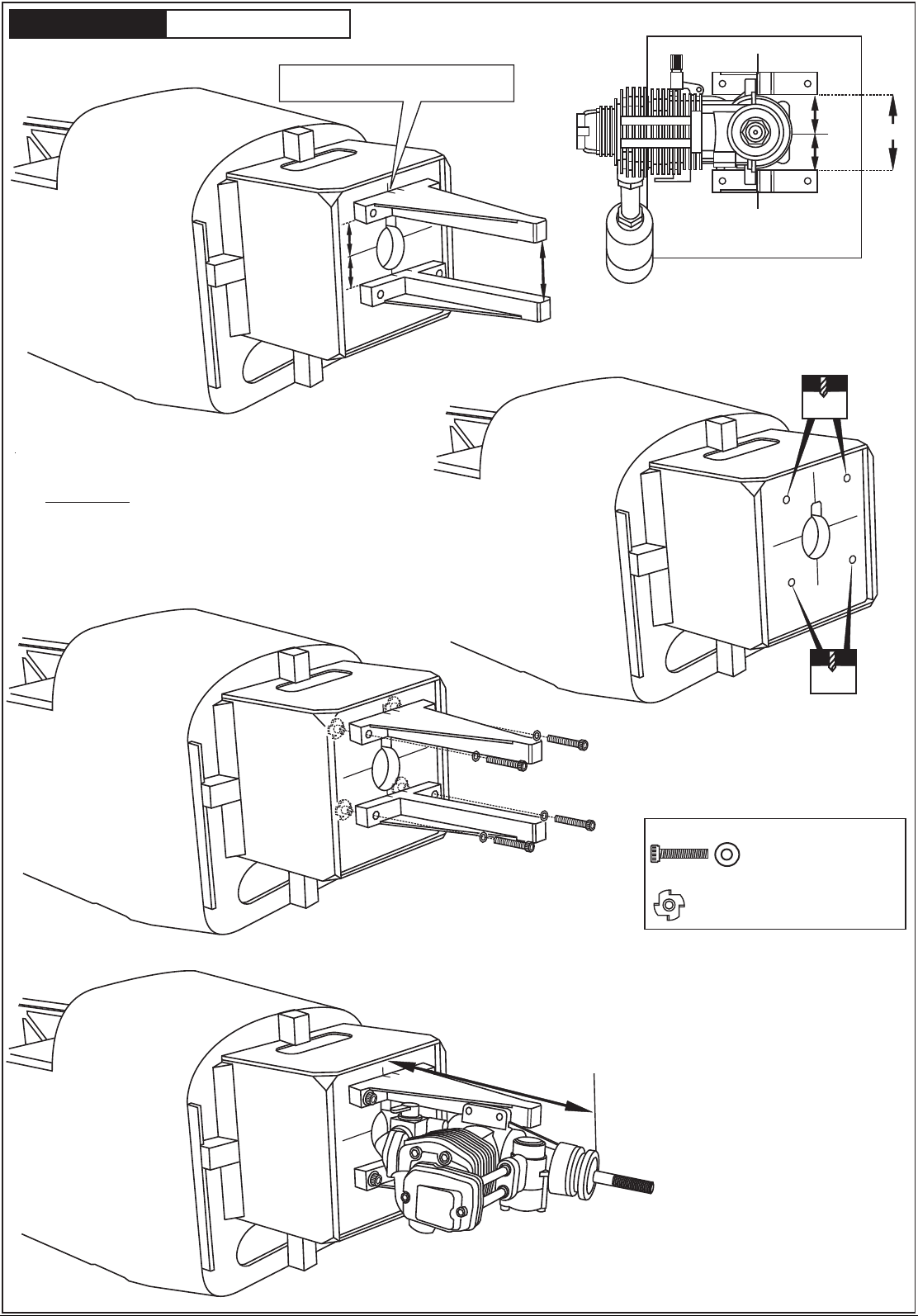
1.5mm
AB
!
CA
L/R
Assemble left and right
sides the same way.
X
Drill holes using the stated
size of drill
(in this case 1.5 mm Ø)
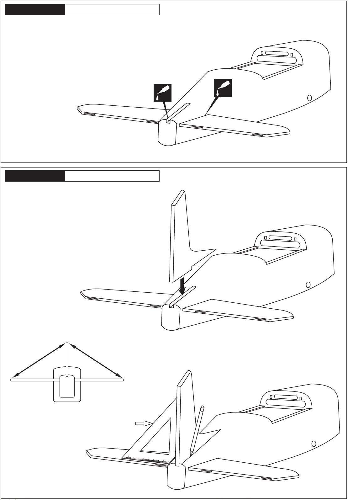
Use epoxy glue
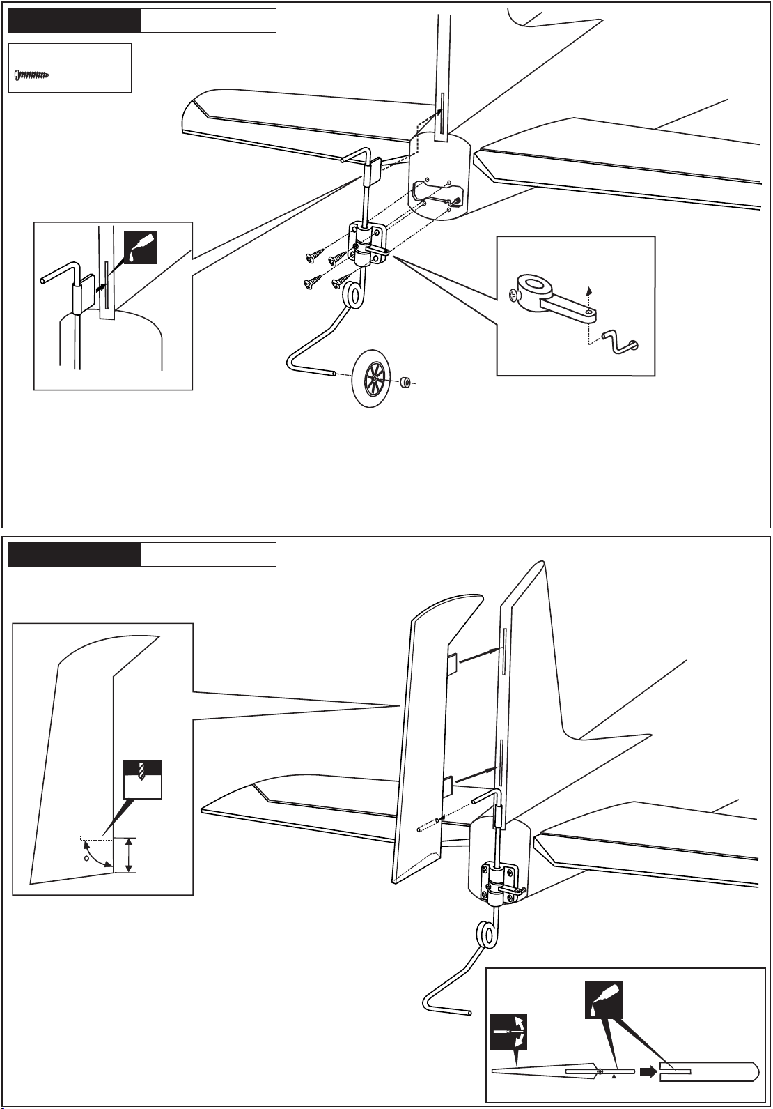
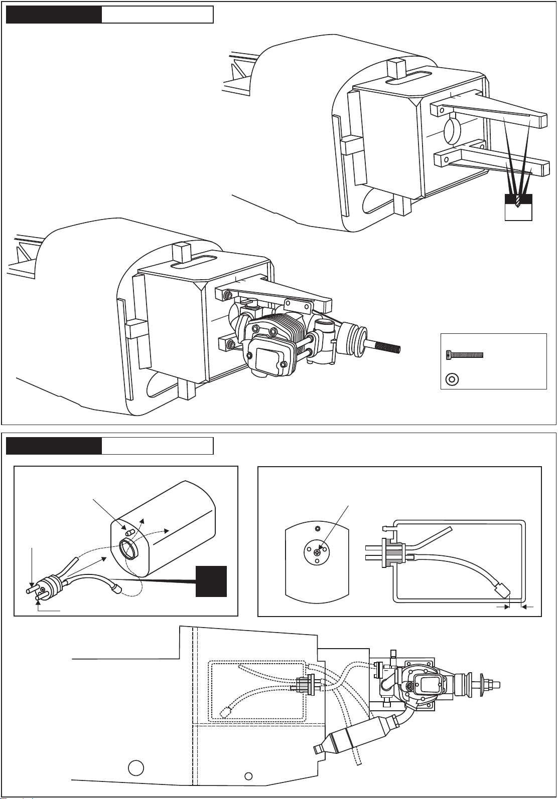
Take particular care here Hatched-in areas:
remove covering
film carefully
Not included.
These parts must be
purchased separately
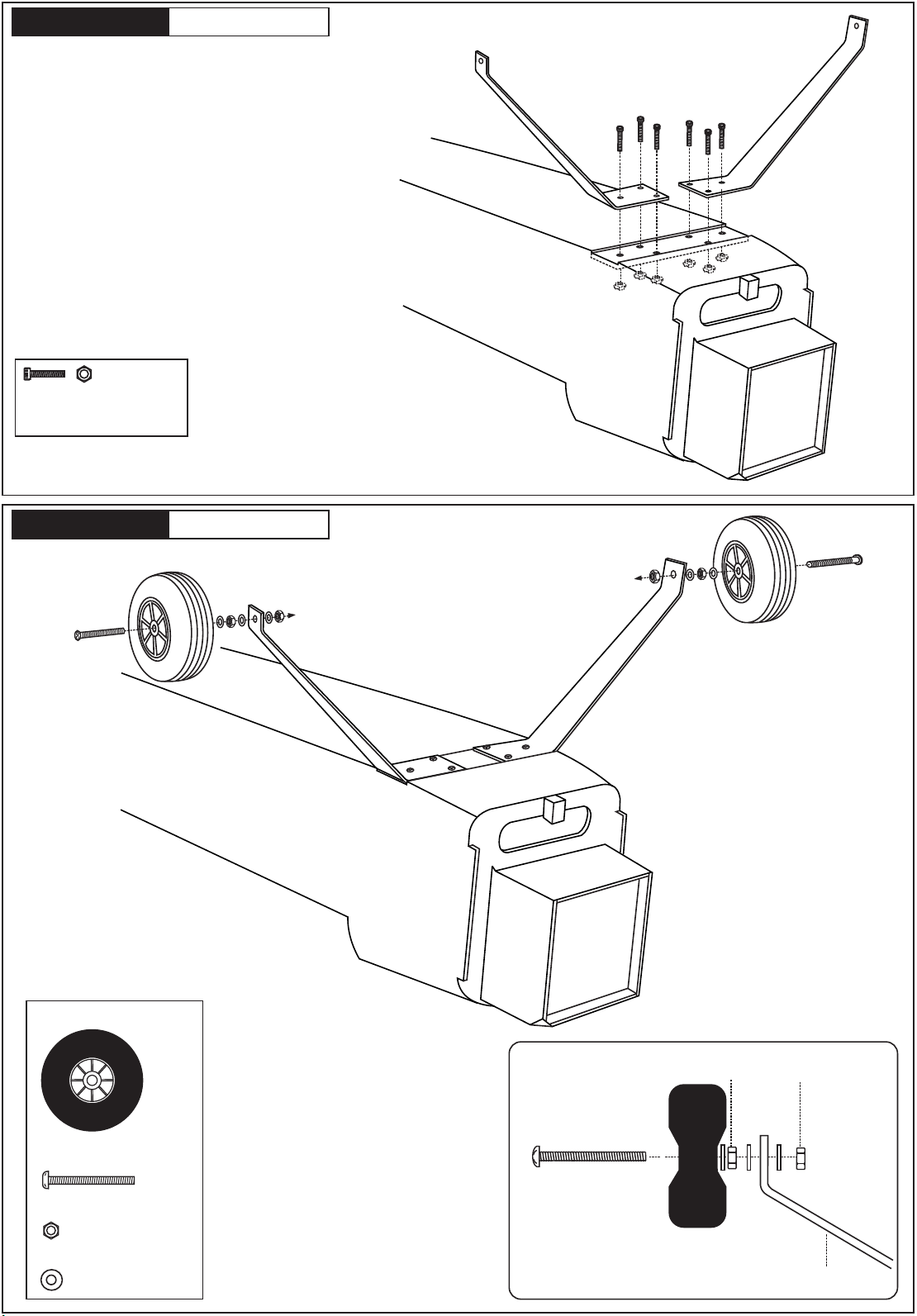
Check during assembly that these
parts move freely, without binding
Apply cyano glue
SILICON
EPOXY A
EPOXY B
CA
Epoxy Glue (30 minutes type)
Silicon Glue
Cyanoacrylate Glue
Sekundenkleber
Epoxy-Klebstoff (30min)
Minimum 6 channel radio
for airplane
.90 cu.in (8.5cc)
Extension cord
.60 cu.in. (7.5cc)
REQUIRED FOR OPERATION (Purchase separately)
Minimum 6 Kanal
Fernsteuerung
Servoverlangerungskabel
BENOTIGTE KOMPONENTEN (Nicht im Lieferumfang enthalten)
Brushless Motor
900-1000Watt
Brushless ESC
Brushless Regler
Silikonkleber
Tool Required/ Erfoderliches Werkzeug
CONVERSION TABLE
1.0mm = 3/64”
1.5mm = 1/16”
2.0mm = 5/64”
2.5mm = 3/32”
3.0mm = 1/8”
4.0mm = 5/32”
5.0mm = 13/64”
6.0mm = 15/64”
10mm = 13/32”
12mm = 15/32”
15mm = 19/32”
20mm = 51/64”
25mm = 1”
30mm = 1-3/16”
45mm = 1-51/64”
If exposed to direct sunlight and/or heat, wrinkles can appear. Storing the
model in a cool place will let the wrinkles disappear. Otherwise, remove
wrinkles in covering film with a hair dryer, starting with
low temperature. You can fix the corners by using a hot iron.
Bei Sonneneinstrahlung und/oder Wärme kann die Folie erschlaffen bzw. Falten
entstehen. Verwenden Sie ein Warumluftgebläse (Haartrockner) um evtl. Falten aus der Folie
zu bekommen. Die Kanten können Sie mit einem Bügeleisen behandeln. Nicht zuviel Hitze anwenden ! Low seting
www.motionrc.com