BOWE P 240 User manual
P 240 P 300 USA
P 300 P 350 USA
Installation Instructions
IA. P 240 /P 300 / /09.01 /E IV
SN 703868
IP240e0901

This machine, which works with the solvent
tetrachloroethane (perc), complies with the
EC Machinery Directive 98/37 EC,
the EC Low Tension Directive 73/23 EEC
as amended by RL 93/68 EEC, EMV-recommendation
according to EN 55022 and ENV 50140 and the
Harmonised Standards:
EN 292 Part I and Part II
EN 60204-1 (DIN-VDE 0113 Part I)
EN 418
EN ISO 8230*
The contents are correct to the best of our
knowledge and belief and correspond to the
present level of technology. No legal claims
can be derived.
Technical modifications reserved.
Reproduction or duplication only with our
express premission.
* with options: -post separator and
-overfilling sensor still

Necessary operation items and chemical additives
Dear customer,
At the time your dry-cleaning machine P 240 (P 300 USA)
P 300 (P 350 USA) will be installed please make sure that the following
items are available:
-Solvent
It is only allowed to use TETRACHLOROETHANE (perc) stabilised, high
purity, according to DIN 53978.
Total filling amount for the first filling: P 240 (P 300 USA): 220 l (360 kg)
P 240 (P 300 USA): 58.1 USgal (794 lb)
P 300 (P 350 USA): 260 l (420 kg)
P 300 (P 350 USA): 68.7 USgal (926 lb)
Tank I: min. filling volume: P 240 (P 300 USA): 60 l (15.9 USgal)
P 300 (P 350 USA): 70 l (18.5 USgal)
-Chemical additives
Chemical additives with thermal stability under operation conditions must be
used.
Depending on the equipment the following should be available:
-cleaning aids
-antistatic agent
-waterproofing
-pre-and post spotting
BÖWE Textile Cleaning GmbH
Rumplerstraße 2, D-86159 Augsburg
Telefon (08 21) 57 07-0, Telefax (08 21) 57 07-351
Phone: ++49-821-5707-0, Fax: ++49-821-5707-351
email: vertrieb@boewe-tc.de

P240 IA
1
Dear Customer,
It gives us great pleasure to supply you with
your BÖWE machine.
In designing and building it we have attached
great importance to quality. It is up to the
latest level of research and technology.
Please do not put this installation instructions aside
unread!
These instructions contain important information on
operational details of your drycleaning machine.
If the specified maintenance work is neglected or carried out
inexpertly,repair work is not carried out by service technicians authorized
by BÖWE and no original BÖWE spare parts are used, we cannot meet
the warranty obligations contained in our General Terms of Delivery.
Measurements and other values are as at printing
date.
We reserve the right to make technical changes
without prior notice in the interest of further
development or required constructional
modifications.
Reproduction -including excerpts -is only
permitted with prior written approval and
acknowledgements.
BÖWE Textile Cleaning GmbH
Rumplerstraße 2, D-86159 Augsburg
Telefon (08 21) 57 07-0, Telefax (08 21) 57 07-351
Phone: ++49-821-5707-0, Fax: ++49-821-5707-351
email: vertrieb@boewe-tc.de

2
Table of contents
Page
1. General information 4
2. Machine side profile 5
3. Transportation 6
3.1 Entry 7
4. Foundation
4.1 Foundation measurements
Slimline 8
Crossline 9
4.2 Anchoring 10
4.3 Noise or vibration insulation 10
5. Machine fixing
5.1 Machine trough 11
5.2 Anchoring methods 11
5.3 Cemented-in stone bolts 12
5.4 Safety expanding anchors 12
5.5 Threaded rods (bored-through ceiling) 12
5.6 Adhesive plugs /shear connector 13
6. Installation
6.1 Surrounding conditions 14
6.1.1 Regulations 14
6.1.2 Temperature 14
6.1.3 Structural surroundings 14
6.2 Place of installation 15
6.2.1 Required space
Slimline 15
Crossline 16
6.2.2 Machine dimensions 17
6.3 Floor load 17
6.3.1 Dimensions 17

3
Table of contents
Page
7. Connection
7.1 Machine dimensions specification
Slimline 18
Crossline 19
7.2 Machine connections specification
Slimline 20
Crossline 21
7.3 Piping 22
7.3.1 Steam 22
7.3.2 Condensate 22
7.3.3 Cooling water supply 23
7.3.3.1 City cooling water connection 23
7.3.3.2 Cooling tower operation 23
7.3.3.3 Other cooling water save devices 24
7.3.4 Cooling water outlet 24
7.3.5 Contact water 24
7.3.6 Compressed air 24
7.3.7 Venting ducts 24
7.3.8 Electric connection 24
7.3.9 Actuation of room ventilation 28
8. Important hints
8.1 First start-up 29
8.1.1 Filling the machine with solvent 29
8.1.2 Replenishing solvent 30
8.2 Refrigeration unit 30
9. Technical data
9.1 P 240 with /without Slimsorba 31
P 300 USA with /without Slimsorba 33
9.2 P 300 with /without Slimsorba 35
P 350 USA with /without Slimsorba 37
10. Setting and optimal operating values 39
11. Safety hints 41

4
1. General information
Technical literature
We make reference to the publications and leaflets by the trade and professional
associations as well as research institutes and the safety data sheets of the
solvent producers.
Laws and regulations
All regulations concerning the industry, particularly with regard to proper handling of the
solvent TETRACHLOROETHANE (Perc), have to be met absolutely in order to avoid health risks
and environmental damage.
In any case please observe applicable laws and regulations in your country.
The machine meets the following requirements:
-EC Machinery Directives 98/37 EC
-EC Low Tension Directive 73/23 EEC as amended by RL 93/68 EEC
-EMV-recommendation according to EN 55022 and ENV 50140
Applied harmonised standards:
-EN 292 Part I and Part II
-EN 60204-1 (DIN-VDE 0113 Part 1)
-EN 418
-EN ISO 8230*
Applied German Standards and Regulations:
-VBG 20 -Safety Regulations for Refrigeration Equipment
Heatpumps and Refrigeration Plants
-Pressure Vessel Regulations
-CFC -Halon Prohibition Decree
Please observe the specific rules and regulations of your country.
Repair work
Please consult the BÖWE customer service organisation for all maintenance and
repair work as well as operating safety aspects of this high-quality drycleaning machine.
If required, the BÖWE service organisation will use original spare parts.
Safety
Safety devices may not be bypassed, switched off or otherwise be made
inoperative. In case of repair work or first start up please observe applicable
industrial safety rules.
Disposal of still residues and processing water must be carried out according
to the laws and regulations in your country.
*with options: -post separator
-overfilling sensor still
!

5
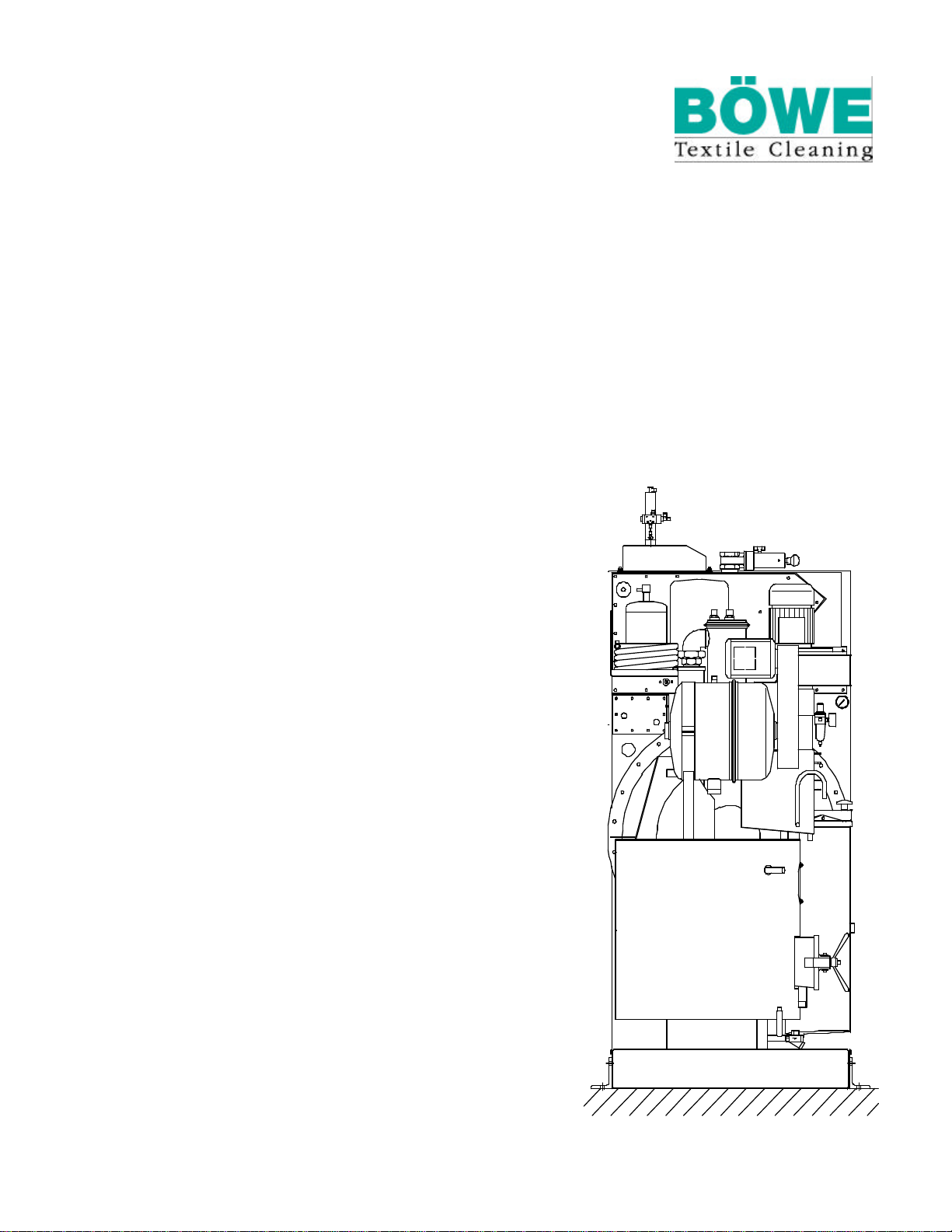
2. Machine side profile
Slimline
1Control box 10 ECO-filter
2Loading door 11 Filter drive
3Cage 12 Adsorption cartridge filter*
4Tanks 13 Condenser
5Solvent pump 14 Refrigeration unit
6Cage drive 15 Fan
7Lint filter /button trap 16 Recovery section
8Still 17 Solvent safety trough
9Water separator
*Option USA-Standard
6
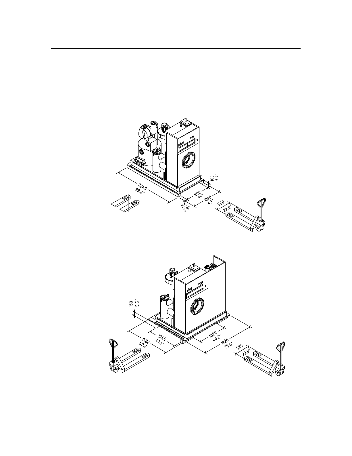
3. Transportation
For proper transportation, installation and connection it is recommended to consult
the appropriate experts in order to guarantee a damage-free handling.
For unloading transportation, machine entry and installation it is necessary to use suitable
tools and devices such as a crane, forklift, elevating truck, bottle lift, ropes, winch,
crowbars, rollers, wooden blocks, wedges.
Attention: Pay attention to center of gravity of the machine and secure against lateral tilting.
Slimline
Minimum width of the low lift platform truck 580 mm/22.8 inch!
703868-21-A
Crossline
Minimum width of the low lift platform truck 580 mm/22.8 inch!
703868-22-A

7
3. Transportation
3.1 Entry
Normally the machine is transported and entered in upright
position in a wooden crate or box.
Packing dimensions
Slimline Crossline
P 240 /P 300 USA P 240 /P 300 USA
P 300 /P 350 USA P 300 /P 350 USA
_______________________________________________________________________________
Width mm 1150 inch 45.3 mm 1970 inch 77.6
Depth mm 2290 inch 90.2 mm 1640 inch 64.6
Height mm 2250 inch 88.6 mm 2250 inch 88.6
Entry dimensions after unpacking
(Flaphousing and pipework part of cool-down are dismanteled)
_______________________________________________________________________________
Width mm 1080 inch 42.5 mm 1840 inch 72.4
Depth mm -inch -mm 1400 inch 55.1
Height mm 2010 inch 79.1 mm 2010 inch 79.1
Dimensions with dismanteled channel line of the trough
_______________________________________________________________________________
Width mm 955 inch 37.6 mm 1715 inch 67.5
8
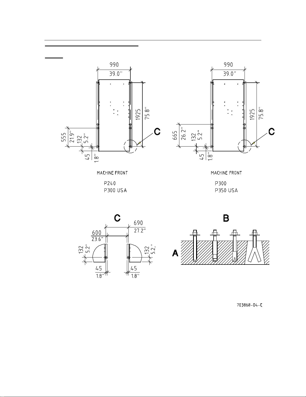
4. Foundation
4.1 Foundation measurements
Slimline
AReinforced concrete: For armoured floors directly on bearing grounds min. 100 mm (3.9 inch)
deep. At rooms with basement an static calculations engineer must be asked.
BExamples for machine fixing
CDistance from machine to next machine
9
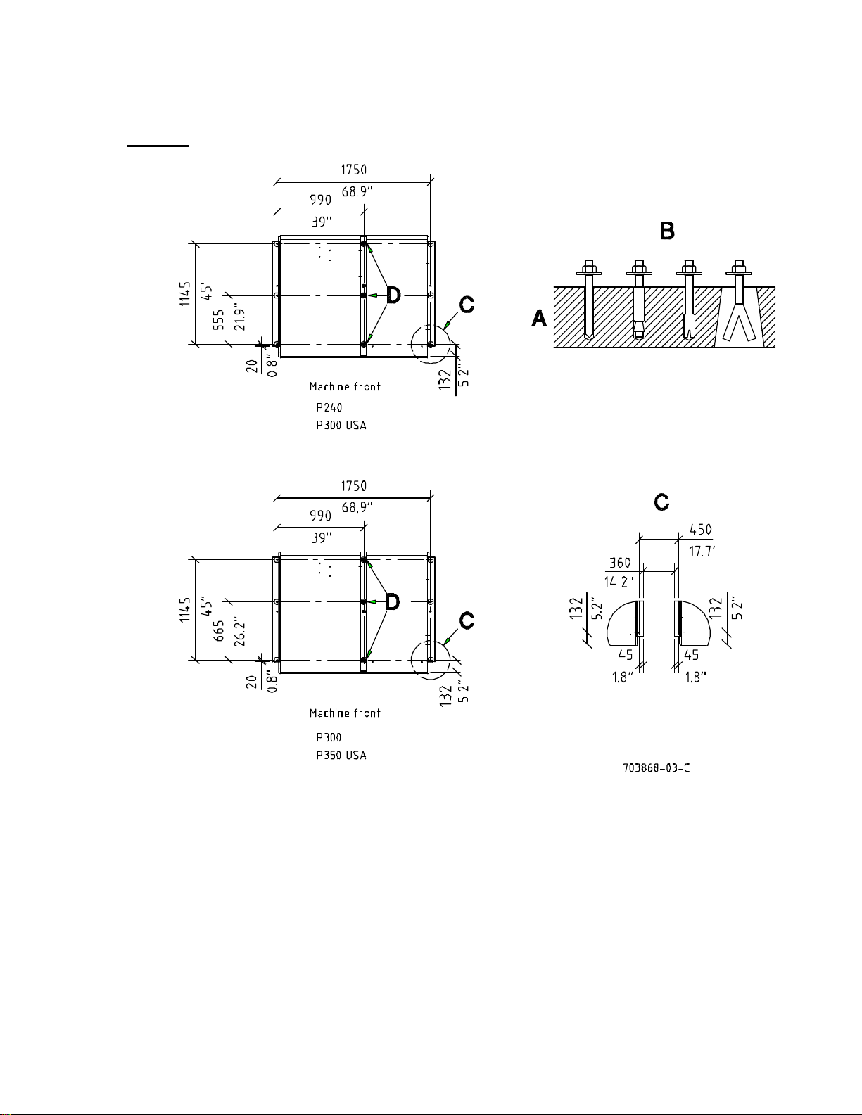
4. Foundation
Crossline
AReinforced concrete: For armoured floors directly on bearing grounds min. 100 mm (3.9 inch)
deep. At rooms with basement an static calculations engineer must be asked.
BExamples for machine fixing
CDistance from machine to next machine
DUse foundation anchors M12 x 300
10
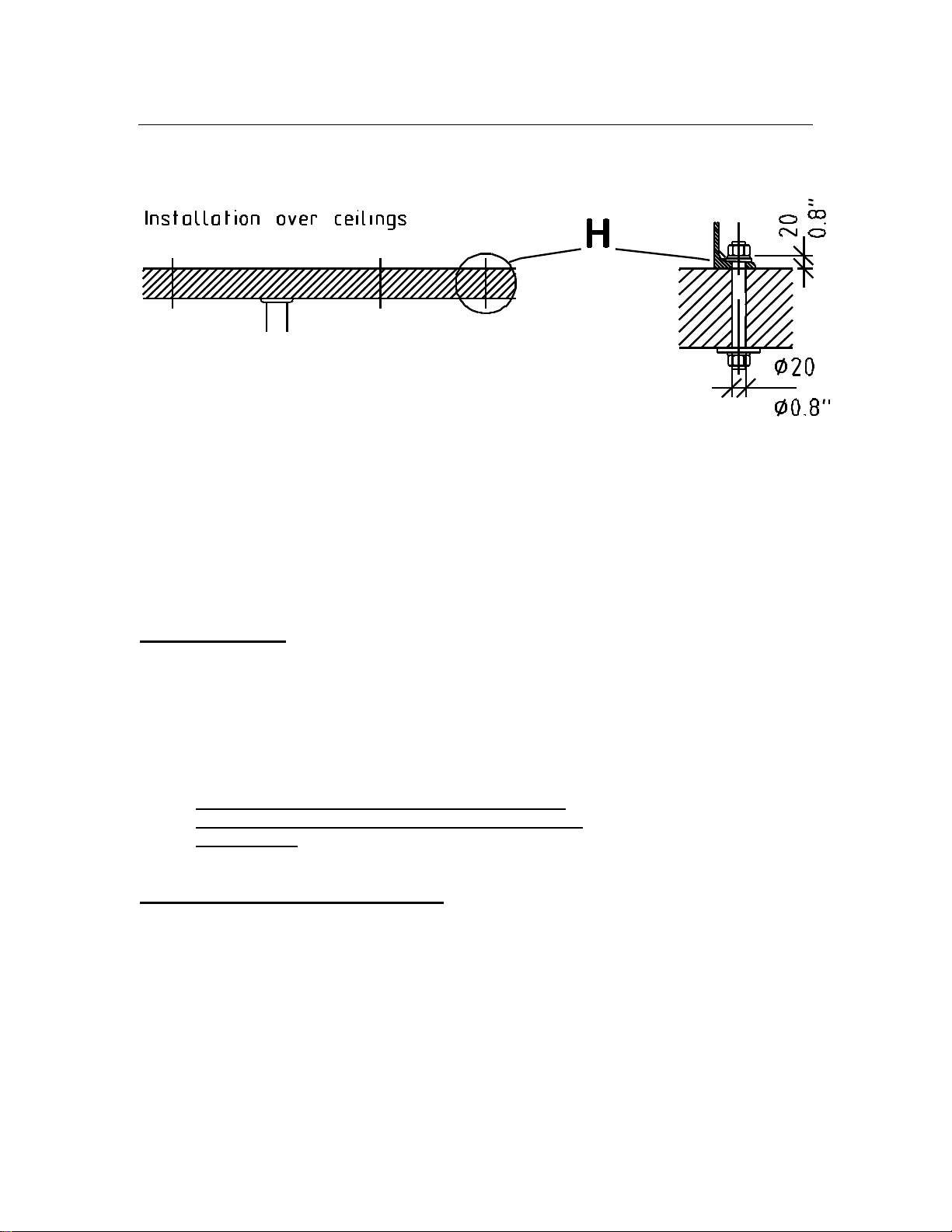
4. Foundation
703871-22-0
Ceiling borehole 20 mm (3/4 inch) ø for through-bolts, length H
depending on thickness of ceiling.
Support if necessary.
4.2 Anchoring
Correct anchoring is very important for low-noise, fault-free
operation. For installation on foundation it is preferable to
use stone bolts!
Seating must be horizontal and level. Do not place machine
directly on tiles, felt, bituminous coatings, rubber or cork.
With uneven concrete floors it is necessary to level the
machine with wedges and fill the spaces with level course
(epoxy resins).
4.3 Noise or vibration insulation
For special vibration insulation special foundations,
dampers etc. can be used in collaboration with building and
insulation specialists.
11
5. Machine fixing
5.1 Machine trough
The machine trough is a permanently integrated part of the machine.
Capacity: 245 l / 64.5 US gal Slimline, 290 l / 76.6 US gal Crossline
Material: St1203 /1.0330.03 /3 mm (0.1 inch)
lacquered
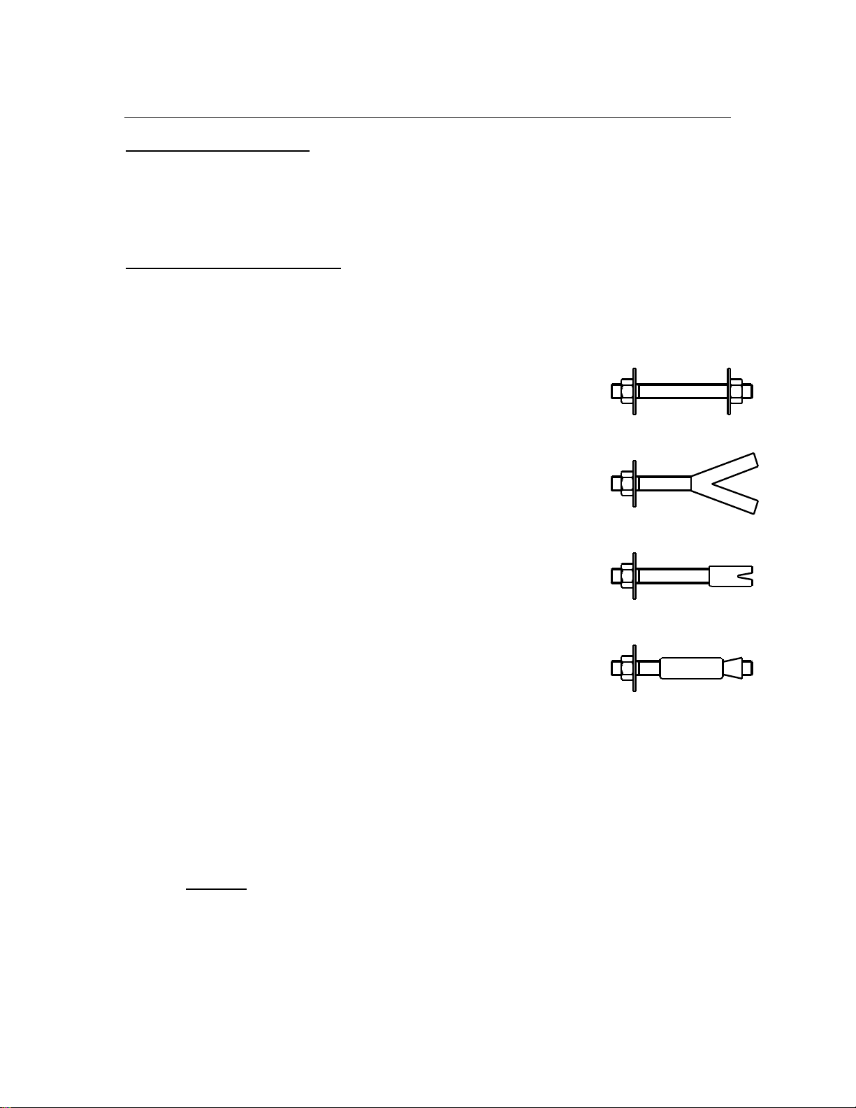
5.2 Anchoring methods
The following anchoring methods can be
alternatively used:
-For installation over ceilings
through bolt (threaded rod)
with washer and nuts M12
-For installation foundation
Stone bolt (length 100 mm/3.9 inch) for cementing in
recessed or morticed holes
(Bolts must not be longer, than the thickness of
the foundation.)
or M12
Heavy-load plugs with threaded rod
in deep bore-holes
or
Safety expanding anchors for inserting
in bore holes
or
adhesive plugs /shear connector. 703871-25-0
Thread for all fixing methods: M 12
Quality: Property class 8.8 -DIN 267
We are not liable for any damage caused by disregarding of our recommendations
and of our information.
Attention
Pay attention to the floor load of the machine floor surface.
The bore holes must be deep enough, to ensure that the plug is
under tension in the conrete.

12
5. Machine fixing
5.3 Cemented-in stone bolts
Work sequences:
Insert stone bolts in the holes of the channel lines of the trough with spring washers and nuts.
Level the machine. If the floor is uneven, level machine with wedges and fill
spaces with epoxy resin.
Fill anchoring holes with quick-taking cement.
After kinding tight nuts evenly.
5.4 Safety expanding anchors
Work sequences:
Install machine at intended location.
Use the holes of the channel lines of the trough, as drilling template. Pilot-drill
with stone drill 14 mm(1/2 inch). Minimum drilling depth 100 mm (3.9 inch).
Remove machine or channel lines of the trough. Bore the 18 mm ( 0.7 inch) holes
with the stone drill 18 mm (0.7 inch). Depth 140 mm (5.5 inch).
Remove nuts and washers of the expanding anchors.
Shorten upper plug brush. Put anchors into the drilled holes.
Put the machine on respectively put the channel lines of the trough on and level.
If the floor is uneven, level with wedges and fill spaces with epoxy resing.
Tight anchor nuts evenly.
5.5 Threaded rods (bored-trough ceiling)
Work sequences:
Install machine at intended location.
Use the holes of the channel lines of the trough as drilling template.
Pilot-drill with stone drill 14 mm (1/2 inch).
Remove machine or channel lines of the trough.
Bore the 16 mm (5/8 inch) holes to a diameter of 20 mm (3/4 inch) with the
stone drill 20 mm (3/4 inch) at normal installation over ceiling (see foundation draft).
Put the machine respectively the channel lines of the trough.
The machine must be completely levelled on the ceiling.
If this is not the case, level with wedges and fill spaces with epoxy resin.

13
5. Machine fixing
5.6 Adhesive plugs /shear connector
Work sequences:
Install machine at the intended location.
Use the holes of the channel lines of the trough as drilling template.
Pilot-drill with stone drill 14 mm (1/2 inch).
Remove machine or channel lines of the trough.
Bore holes: Bore diameter and depth according to the information of the
plug producer and blow dustfree.
Additional working steps can be taken from the manuals of the producers.
Pay attention to the hardening time.
Put machine respectively channel lines of the trough on and level. If the floor is uneven,
level with wedges and fill spaces with epoxy resin.
Tight nuts evenly.

14
6. Installation
6.1 Surrounding conditions
6.1.1 Regulations
Applicable regulations for room ventilation and size, odour
and noise emissions, accident prevention etc. must be met.
The control box contains contacts to control the room air ventilation
(see page 28).
Noise level at a distance of 1 meter (39.3 inch) P 240 /P 300
from the machine and 1.60 m (63 inch) above P 300 USA /P 350 USA
ground (without sound insulation): 64 dB (A)
_________________________________________________________________________
If there is an increase of the airbome sound e.g. by resonance because of space situation
the condition and the distances of the walls and the ceiling etc. it is necessary to take
additional measures of sound insulation.
6.1.2 Temperature
Machine should not be exposed to direct sunlight.
Adequate air supply is to be ensured due to heat exchange
(heat build-up!) Room temperature should not drop below
1 °C (34 °F) owing to the risk of water freezing in the system, and
not exceed 40 °C (104 °F) in continuous operation owing to increased
solvent consumption.
P 240 P 300
P 300 USA P 350 USA
Heat radiation: 9300 kJ 11500 kJ
_________________________________________________________________________
6.1.3 Structural surroundings
Partitions, screens, intermediate ceilings and similar near
the machine are to be fitted in such a way that they do not
hinder operation and are easily and quickly removed for
maintenance and repair.
NOTE!
Do not operate appliances with open flames, e.g. gas-fired
flatwork ironers, tumblers, in the same room, because they
can be damaged by noxious, corrosive gases in the event of
solvent decomposition.
Please ensure that no air from the machine can escape into
a possibly existing heating plant room.
!

15
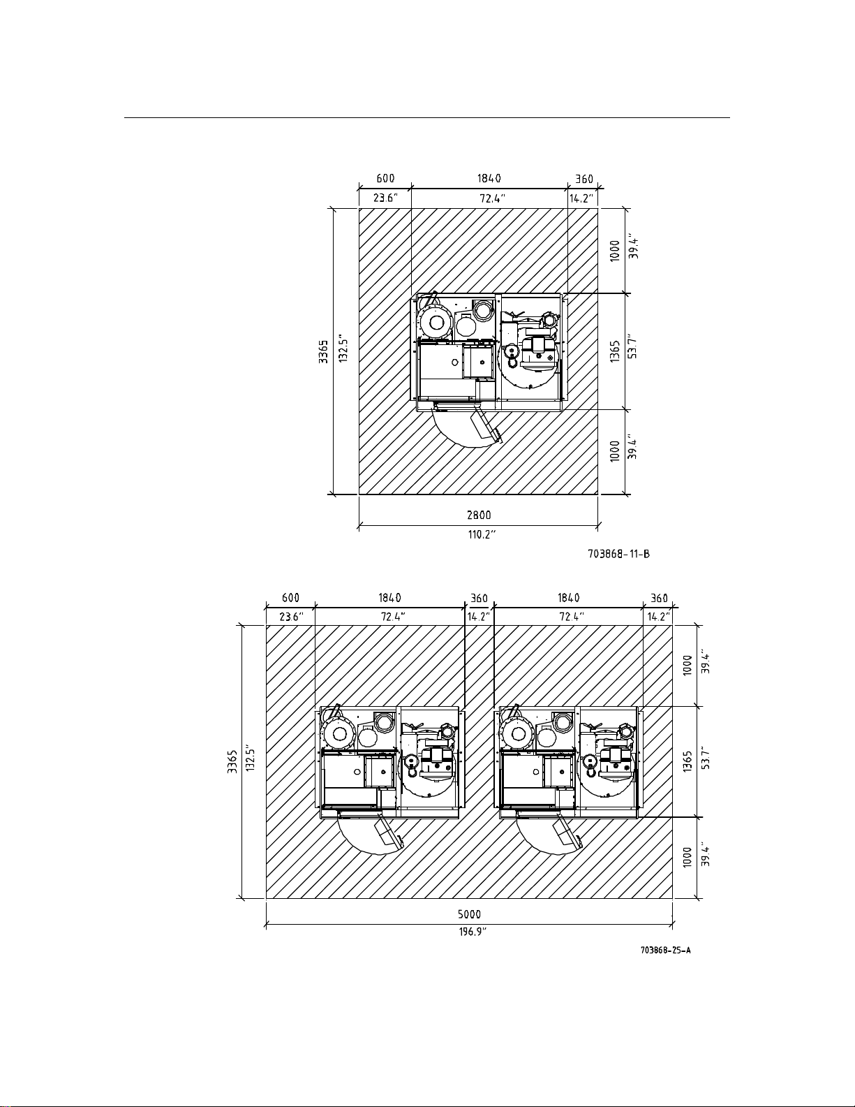
6. Installation
6.2 Place of installation
6.2.1 Required space
Front and rear of the machine should be accessible for
operation, maintenance and repair.
Slimline
Separate installation:
Multiple installation:
16
6. Installation
Crossline
Separate installation:
Multiple installation:

17
6. Installation
6.2.2 Machine dimensions
Slimline Crossline
P 240 /P 300 P 240 /P 300
P 300 USA /P 350 USA P 300 USA /P 350 USA
_______________________________________________________________________________
Width mm 1080 inch 42.5 mm 1840 inch 72.4
Depth mm 2140 inch 84.2 mm 1365 inch 53.7
Height without cool-down flap mm 2105 inch 82.9 mm 2105 inch 82.9
Height with cool-down flap mm 2300 inch 90.6 mm 2300 inch 90.6
6.3 Floor load
The place of installation must conform to the floor load which is composed of:
-static load = machine weight + max. solvent filling and
-dynamic load = centrifugal cage force with normally
distributed, extraction-damp garments.
The force created during extraction must also be taken into account
(floor, supporting walls etc.). Resonances are not permissible.
Please consult building specialists.
6.3.1 Dimensions
Slimline Crossline
P 240 /P 300 P 240 /P 300
P 300 USA /P 350 USA P 300 USA /P 350 USA
________________________________________________________________________
Depth* mm (inch) 1200 (47.2) 1310 (51.6) 1200 (47.2) 1310 (51.6)
Width* mm (inch) 1080 (42.5) 1080 (42.5) 1080 (42.5) 1080 (42.5)
Portion of the floor surface
for the force transmission m² (sq.ft.) 1.3 (14) 1.41 (15.2) 1.3 (14) 1.41 (15.2)
Weight without solvent kg (lb) 980 (38.6) 1080 (42.5) 1080 (42.5) 1100 (43.3)
Weight with solvent
(stat. load) kg (lb) 1300 (51.2) 1470 (57.9) 1400 (55.1) 1490 (58.7)
Centrifugal cage force
(dyn. load) N4800 6000 4800 6000
Floor load (stat. + dyn. load)
-Standard drive N/m² 13600 14500 14300 14600
*Portion of the complete machine dimension, that is decisive
for the floor load and the centrifugal cage force.
Regarding the foundation work please consult building experts.
They will take machine-related as well as local particulars into account
and find the best solution.
Please use a load dispatcher frame if the permissible floor load is inadequate.
This manual suits for next models
2
Table of contents
Popular Washer manuals by other brands


Beko
Beko WMP631S Installation & operating instructions and washing guidance

SCHOLTES
SCHOLTES SMLE 129 Instructions for use

Siemens
Siemens WM07A160ME Series Instruction manual and installation instructions

AEG
AEG LB 1483 user manual

VOV
VOV VWM - 70 instruction manual

King Canada
King Canada KPW-205 Service manual & parts list


