SCHOLTES SMLE 129 User manual

GB
1
Contents
Installation, 2-3-4-5
Unpacking and levelling
Connecting the electricity and water supplies
The first wash cycle
Technical data
Instructions for the fitter
Description of the washing machine, 6-7
Control panel
Display
unning a wash cycle, 8
Wash cycles and functions, 9
Table of wash cycles
Wash functions
Detergents and laundry, 10
Detergent dispenser drawer
Preparing the laundry
Special wash cycles
Load balancing syste
Precautions and tips, 11
General safety
Disposal
Opening the porthole door anually
Care and maintenance, 12
Cutting off the water or electricity supply
Cleaning the washing achine
Cleaning the detergent dispenser drawer
Caring for the door and dru of your appliance
Cleaning the pu p
Checking the water inlet hose
Troubleshooting, 13
Service, 14
SMLE 129
Instructions for use
WASHING MACHINE
English,1
GB ES
Español,29Français,15
F

2
GB
A
Installation
This instruction anual should be kept in a safe
place for future reference. If the washing achine is
sold, transferred or oved, ake sure that the
instruction anual re ains with the achine so that
the new owner is able to fa iliarise hi self/herself
with its operation and features.
Read these instructions carefully: they contain vital
infor ation relating to the safe installation and
operation of the appliance.
Unpacking and levelling
Unpacking
1. Re ove the washing achine fro its packaging.
2. Make sure that the washing achine has not been
da aged during the transportation process. If it has
been da aged, contact the retailer and do not
proceed any further with the installation process.
3. Re ove the 4
protective screws (used
during transportation) and
the rubber washer with
the corresponding
spacer, located on the
rear part of the appliance
(see figure).
4. Close off the holes using the plastic plugs provided.
5. Keep all the parts in a safe place: you will need
the again if the washing achine needs to be
oved to another location.
Packaging aterials should not be used as toys for
children.
Levelling
1. Install the washing achine on a flat sturdy floor,
without resting it up against walls, furniture cabinets
or anything else.
2. If the floor is not
perfectly level, co pen-
sate for any unevenness
by tightening or loosening
the adjustable front feet
(see figure); the angle of
inclination, easured in
relation to the worktop,
ust not exceed 2°.
Levelling the achine correctly will provide it with
stability, help to avoid vibrations and excessive noise
and prevent it fro shifting while it is operating. If it is
placed on carpet or a rug, adjust the feet in such a
way as to allow a sufficient ventilation space
underneath the washing achine.
Connecting the electricity and water
supplies
Connecting the water inlet hose
1. Insert seal A into the
end of the inlet hose and
screw the latter onto a
cold water tap with a 3/4
gas threaded opening
(see figure).
Before perfor ing the
connection, allow the
water to run freely until it
is perfectly clear.
2. Connect the inlet hose
to the washing achine
by screwing it onto the
corresponding water inlet
of the appliance, which is
situated on the top right-
hand side of the rear part
of the appliance (see
figure).
3. Make sure that the hose is not folded over or bent.
The water pressure at the tap ust fall within the
values indicated in the Technical details table (see
next page).
If the inlet hose is not long enough, contact a
specialised shop or an authorised technician.
Never use second-hand hoses.
Use the ones supplied with the achine.

GB
3
Technical data
Model SMLE 129
Dimensions
width 59,5 c
height 81,5 c
depth 54,5 c
Capacity fro 1 to 7 kg
Electrical
connections
please refer to the technical data
plate fixed to the achine
Water connections
axi u pressure 1 MPa (10 bar)
ini u pressure 0.05 MPa (0.5 bar)
dru capacity 52 litres
Spin speed up to 1200 rotations per inute
Energy rated
programmes
according to
regulation
EN 60456
progra e (1st press of the
button); te perature 60°C;
using a load of 7 kg.
This appliance confor s to the
following EC Directives:
- 89/336/EEC dated 03/05/89
(Electro agnetic Co patibility) and
subsequent odifications
- 2002/96/EC
- 2006/95/EC (Low Voltage)
65 - 100 cm
Connecting the drain hose
Connect the drain hose,
without bending it, to a
drainage duct or a wall
drain located at a height
between 65 and 100 c
fro the floor;
alternatively, rest it on
the side of a washbasin
or bathtub, fastening the
duct supplied to the tap
(see figure). The free end
of the hose should not
be underwater.
We advise against the use of hose extensions; if it is
absolutely necessary, the extension ust have the
sa e dia eter as the original hose and ust not
exceed 150 c in length.
Electrical connections
Before plugging the appliance into the electricity
socket, ake sure that:
the socket is earthed and co plies with all
applicable laws;
the socket is able to withstand the axi u power
load of the appliance as indicated in the Technical
data table (see opposite);
the power supply voltage falls within the values
indicated in the Technical data table (see opposite);
the socket is co patible with the plug of the
washing achine. If this is not the case, replace
the socket or the plug.
The washing achine ust not be installed
outdoors, even in covered areas. It is extre ely
dangerous to leave the appliance exposed to rain,
stor s and other weather conditions.
When the washing achine has been installed, the
electricity socket ust be within easy reach.
Do not use extension cords or ultiple sockets.
The cable should not be bent or co pressed.
The power supply cable ust only be replaced by
authorised technicians.
Warning! The co pany shall not be held responsible
in the event that these regulations are not respected.
The first wash cycle
Once the appliance has been installed, and before
you use it for the first ti e, run a wash cycle with
detergent and no laundry, using the wash cycle .

4
GB
Instructions for the fitter
Mounting the wooden panel onto the door and
inserting the machine into cabinets:
In the case where the achine ust be shipped for final
installation after the wooden panel has been ounted, we
suggest leaving it in its original packaging. The packaging
was designed to ake it possible to ount the wooden
panel onto the achine without re oving it co pletely
(see figures below).
The wooden panel that covers the face of the achine
ust not be less than 18 mm in thickness and can be
hinged on either the right or left. For the sake of
practicality when using the achine, we reco end that
the panel be hinged on the sa e side as the door for the
achine itself - the left.
AB
CD
E
Tur seite
Door Mounting Accessories (Fig. 1-2-3-4-5).
Fig. 1
N° 2 Hinges
N° 1 Magnet N° 1 Magnet plate
N° 1 Rubber plug
N° 2 Hinge Supports
N° 4 Spacers
Fig. 2
Fig. 3 Fig. 4
Fig. 5 Fig. 4/B
- No. 6 type A self-threading screws, l =13 .
- No. 2 type B etric, countersunk screws, l =25; for
fastening the agnet plate to the cabinet.
- No. 4 type C etric screws, l =15 ; for ounting the
hinge supports to the cabinet.
- No. 4 type D etric screws, l =7 ; for ounting the
hinges on the supports.
Mounting the Parts onto the Face of the Machine.
- Fit the hinge supports to the appliance front panel,
positioning the hole arked with an arrow in fig. 1 so that it
is on the inner side of the front panel. Fit a spacer (fig. 4/B)
between the surfaces using type C screws.
- Fit the agnet plate at the top of the opposite side,
using type B screws to fix two spacers (fig. 4/B) between
the plate and the surface.

GB
5
Using the Drilling Template.
- To trace the positions of the holes on the left-hand side
of the panel, align the drilling te plate to the top left side
of the panel using the lines traced on the extre ities as a
reference.
- To trace the positions of the holes on the right-hand
side of the panel, align the drilling te plate to the top
right side of the panel.
- Use an appropriately sized router to ill the holes for
the two hinges, the rubber plug and the agnet.
Mounding the Parts onto the Wooden Panel (Door).
- Insert the hinges into the holes (the ovable part of the
hinge ust be positioned facing away fro the panel) and
fasten the with the 4 type A screws.
- Insert the agnet into the top hole on the opposite side
of the hinges and fasten it with the two type B screws.
- Insert the rubber plug into the botto hole.
The panel is now ready to be ounted onto the achine.
Mounting the Panel into the machine.
Insert the nib of the hinge (indicated by the arrow in fig. 2)
into the hole for the hinge and push the panel towards the
front of the achine. Fasten the two hinges with the type
D screws.
Fastening the plinth guide.
If the achine is installed at the end of a set of odular
cabinets, ount either one or both of the guides for the
base olding (as shown in fig. 8). Adjust the for depth
based on the position of the base olding, and, if
necessary, fasten the base to the guides (fig. 9).
This is how to asse ble the plinth guide (fig. 8):
Fasten angle P using screw R, insert plinth guide Q into
the special slot and once it is in the desired position, lock
it in place using angle P and screw R.
Inserting the machine into the Cabinet.
- Push the achine into the opening, aligning it with the
cabinets (fig. 6).
- Regulate the adjustable feet to raise the achine to the
appropriate height.
- To adjust the position of the wooden panel in both the
vertical and horizontal directions, use the C and D
screws, as shown in fig. 7.
Important: lose the lower part of the applian e front by
ensuring that the plinth rests against the floor.
Fig. 8 Fig. 9
Accessories provided for the height adjustment.
The following can be found inside the polystyrene lid (fig. 10):
2 crossbars (G), 1 strip (M)
the following can be found inside
the appliance dru :
4 additional feet (H),
4 screws (I),
4 screws (R),
4 nuts (L),
2 plinth guides (Q)
Adjusting the appliance height.
The height of the appliance can be adjusted (fro 815
to 835 ), by turning the 4 feet.
Should you require the appliance to be placed higher than
the above height, you need to use the following accessories
to raise it to up to 870 :
the two crossbars (G); the 4 feet (H); the 4 screws (I); the 4
nuts (L) then perfor the following operations (fig. 11):
re ove the 4 original feet, place a crossbar G at the front of
the appliance, fastening it in place using screws I (screwing
the in where the original feet were) then insert the new feet H.
Repeat the sa e operation at the back of the appliance.
Now adjust feet H to raise or lower the appliance fro 835
to 870 .
Once you have reached the desired height, lock nuts L onto
crossbar G.
To adjust the appliance to a height between 870 and
900 , you need to ount strip M, adjusting feet H to the
required height.
Insert the strip as follows:
loosen the three screws N situated at the front of the Top
cover of the appliance, insert strip M as shown in fig. 12,
then fasten screws N.
D
C
C
570
min
815
540
595
820 ÷ 900
600 min
Fig. 6 Fig. 7
LI
H
G
M
Fig. 11 Fig. 12
Fig. 10

6
GB
Detergent dispenser drawer: used to dispense
detergents and washing additives (see Detergents
and laundry).
ON/OFF button : press this briefly to switch the
achine on or off. The START/PAUSE indicator light,
which flashes slowly in a green colour shows that the
achine is switched on. To switch off the washing
achine during the wash cycle, press and hold the
button for approxi ately 2 seconds; if the button is
pressed briefly or accidentally the achine will not
switch off. If the achine is switched off during a
wash cycle, this wash cycle will be cancelled.
WASH CYCLE SELECTO buttons: used to set the
desired wash cycle (see "Table of wash y les").
MEMO Y button: press and hold the button to store
a cycle with your own set of preferences in the
e ory of the achine. To recall a previously stored
cycle, press the MEMORY button.
FUNCTION buttons: press the button to select the
desired function. The corresponding indicator light on
the display will switch on.
SPIN button : press to reduce or co pletely
exclude the spin cycle - the value is indicated on the
display.
TEMPE ATU E button : press to decrease the
te perature: the value will be shown on the display.
CONT OL PANEL LOCK button : to activate the
control panel lock, press and hold the button for
approxi ately 2 seconds. When the sy bol is
illu inated, the control panel is locked. This eans it
is possible to prevent wash cycles fro being odified
accidentally, especially where there are children in the
ho e. To deactivate the control panel lock, press
and hold the button for approxi ately 2 seconds.
DELAYED STA T button : press to set a delayed
start ti e for the selected wash cycle. The delay ti e
will be shown on the display.
STA T/PAUSE button with indicator light: when the
green indicator light flashes slowly, press the button to
start a wash cycle. Once the cycle has begun the
indicator light will re ain lit in a fixed anner. To
pause the wash cycle, press the button again; the
indicator light will flash in an orange colour. If the
sy bol is not illu inated, the door ay be
opened. To start the wash cycle fro the point at
which it was interrupted, press the button again.
Description of the washing
machine
Control panel
TEMPE ATU E
Button
WASH
CYCLE
SELECTO
Buttons
Detergent dispenser
drawer
FUNCTION
buttons
ON/OFF
button
SPIN SPEED
Button
STA T/
PAUSE
button with
indicator light
CONT OL
PANEL
LOCK
Button
DISPLAY
DELAYED
STA T
Button
MEMO Y
Button

GB
7
Display
The display is useful when progra ing the achine and provides a great deal of infor ation.
The two upper strings A and B provide details of the wash cycle selected, the wash cycle phase in progress and
all infor ation relating to the progress status of the wash cycle.
String C shows the ti e re aining until the end of the wash cycle in progress and, if a DELAYED START has been
set, the ti e re aining until the start of the selected wash cycle.
String D shows the axi u spin speed value (this depends on the selected wash cycle); if the wash cycle does
not include a spin cycle, the string re ains unused.
String E shows the axi u te perature value which ay be selected (this depends on the wash cycle used); if
the te perature of the wash cycle cannot be odified, the string re ains unused.
Indicator lights F correspond to the functions and light up when the selected function is co patible with the set
wash cycle.
Door locked symbol
If the sy bol is lit, this indicates that the washing achine door is blocked to prevent it fro being opened
accidentally. To prevent any da age fro occurring, wait for the sy bol to switch itself off before opening the
appliance door.
N.B.: if the DELAYED START function has been activated, the door cannot be opened; pauses the achine by
pressing the START/PAUSE button if you wish to open it.
The first ti e the achine is switched on, you will be asked to select the language and the display will
auto atically show the language selection enu.
To select the desired language press the TEMPERATURE and SPIN buttons; to confir the selection press the
CONTROL PANEL LOCK button.
If you wish to select another language, press and hold the CONTROL PANEL LOCK + TEMPERATURE + SPIN
buttons simultaneously for 5 seconds, then repeat the steps listed above.
A
B
C
D
E
F

8
GB
unning a wash cycle
1.SWITCH THE MACHINE ON. Press the
button; the text WELCOME will appear on the
display and the START/PAUSE indicator light will
flash slowly in a green colour.
2. LOAD THE LAUND Y. Open the porthole door.
Load the laundry, aking sure you do not exceed
the axi u load value indicated in the table of
progra es on the following page.
3. MEASU E OUT THE DETE GENT. Pull out the
detergent dispenser drawer and pour the detergent
into the relevant co part ents as described in
"Detergents and laundry".
4. CLOSE THE DOO .
5. SELECT THE WASH CYCLE. Press one of the
WASH CYCLE SELECTOR buttons to select the
required wash cycle; the na e of the wash cycle
will appear on the display. A te perature and spin
speed is set for each wash cycle; these ay be
adjusted. The duration of the cycle will appear on
the display.
6. CUSTOMISE THE WASH CYCLE. Use the
relevant buttons:
Modifying the temperature and/or spin
speed. The achine auto atically selects the
axi u te perature and spin speed set for the
selected wash cycle; these values cannot therefore
be increased. The te perature can be decreased
by pressing the button, until the cold wash
"OFF" setting is reached. The spin speed ay be
progressively reduced by pressing the button,
until it is co pletely excluded (the "OFF" setting). If
these buttons are pressed again, the axi u
values are restored.
Setting a delayed start.
To set a delayed start for the selected progra e,
press the corresponding button repeatedly until the
required delay period has been reached. When this
option is enabled, the sy bol lights up on the
display. To re ove the delayed start function press
the button until the text "OFF" appears on the
display.
Modifying the cycle settings.
Press the button to enable the function; the
indicator light corresponding to the button will
switch on.
Press the button again to disable the function;
the indicator light will switch off.
If the selected function is not co patible with the
progra ed wash cycle, the indicator light will
flash and the function will not be activated.
If the selected function is not co patible with
another function which has been selected
previously, the indicator light corresponding to the
first function selected will flash and only the second
function will be activated; the indicator light
corresponding to the enabled function will re ain lit.
The functions ay affect the reco ended load
value and/or the duration of the cycle.
7. STA T THE P OG AMME. Press the START/
PAUSE button. The corresponding indicator light will
beco e green, re aining lit in a fixed anner, and
the door will be locked (the DOOR LOCKED
sy bol will be on). During the wash cycle, the
na e of the phase in progress will appear on the
display. To change a wash cycle while it is in
progress, pause the washing machine using the
START/PAUSE button (the START/PAUSE indicator
light will flash slowly in an orange colour); then
select the desired cycle and press the START/
PAUSE button again.
To open the door while a cycle is in progress, press
the START/PAUSE button; if the DOOR LOCKED
sy bol is switched off the door ay be
opened. Press the START/PAUSE button again to
restart the wash cycle fro the point at which it
was interrupted.
8. THE END OF THE WASH CYCLE. This will be
indicated by the text "END OF CYCLE" on the
display; when the DOOR LOCKED sy bol
switches off the door ay be opened. Open the
door, unload the laundry and switch off the
achine.
If you wish to cancel a cycle which has already
begun, press and hold the button. The cycle will be
stopped and the achine will switch off.

GB
9
Wash cycles and functions
Wash functions
Stain removal
This function is particularly useful for the re oval of
stubborn stains. Place extra co part ent 4 (supplied)
into co part ent 1. When pouring in the bleach, be
careful not to exceed the "max" level arked on the
central pivot (see figure).
To run the bleach cycle on
its own, pour the bleach
into extra co part ent 4,
set the "Rinse"
progra e and activate
the "Stain re oval"
progra e. To bleach
during a wash cycle, pour
in the detergent and any
fabric softener you wish to
use, set the desired wash
cycle and enable the "Stain re oval" function.
The use of extra compartment 4 excludes the
re-wash function.
It cannot be used with the , , , Drain
progra es.
Prewash
If this function is selected, the pre-wash cycle will run;
this is useful for re oving stubborn stains.
N.B.: put the detergent in the relevant co part ent.
It cannot be used with the , , , , ,
progra es.
For all Test Institutes:
* Test wash cycle in compliance with regulation EN 60456: set wash cycle with a temperature of 60°C.
Table of wash cycles
Extra rinse
By selecting this option, the efficiency of the rinse is
increased and opti al detergent re oval is
guaranteed. It is particularly useful for sensitive skin.
It cannot be used in conjunction with the , ,
Drain progra es.
Easy iron
By selecting this function, the wash and spin cycles
will be odified in order to reduce the for ation of
creases. At the end of the cycle the washing achine
will perfor slow rotations of the dru ; the EASY
IRON and START/PAUSE indicator lights will flash
(orange) and the text "END OF CYCLE" will appear on
the display. To end the cycle, press the START/
PAUSE button or the EASY IRON button.
For the Silk/Curtains cycle, the achine will end the
cycle while the laundry is soaking; the EASY IRON
and START/PAUSE indicator lights will flash (orange)
and the text "STOP WITH WATER" will appear on the
display. To drain the water so that the laundry ay be
re oved, press the START/PAUSE button or the
EASY IRON button.
It ay not be used with the , , , , Drain
progra es.
Mini load
This function is reco ended for when the load of laundry
is equal to half, or less than half, of the axi u
reco ended load (see Table of wash y les).
It cannot be used with the , and Pu p out.
MAX
1
2
4
3
Description of the wash cycle
Max.
temp.
(°C)
Max.
speed
(rpm )
Detergents
Max.
load
(kg)
Max.
load
(kg) Cycle
duration
re-
wash Bleach Wash Fabric
softener Normal Mini
Load
Everyday wash cycles (Daily)
Cotton (*) (1st press of the button): extre ely soiled whites. 90° 1200 lll l 73
Cotton (2nd press of the button): heavily soiled whites and resistant colours. 60° 1200 lll l 73
Cotton
(3rd press of the button): heavily soiled whites and delicate colours. 40° 1200 lll l 73
Synthetics (1st press of the button): heavily soiled resistant colours. 60° 800 lll l 31,5
Synthetics (2nd press of the button): lightly soiled resistant colours. 40° 800 lll l 31,5
Mix 30' (1 st press of the button): to refresh lightly soiled gar ents quickly
(not suitable for wool, silk and clothes which require washing by hand). 30° 800 - - ll 3-
Mix 15' (2nd press of the button ) : to refresh lightly soiled gar ents quickly (not
suitable for wool, silk and clothes which require washing by hand). 30° 800 - - ll 1,5 -
Special cycles / Memory
Baby cycle: heavily soiled delicate colours. 40° 800 -ll l 21
Memory: allows for any wash cycle to be stored.
Silk/Curtains:
for gar ents in silk and viscose, lingerie. 30° 0 - - ll 11
Wool:
for wool, cash ere, etc. 40° 600 -ll l 1,5 1
Partial wash cycles
Fast Spin (1st press of the button) -1200 - - - - 7-
Slow spin (2nd press of the button) -800 - - - - 3-
Rinse cottons (1 st press of the button) -1200 -l-l73
Pu p out (2nd press of the button) -0- - - - 7-
The duration of the wash cycles can be checked
on the display.
Wash cycles
M

10
GB
Detergents and laundry
Detergent dispenser drawer
Good washing results also depend on the correct
dose of detergent: adding too uch detergent will not
necessarily result in a ore efficient wash, and ay in
fact cause build up on the inside of your appliance
and contribute to environ ental pollution.
Do not use hand washing detergents because these
create too uch foa .
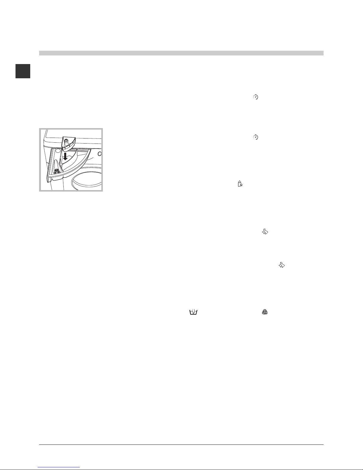
Open the detergent
dispenser drawer and
pour in the detergent or
washing additive, as
follows.
compartment 1: Pre-wash detergent (powder)
Before pouring in the detergent, ake sure that extra
co part ent 4 has been re oved.
compartment 2: Detergent for the wash cycle
(powder or liquid)
Liquid detergent should only be poured in i ediately
prior to the start of the wash cycle.
compartment 3: Additives (fabric softeners, etc.)
The fabric softener should not overflow the grid.
extra compartment 4: Bleach
Preparing the laundry
Divide the laundry according to:
- the type of fabric/the sy bol on the label
- the colours: separate coloured gar ents fro
whites
E pty all gar ent pockets and check the buttons.
Do not exceed the listed values, which refer to the
weight of the laundry when dry:
Durable fabrics: ax. 7 kg
Synthetic fabrics: ax. 3 kg
Delicate fabrics: ax. 2 kg
Wool: ax. 1,5 kg
Silk: ax. 1 kg
How much does your laundry weigh?
1 sheet 400-500 g
1 pillow case 150-200 g
1 tablecloth 400-500 g
1 bathrobe 900-1200 g
1 towel 150-250 g
MAX
1
2
4
3
Special wash cycles
Mix 30: this wash cycle was designed to wash
lightly soiled gar ents quickly: it lasts just 30 inutes
and therefore saves both energy and ti e. By
selecting this wash cycle ( at 30°C), it is possible to
wash different fabrics together (except for wool and
silk ite s), with a axi u load of 3 kg.
Mix 15: this wash cycle was designed to wash
lightly soiled gar ents quickly: it lasts just 15 inutes
and therefore saves both energy and ti e. By
selecting this wash cycle ( at 30°C), it is possible to
wash different fabrics together (except for wool and
silk ite s), with a axi u load of 1.5 kg.
Baby cycle: this wash cycle can be used to re ove
the soiling typically caused by babies, while ensuring
that all detergent is re oved fro nappies in order to
prevent the delicate skin of babies fro suffering
allergies. The cycle has been designed to reduce
the a ount of bacteria by using a greater quantity of
water and opti ising the effect of special disinfecting
additives added to the detergent.
At the end of the wash cycle, the achine will slowly
rotate the dru to prevent the for ation of creases;
to end the cycle press the START/PAUSE button.
Silk: use special wash cycle to wash all silk
gar ents. We reco end the use of special
detergent which has been designed to wash delicate
clothes.
Curtains: fold curtains and place the in a pillow
case or esh bag. Use wash cycle .
Wool: Scholtès is the only washing achine
anufacturer to have been awarded the prestigious
Wool ark Platinu Care endorse ent (M.0508) by
the Wool ark Co pany, which eans that all
woollen gar ents ay be washed in the washing
achine, even those which state hand wash only
on the label. Wash cycle therefore offers
co plete peace of ind when washing woollen
gar ents in the washing achine ( ax. load 1,5 kg)
and guarantees opti al perfor ance.
Load balancing system
Before every spin cycle, to avoid excessive vibrations
and to distribute the load in a unifor anner, the
dru rotates continuously at a speed which is slightly
greater than the washing rotation speed. If, after
several atte pts, the load is not balanced correctly,
the achine spins at a reduced spin speed. If the
load is excessively unbalanced, the washing achine
perfor s the distribution process instead of spinning.
To encourage i proved load distribution and balance,
we reco end s all and large gar ents are ixed
in the load.

GB
11
Precautions and tips
This washing achine was designed and
constructed in accordance with international safety
regulations. The following infor ation is provided for
safety reasons and ust therefore be read carefully.
General safety
This appliance was designed for do estic use only.
The washing achine ust only be used by adults, in
accordance with the instructions provided in this anual.
Do not touch the achine when barefoot or with
wet or da p hands or feet.
Do not pull on the power supply cable when
unplugging the appliance fro the electricity
socket. Hold the plug and pull.
Do not open the detergent dispenser drawer while
the achine is in operation.
Do not touch the drained water as it ay reach
extre ely high te peratures.
Never force the porthole door. This could da age
the safety lock echanis designed to prevent
accidental opening.
If the appliance breaks down, do not under any
circu stances access the internal echanis s in
an atte pt to repair it yourself.
Always keep children well away fro the appliance
while it is operating.
The door can beco e quite hot during the wash cycle.
If the appliance has to be oved, work in a group
of two or three people and handle it with the ut ost
care. Never try to do this alone, because the
appliance is very heavy.
Before loading laundry into the washing achine,
ake sure the dru is e pty.
Disposal
Disposing of the packaging aterials: observe local
regulations so that the packaging ay be re-used.
The European Directive 2002/96/EC on Waste
Electrical and Electronic Equip ent, requires that
old household electrical appliances ust not be
disposed of in the nor al unsorted unicipal waste
strea . Old appliances ust be collected
separately in order to opti ise the recovery and
recycling of the aterials they contain and reduce
the i pact on hu an health and the environ ent.
The crossed out "wheeled bin" sy bol on the
product re inds you of your obligation, that when
you dispose of the appliance it ust be separately
collected.
Consu ers should contact their local authority or
retailer for infor ation concerning the correct
disposal of their old appliance.
Opening the porthole door manually
In the event that it is not possible to open the
porthole door due to a powercut, and if you wish to
re ove the laundry, proceed as follows:
1. re ove the plug fro the electrical socket.
2. ake sure the water level inside the achine is
lower than the door opening; if it is not, re ove
excess water using the drain hose, collecting it in a
bucket.
3. pull outwards using the tab as indicated in the
figure, until the plastic tie-rod is freed fro its stop
position; pull downwards and open the door at the
sa e ti e.

12
GB
Care and maintenance
Cutting off the water and electricity
supplies
Turn off the water tap after every wash cycle. This
will li it wear on the hydraulic syste inside the
washing achine and help to prevent leaks.
Unplug the washing achine when cleaning it and
during all aintenance work.
Cleaning the washing machine
The outer parts and rubber co ponents of the
appliance can be cleaned using a soft cloth soaked
in lukewar soapy water. Do not use solvents or
abrasives.
Cleaning the detergent dispenser
drawer
Re ove the dispenser
by raising it and pulling it
out (see figure).
Wash it under running
water; this operation
should be repeated
frequently.
Caring for the door and drum of your
appliance
Always leave the porthole door ajar in order to
prevent unpleasant odours fro for ing.
Cleaning the pump
The washing achine is fitted with a self-cleaning
pu p which does not require any aintenance.
So eti es, s all ite s (such as coins or buttons)
ay fall into the pre-cha ber which protects the
pu p, situated in its botto part.
Make sure the wash cycle has finished and
unplug the appliance.
To access the pre-cha ber:
1. unscrew the lid by
rotating it anti-clockwise
(see figure): a little water
ay trickle out. This is
perfectly nor al;
2. clean the inside thoroughly;
3. screw the lid back on;
Checking the water inlet hose
Check the inlet hose at least once a year. If there are
any cracks, it should be replaced i ediately: during
the wash cycles, water pressure is very strong and a
cracked hose could easily split open.
Never use second-hand hoses.
1
2

GB
13
Troubleshooting
Your washing achine could fail to work. Before contacting the Technical Assistance Centre (see Assistan e),
ake sure that the proble cannot be not solved easily using the following list.
Problem:
The washing machine does not
switch on.
The wash cycle does not start.
The washing machine does not
take in water (the text "NO
WATE , CHECK SUPPLY"
appears on the display).
The washing machine
continuously takes in and
drains water.
The washing machine does not
drain or spin.
The washing machine vibrates a
lot during the spin cycle.
The washing machine leaks.
The machine is locked and the
display flashes, indicating an
error code (e.g. F-01, F-..).
There is too much foam.
Possible causes / Solutions:
The appliance is not plugged into the socket fully, or is not aking contact.
There is no power in the house.
The washing achine door is not closed properly.
The ON/OFF button has not been pressed.
The START/PAUSE button has not been pressed.
The water tap has not been opened.
A delayed start has been set (see Running a wash y le).
The water inlet hose is not connected to the tap.
The hose is bent.
The water tap has not been opened.
There is no water supply in the house.
The pressure is too low.
The START/PAUSE button has not been pressed.
The drain hose is not fitted at a height between 65 and 100 c fro
the floor (see Installation).
The free end of the hose is under water (see Installation).
The wall drainage syste is not fitted with a breather pipe.
If the proble persists even after these checks, turn off the water tap,
switch the appliance off and contact the Assistance Service. If the
dwelling is on one of the upper floors of a building, there ay be proble s
relating to water drainage, causing the washing achine to fill with water
and drain continuously. Special anti-draining valves are available in shops
and help to avoid this inconvenience.
The wash cycle does not include draining: so e wash cycles require the
drain phase to be started anually (see Wash y les and fun tions).
The EASY IRON function has been activated: To co plete the wash
cycle, press the START/PAUSE button (see Wash y les and fun tions).
The drain hose is bent (see Installation).
The drainage duct is clogged.
The dru was not unlocked correctly during installation (see Installation).
The washing achine is not level (see Installation).
The washing achine is trapped between cabinets and walls (see Installation).
The water inlet hose is not screwed on properly (see Installation).
The detergent dispenser drawer is blocked (for cleaning instructions, see Care
and maintenan e).
The drain hose is not fixed properly (see Installation).
Switch off the achine and unplug it, wait for approxi ately 1 inute
and then switch it back on again.
If the proble persists, contact the Technical Assistance Service.
The detergent is not suitable for achine washing (it should display the
text for washing achines or hand and achine wash, or the like).
Too uch detergent was used.

14
GB
Service
Before calling for Assistance:
Check whether you can solve the proble alone (see Troubleshooting);
Restart the progra e to check whether the proble has been solved;
If this is not the case, contact an authorised Technical Assistance Centre using the telephone nu ber
provided on the guarantee certificate.
Always request the assistance of authorised technicians.
Have the following information to hand:
the type of proble ;
the appliance odel (Mod.);
the serial nu ber (S/N).
This infor ation can be found on the data plate applied to the rear of the washing achine, and can also
be found on the front of the appliance by opening the door.

FR
15
Français
Sommaire
Installation, 16-17-18-19
Déballage et mise à niveau
Raccordements eau et électricité
Premier cycle de lavage
Caractéristiques techniques
Instructions pour l'installateur
Description du lave-linge, 0- 1
Bandeau de commandes
Écran
Comment faire un cycle de lavage,
Programmes et fonctions, 3
ableau des programmes
Fonctions de lavage
Produits lessiviels et linge, 4
iroir à produits lessiviels
riage du linge
Programmes spéciaux
Système déquilibrage de la charge
Précautions et conseils, 5
Sécurité générale
Mise au rebut
Ouverture manuelle de la porte hublot
Entretien et soin, 6
Coupure de larrivée deau et du courant
Nettoyage du lave-linge
Nettoyage du tiroir à produits lessiviels.
Entretien du hublot et du tambour
Nettoyage de la pompe
Contrôle du tuyau darrivée de leau
Anomalies et remèdes, 7
Assistance, 8
FR
SMLE 1 9
Mode demploi
LAVE-LINGE

16
FR
A
Installation
Conserver ce mode demploi pour pouvoir le
consulter à tout moment. En cas de vente, de
cession ou de déménagement, veiller à ce quil suive
toujours le lave-linge pour que son nouveau
propriétaire soit informé sur son mode de
fonctionnement et puisse profiter des conseils
correspondants.
Lire attentivement les instructions: elles fournissent
des conseils importants sur linstallation, lutilisation et
la sécurité de lappareil.
Déballage et mise à niveau
Déballage
1. Déballer le lave-linge.
2. Contrôler que le lave-linge na pas été endommagé
pendant le transport. Sil est abîmé, ne pas le
raccorder et contacter le vendeur.
3. Enlever les 4 vis de
protection servant au
transport, le caoutchouc
et la cale, placés dans la
partie arrière (voir figure).
4. Boucher les trous à laide des bouchons plastique
fournis.
5. Conserver toutes ces pièces: il faudra les remonter
en cas de transport du lave-linge.
Les pièces demballage ne sont pas des jouets pour
enfants.
Mise à niveau
1. Installer le lave-linge sur un sol plat et rigide, sans
lappuyer contre des murs, des meubles ou autre.
2. Si le sol nest pas
parfaitement horizontal,
visser ou dévisser les
pieds de réglage avant
(voir figure) pour niveler
lappareil; son angle
dinclinaison, mesuré sur
le plan de travail, ne doit
pas dépasser 2°.
Une bonne mise à niveau garantit la stabilité de
lappareil et évite quil y ait des vibrations, du bruit et
des déplacements en cours de fonctionnement. Si la
machine est posée sur de la moquette ou un tapis,
régler les pieds de manière à ce quil y ait
suffisamment despace pour assurer une bonne
ventilation.
Raccordements eau et électricité
Raccordement du tuyau darrivée de leau
1. Monter le joint A sur
lextrémité du tuyau
dalimentation et le visser
à un robinet deau froide
à embout fileté 3/4 gaz
(voir figure).
Faire couler leau jusquà
ce quelle soit limpide et
sans impuretés avant de
raccorder.
2. Raccorder le tuyau
darrivée de leau au
lave-linge en le vissant à
la prise deau prévue,
dans la partie arrière en
haut à droite (voir figure).
3. Attention à ce que le tuyau ne soit pas plié ou
écrasé.
La pression de leau doit être comprise entre les
valeurs indiquées dans le tableau des Caractéristiques
techniques (voir page ci-contre).
Si la longueur du tuyau dalimentation ne suffit pas,
sadresser à un magasin spécialisé ou à un technicien
agréé.
Nutiliser que des tuyaux neufs.
Utiliser ceux qui sont fournis avec lappareil.

FR
17
65 - 100 cm
Raccordement du tuyau de vidange
Raccorder le tuyau
dévacuation, sans le
plier, à un conduit
dévacuation ou à une
évacuation murale placés
à une distance du sol
comprise entre 65 et 100
cm;
ou bien laccrocher à un
évier ou à une baignoire,
dans ce cas, fixer le
support en plastique
fourni avec lappareil au
robinet (voir figure).
Lextrémité libre du tuyau
dévacuation ne doit pas
être plongée dans leau.
Lutilisation dun tuyau de rallonge est absolument
déconseillée mais si on ne peut faire autrement, il faut
absolument quil ait le même diamètre que le tuyau
original et sa longueur ne doit pas dépasser 150 cm.
Branchement électrique
Avant de brancher la fiche dans la prise de courant,
sassurer que:
la prise est bien reliée à la terre et est conforme aux
réglementations en vigueur;
la prise est bien apte à supporter la puissance
maximale de lappareil indiquée dans le tableau des
Caractéristiques techniques (voir ci-contre);
la tension dalimentation est bien comprise entre les
valeurs figurant dans le tableau des Caractéristiques
techniques (voir ci-contre);
la prise est bien compatible avec la fiche du lave-
linge. Autrement, remplacer la prise ou la fiche.
Le lave-linge ne doit pas être installé dehors, même
à labri, car il est très dangereux de le laisser exposé
à la pluie et aux orages.
Après installation du lave-linge, la prise de courant
doit être facilement accessible.
Nutiliser ni rallonges ni prises multiples.
Le câble ne doit être ni plié ni trop écrasé.
Le câble dalimentation ne doit être remplacé que
par des techniciens agréés.
Attention! Nous déclinons toute responsabilité en cas
de non-respect des normes énumérées ci-dessus.
Premier cycle de lavage
Avant la première mise en service de lappareil,
effectuer un cycle de lavage avec un produit lessiviel
mais sans linge et sélectionner le programme .
Caractéristiques techniques
Modèle SMLE 129
Dimensions
largeur 59,5 cm
hauteur 81,5 cm
profondeur 54,5 cm
Capacité de 1 à 7 kg
Raccordements
électriques
Voir la plaque signalétique appliquée
sur la machine
Raccordements
hydrauliques
pression maximale 1 MPa (10 bar)
pression minimale 0,05 MPa (0,5 bar)
capacité du tambour 52 litres
Vitesse
d'essorage jusqu'à 1200 tours minute
Programmes de
contrôle selon la
norme EN 60456
programme (1° pression de la
touche); température 60°C;
effectué avec une charge de 7 kg.
Cet appareil est conforme aux
Directives Communautaires suivantes:
- 89/336/CEE du 03/05/89
(Compatibilité électromagnétique) et
modifications suivantes
- 2002/96/CE
- 2006/95/CE (Basse ension)

18
FR
Instructions pour l'installateur
Application du panneau d'habillage en bois sur
la porte et montage du machine à laver à
l'intérieur des éléments:
Au cas où, après le montage du panneau en bois, il faudrait
expédier la machine pour son installation finale, nous vous
conseillons de la laisser dans son emballage d'origine.
L'emballage a été justement réalisé de manière à permettre
le montage du panneau en bois sur la machine sans
déballer complètement le produit (voir figures ci-dessous).
Le panneau en bois couvrant la façade ne doit pas avoir
plus de 18 mm d'épaisseur, il peut être articulé tant à
droite qu'à gauche. Pour plus de facilité d'emploi, nous
conseillons d'adopter le même sens d'ouverture que pour
le hublot dont les charnières sont montées sur le côté
gauche.
AB
CD
E
Tur seite
Accessoires montage porte (Fig.1-2-3-4-5).
Fig. 1
N°2 Charnière
N°1 Aimant N°1 Butoir aimant
N°1 Cheville en
caoutchouc
N°2 Supports charnière
N°4 Cales
Fig. 2
Fig. 3 Fig. 4
Fig. 5 Fig. 4/B
- 6 vis autotaraudeuses l = 13 mm "type A".
- 2 vis métriques à tête évasée l = 25 mm "type B"; pour
fixation du butoir aimant au meuble.
- 4 vis métriques l = 15 mm "type C"; pour montage des
supports charnière au meuble.
- 4 vis métriques l = 7 mm "type D"; pour montage des
charnières aux supports.
Montage des pièces sur la façade de la machine.
- Montez les supports de la charnière sur la façade, en
positionnant le trou indiqué par une flèche dans la fig. 1
vers lintérieur de la façade et interposez une cale (fig. 4/B).
Utilisez les vis type C.
- Montez le butoir aimant du côté opposé en haut et
interposez deux cales (fig. 4/B). Utilisez les deux vis type B.

FR
19
Utilisation du gabarit de forage.
- Pour marquer l'emplacement des trous sur le côté du
panneau, alignez le gabarit de perçage avec le côté
supérieur gauche du panneau en vous servant des lignes
tracées aux extrémités.
- Pour marquer l'emplacement des trous sur le côté droit
du panneau, alignez le gabarit de perçage avec le côté
supérieur droit du panneau.
- Réalisez à l'aide d'une fraise appropriée les quatre
emplace-ments où devront trouver place les deux
charnières, la cheville en caoutchouc et l'aimant.
Montage des pièces sur le panneau en bois (Porte).
- Montez les charnières aux emplacements prévus (la
partie mobile de la charnière doit se trouver vers l'extérieur
du panneau) et fixez-les à l'aide de 4 vis type A.
- Montez l'aimant à son emplacement en haut, à l'opposé
des charnières et fixez-le au moyen de deux vis type B.
- Montez la cheville en caoutchouc à sa place en bas.
Le panneau est à présent prêt, vous pouvez le monter sur
la machine.
Montage du panneau sur la machine.
Introduisez l'ergot de la charnière indiqué par la flèche fig. 2
dans le logement du support charnière, poussez le panneau
vers la façade de la machine et fixez les deux charnières à
l'aide des deux vis type D.
Fixation du support de la base.
Si la machine est installée à une extrémité de la cuisine
intégrée, montez une ou les deux glissières du socle
comme illustré fig. 8 en réglant leur profondeur en
fonction de la position du socle et, au besoin, fixez-le à
ces dernières fig. 9. Pour monter le support de la base,
procédez comme suit (fig. 8): Fixez l'équerre P à l'aide de
la vis R, insérez le support de la base Q dans la fente
prévue et après l'avoir dûment positionné bloquez-le à
l'aide de l'équerre d'assemblage P et de la vis R.
Montage de la machine à l'intérieur des éléments.
- Poussez la machine à travers l'ouverture en l'alignant
aux autres meubles (fig. ).
- Servez-vous des pieds de réglage pour amener la
machine à la hauteur désirée.
- Pour régler la position du panneau en bois à la verticale et à
l'horizontale, servez-vous des vis C et D comme illustré fig. 7.
Important: fermez la partie inférieure de la façade, la base
touchant au sol.
Fig. 8 Fig. 9
Accessoires fournis pour le réglage de la hauteur.
Vous trouverez à l'intérieur du couvercle en polystyrène (fig. 10):
2 traverses (G); 1 listel (M);
et à l'intérieur du tambour :
4 pieds supplémentaires (H),
4 vis (I),
4 vis (R),
4 écrous (L),
2 supports pour la base (Q)
Réglage de la machine en hauteur.
La machine peut être réglée en hauteur (de 815 mm à 835
mm) à l'aide de ses 4 pieds.
Si vous souhaitez l'amener à une hauteur supérieure à celle
qui est indiquée plus haut, c'est à dire jusqu'à 870 mm,
utilisez les accessoires suivants :
les 2 traverses (G); les 4 pieds (H); les 4 vis (I); les 4 écrous
(L) puis procédez comme suit (fig. 11):
démontez les 4 pieds originaux, positionnez une traverse G
dans la partie avant de la machine, fixez-la à l'aide des vis I
(en les vissant dans les trous où étaient fixés les pieds
originaux) puis montez les nouveaux pieds H.
Procédez de même dans la partie arrière de la machine.
Vous pouvez alors régler les pieds H pour élever ou abaisser
la machine de 835 mm à 870 mm.
Après avoir atteint la hauteur désirée, bloquez les écrous L à
la traverse G.
Pour régler la machine à une hauteur comprise entre 870
mm et 900 mm, montez le listel M et réglez les pieds H
jusqu'à la hauteur souhaitée.
Pour monter le listel, procédez comme suit:
desserrez les trois vis N situées dans la partie avant du couvercle,
montez le listel M comme illustré fig. 12 et serrez les vis N.
D
C
C
570
min
815
540
595
820 ÷ 900
600 min
Fig. 6 Fig. 7
LI
H
G
M
Fig. 11 Fig. 12
Fig. 10

0
FR
Tiroir à produits lessiviels: pour charger les
produits lessiviels et les additifs (voir Produits lessiviels
et linge).
asto MARCHE/ARRÊT : appuyer brièvement sur
la touche pour allumer ou éteindre l'appareil. Le
voyant vert MISE EN MARCHE/PAUSE clignotant
lentement indique que la machine est allumée. Pour
éteindre le lave-linge en cours de lavage, appuyer sur
la touche pendant au moins 2 secondes de suite ;
une pression brève ou accidentelle n'entraîne pas
l'arrêt de l'appareil. L'arrêt de l'appareil pendant un
lavage annule le lavage en cours.
ouches SÉLECTEUR PROGRAMMES: pour
sélectionner le programme désiré (voir "Tableau des
programmes").
ouche MEMO: maintenir la touche enfoncée pour
mémoriser un cycle et les personnalisations préférées.
Pour retourner à un cycle précédemment mémorisé,
appuyer sur la touche MEMO.
ouches FONCTION: appuyer sur la touche pour
sélectionner la fonction désirée. Le voyant
correspondant s'affiche à l'écran.
ouche ESSORAGE : appuyer sur cette touche
pour diminuer la vitesse de l'essorage ou pour le
supprimer complètement - la valeur correspondante
s'affiche à l'écran.
ouche TEMPERATURE : appuyer pour diminuer
la température : la valeur correspondante est affichée
à l'écran.
ouche VERROUILLAGE TOUCHES : pour
activer le verrouillage des commandes, garder la
touche enfoncée pendant environ 2 secondes. Le
symbole allumé indique que le bandeau de
commandes est verrouillé. Ceci permet d'éviter toute
modification involontaire des programmes, surtout s'il
y a des enfants à la maison. Pour désactiver le
verrouillage des commandes, garder la touche
enfoncée pendant environ 2 secondes.
ouche DÉPART DIFFÉRÉ : appuyer sur cette
touche pour sélectionner un départ différé pour le
programme choisi. Le retard est affiché à l'écran.
ouche avec voyant MISE EN MARCHE/PAUSE:
quand le voyant vert clignote lentement, appuyer sur
la touche pour démarrer un lavage. Une fois le cycle
lancé, le voyant passe à l'allumage fixe. Pour activer
une pause de lavage, appuyer à nouveau sur la
touche ; le voyant passe à l'orange et se met à
clignoter. Si le symbole n'est pas allumé, il est
possible d'ouvrir le hublot. Pour faire redémarrer le
lavage exactement à l'endroit de l'arrêt, appuyer une
nouvelle fois sur la touche.
Description du lave-linge
Bandeau de commandes
ouche avec
voyant
MISE
EN MARCHE/
PAUSE
ouche
TEMPÉRATURE
ouches
SÉLECTEUR
PROGRAMMES
Tiroir à produits lessiviels
ouches
FONCTION
ouche
MARCHE/ARRÊT
ouche
ESSORAGE
ouche
VERROUILLAGE
TOUCHES
Écran
ouche
DÉPART
DIFFÉRÉ
ouche
MEMO
Other manuals for SMLE 129
2
Table of contents
Languages:
Other SCHOLTES Washer manuals