BOWMAN EC Series Owner's manual

HYDRAULIC OIL COOLER
Installation, Operation
& Maintenance Guide
REG NO FM 38224
BS EN ISO 9001-2008

2
Rev D
Foreword
Dear Customer,
BOWMAN®has been manufacturing high quality hydraulic oil coolers for over 60 years.
Your BOWMAN®Stockist/dealer will be happy to provide you with advice and practical assistance.
Please read these instructions fully and carefully.
Keep the Installation, Operation & Maintenance Guide for future reference to ensure the long lasting
performance from your new Hydraulic Oil Cooler.
Copies of the Hydraulic Oil Cooler brochure are available in other languages from:
French
German http://www.ejbowman.co.uk/downloads.htm
Italian
Spanish
All rights reserved
E.J. Bowman (Birmingham) Ltd, reservethe right to changespecification and technical alteration without prior notice.
No part of thisguide may bereproduced ortransmittedin any form or by any means including reproduction orrecording without written
permissionfrom E.J. Bowman(Birmingham) Ltd.

3
Rev D
H Y D R A U L I C O I L C O O L E R
Installation, Operation & Maintenance Guide
Contents
Foreword 2
1 . S A F E T Y
1.1 Hazards when handling the heat exchanger 4
1.2 Approved use 4
1.3 Potential hazards 4
2 . I N S T A L L A T I O N
2.1 Transport / storage 5
2.2 Fitting 5
2.3 Connecting the heat exchanger 6
2.4 Notes on zinc anodes 7
3 . O P E R A T I O N 8
4 . C O M M I S S I O N I N G 8
5 . M A I N T E N A N C E / R E P A IR
5.1 Winter shut-down in areas exposed to frost 9
5.2 General maintenance 9
5.3 Cleaning 9
5.4 End cover bolt tightening sequence 10
6. PO T E N T I A L S E R V I C E I S S U E S
6.1 Tube failures 10
6.2 Fault finding 11
7. WA R R A N T Y 11
8 . S P A R E P A R T S 11
9 . C E M A R K I N G 12
E.J.Bowman (Birmingham) Ltd
Chester Street • Birmingham • B6 4AP • United Kingdom
Tel: +44 (0)121 359 5401 • Fax: +44 (0)121 359 7495
Email: info@ejbowman.co.uk • website: www.ejbowman.co.uk

Rev D
4
1 Safety
1.1 Hazards when handling the heat exchanger
BOWMAN®Hydraulic Oil Coolers are constructed to current practice and recognised safety standards.
Hazards may still arise from operation, such as:
- Injury of the operator or
- Third parties or
- Damage to the heat exchanger or
- Damage to property and equipment
Any person involved with the installation, commissioning, operation, maintenance or repair of the heat
exchanger must be:
-Physically and mentally capable of performing such work
-Appropriately qualified.
-Comply completely with the installation instructions
The heat exchanger must only be used for its intended purpose.
In the event of breakdowns which may compromise safety a suitably qualified person must always be
contacted.
1.2 Approved use
BOWMAN®Hydraulic Oil Coolers are only approved for cooling hydraulic oil. Any other use unless
specified by BOWMAN®is not approved. BOWMAN®declines all liability for damage associated or
arising from such use.
The maximum permissible operating pressure must not exceed:
Oil (primary side) : 20 bar max.
Water (secondary side) : 16 bar max.
Applies to EC-RK three pass threaded connections only –for other versions please contact
BOWMAN®for guidance.
The maximum permissible operating temperature must not exceed:
Oil (primary side) : 120 Deg.C
Cooling Water (secondary side) : 110 Deg.C
Variants with higher temperature and pressure ratings are available. Please contact the Sales for further
details.
Rev D
5
1.3 Potential hazards
Ensure the maximum permissible operating pressure on the primary or secondary side of the heat
exchanger is not exceeded. The heat exchanger or surrounding equipment may be damaged.
NB: before the oil cooler is disconnected it must be allowed to cool sufficiently and be depressurized to
prevent injury. The supply and returns to the heat exchanger should be isolated to minimise fluid loss.
2 Installation
2.1 Transport / storage
The heat exchanger must be fully drained down prior to transportation. Once drained and fully dry, the
heat exchanger must only be stored indoors within a non aggressive atmosphere. The connections
should be capped to avoid ingress of dirt and contaminants.
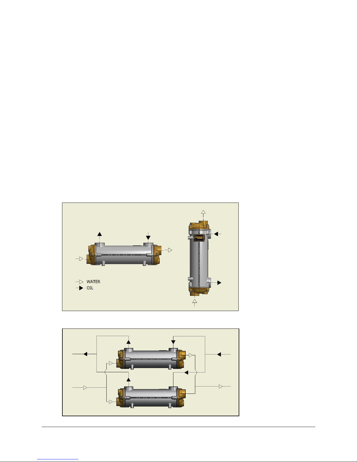
2.2 Fitting
Before fitting, the heat exchanger should be checked for visible signs of damage. The oil cooler can be
positioned horizontally or vertically and should be connected in counterflow so that the fluids flow in
opposite directions, as shown below:
Multiple units can be connected in parallel:
Rev D
6
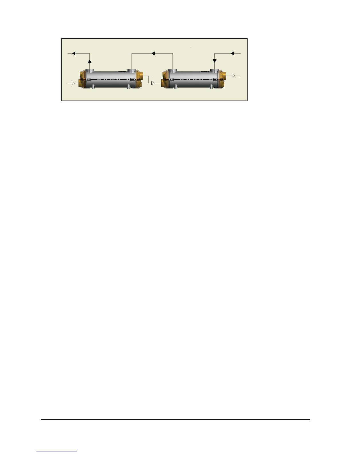
Or in series:
A filter with a maximum permeability of 2.0mm should be used prior to the inlet of each circuit of the
oil cooler.
Nothing should be welded to any part of the oil cooler. Each unit has threaded holes on its underside to
facilitate mounting.
2.3 Connecting the heat exchanger
Shut off all drainage valves in the flow and return pipes of the primary and secondary circuits.
When fitting the heat exchanger into the pipe work care must be taken to ensure that no debris has been
introduced into the primary or secondary circuit of the heat exchanger.
Unsupported lengths of pipework should be avoided so as not to subject the heat exchanger to
excessive loads.
Water side pipework diameter should not reduce to less than the connection size within a distance of
1m from the oil cooler.
Measures should be taken to isolate the oil cooler from excessive vibration.
Taper fittings are not recommended as these can split the shell and end cover castings if over tightened.
The correct length of fitting should be used as too long a fitting will damage the tubestack.
Pipework materials must be compatible with the oil cooler materials. Stainless steel sea water pipes and
fittings should not be used adjacent to the heat exchanger.
If the sea water supply is taken from the ships main, ensure that the recommended flow rate
cannot be exceeded. This will normally mean that an orifice plate must be fitted in the pipe work at
least 1m before the cooler with the orifice size calculated to ensure that the maximum sea water
flow rate cannot be exceeded. If these precautions are not taken, it is possible that the sea water
flow rate through the cooler may be several times the recommended maximum which will lead to
rapid failure.
For our oil coolers, the maximum permitted sea water flow rates are as follows:
EC range 50 l/min. GK range 300 l/min.
FC range 80 l/min. JK range 400 l/min.
FG range 110 l/min. PK range 650 l/min.
GL range 200 l/min. RK range 900 l/min.

Rev D
7
No oil cooler manufacturer can guarantee that his products will have an indefinite life and for this
reason, we suggest that the cooling system is designed to minimise any damage caused by a leaking
oil cooler. This can be achieved as follows:
1. The oil pressure should be higher than the sea water pressure, so that in the event of a leak
occurring, the oil will not be contaminated.
2. When the hydraulic system is not being used, the coolers should be isolated from sea water
pressure.
3. The sea water outlet pipe from the cooler should have a free run to waste.
4. Stainless steel sea water pipes and fittings should not be used adjacent to the oil cooler.
Three Pass Bowman
Heat Exchangers
Oil cooler
Max. sea
water flow
l/min
Orifice diameter in mm for max. sea water flow
series
1 bar
2 bar
3 bar
4 bar
5 bar
6 bar
7 bar
8 bar
9 bar
10
bar
EC
50
11
9.5
8.5
8
7.5
7.2
6.8
6.7
6.5
6.3
FC
80
14
12
11
10.0
9.5
9
8.7
8.4
8.2
8
FG
110
17
14
13
12
11
10
10
9.8
9.6
9.3
GL
200
23
19
17
16
15
14
14
13
13
13
GK
300
28
23
21
19
18
17
17
6
16
15
JK
400
32
27
24
22
21
20
20
19
18
18
PK
650
41
34
31
28
27
26
25
24
23
23
2.4 Notes on zinc anodes
The use of zinc anodes in heat exchangers has been employed for some years, generally by
manufacturers using admiralty brass tube or its variants. The purpose of the zinc anode, or zinc pencil
as it is sometimes called, is to prevent dezincification of the brass alloy tubes. As such zinc anode acts
sacrificially in favour of the tube.
There are a number of American and European manufacturers that use these anodes in their products.
Bowman, do not fit zinc anodes as the tubes used in the construction of our coolers are of copper nickel
alloy and as such do not require a zinc anode. It is possible that if this anode is fitted it can actually
destroy the copper oxide film built up by the tube as a natural defence which can allow the tube material
to be attacked.
It is usual with the copper nickel alloys to use an iron anode which allows an iron oxide film to build up
inside the tube which breaks down as a sacrificial element reducing the possibility of corrosion to the
heat exchanger. In Bowman designs it is not practical to fit iron anodes as their size has to be very
generous. Therefore as an alternative a piece of black iron pipework can be placed before the heat
exchanger which in itself acts as sacrificial element protecting the cooler. The Royal Navy has often
used this technique and when the black iron pipework corrodes, it is simply replace with a fresh piece.
We do know that some manufacturers of heat exchangers, mostly those providing copies of the better
known products, often fit zinc anodes incorrectly with copper nickel alloys in error.

Rev D
8
3 Operation
The oil cooler should be pressurized on the oil (shell) side such that it is at a higher pressure than the
water (tube) side. This will ensure that if a leak occurs it will be detected by a reduction in the oil level
and the oil will not be contaminated. A differential pressure of 2 bar would be sufficient.
It is essential that the following instructions are followed to prevent corrosion/erosion of the heat
exchanger:
a) Always maintain the water pH to within correct levels. The ideal water pH should be kept within 7.4
to 7.6. On no account should it fall below 7.2 or above 7.8.
b) Maximum fluid velocity through the oil cooler of 2m/s for sea water (ideal sea water flow rates are
detailed on page 7) or 3m/s for fresh water must not be exceeded. If in doubt contact
BOWMAN®for guidance. For shipboard installations an information sheet with orifice plate sizes
is available.
c) Minimum water velocity of 1m/s should be used.
d) Ensure compliance with water quality and maximum permissible pressure requirements.
e) Air must be adequately vented from both circuits.
f) Stagnant water should not be allowed to accumulate in the oil cooler. If it is not in use for any
period of time the water should be drained off.
4 Commissioning
Commissioning of the heat exchanger should not be undertaken until such time that this document has
been fully read and understood.
The primary and secondary circuits of the heat exchanger must be fully closed prior to
commissioning.
Adequate provision should be made to ensure that correct operating/service equipment along with
personal protection (PPE) in accordance with current standards/legislation is utilised prior to the
commencement of any working.
Cooling water should be introduced to the oil cooler prior to the gradual introduction of hot oil.
Both circuits should be vented initially and again when operating temperatures and pressures are
reached. The system should be checked for leaks.
5 Maintenance / Repair
5.1 Winter shutdown in areas exposed to frost
Care should be taken to prevent frost damage from a winter shutdown in conditions exposed to frost.
We recommend fully draining down the heat exchanger or removing the heat exchanger completely
from the installation throughout the duration of the shutdown period.

Rev D
9
5.2 General maintenance
While the unit is in operation, weekly inspection of the heat exchanger and its connections should be
maintained for leaks and externally visible damage.
BOWMAN®recommend that the tubestack should be cleaned and inspected annually and the o rings
should be renewed at this time.
Removal of the screws around the periphery of each end cover will allow the end covers and seals to be
removed. The tubestack can then be withdrawn from either end of the body.
5.3 Cleaning
Any cleaning solutions used must be compatible with the oil cooler materials. This should be confirmed
with the chemical’s supplier before use.
The chemical solution can be circulated through the heat exchanger or the unit can be disassembled and
the tubestack submerged in a container filled with cleaning fluid.
If necessary the fluid should be neutralized after cleaning and the unit should be flushed with fresh water
and dried.
Small diameter rods and brushes for tube cleaning are available from companies such as Easy Products
www.easyproductsltd.com
Replacement O rings should be fitted and the end cover bolts should be initially be hand tightened then
tightened in the sequence and to the torque figures below:
5.4 End cover bolt tightening sequence
End covers must be refitted in the correct orientation to ensure correct performance.
Oil Cooler
Series
Bolt Size
Torque (Nm)
Oil Cooler
Series
Bolt Size
Torque (Nm)
EC
M6
8
GK
M12
54
FC
M8
22
JK
M16
95
FG
M8
22
PK
M16
130
GL
M8
22
M10
37
M10
37
RK
M16
130

Rev D
10
6 Potential Service Issues
6.1 Tube failures
The majority of problems facing a heat exchanger are those of corrosion or erosion on the water side.
Three common types of failure are:
a) Impingement attack (or corrosion/erosion)
This is caused by water containing air bubbles flowing at high speed through the tubes. The
impingement of rapidly moving water may lead to a breakdown of the protective copper oxide film built
up by the tube thus allowing corrosion/erosion. This is worse with water containing sand or grit. The
effect of these conditions would be pockmarking and pinholing of the tubes.
b) Oxide corrosion
This is caused by water containing organic matter such as that found in polluted estuaries. Usually this
water produces hydrogen sulphide, which is very corrosive and can cause failure of the tubes,
particularly if excessive water flows are used
c) Pitting
This problem is caused by very aggressive sea water in the tubes, especially in partially filled coolers
where the sea water is stagnant. Low sea water flow rates can create a high temperature rise on the sea
water side. Under these conditions deposits may build or settle in the tube, allowing pitting corrosion to
take place under the deposits.
This is only a brief introduction to corrosion problems. The subject is complex and the purpose of
these notes is to outline in very general terms what may occur under extreme conditions.
6.2 Fault finding
Symptoms
Possible Causes
Remedy
Increase in temperature
on shell side or excessive
pressure loss
Oil sludging, tube scaling or build
up of both resulting in an
insulating film covering the tubes
The complete heat exchanger
should be thoroughly cleaned
Pressure loss is as
expected, but the
temperature of the oil
rises
Film, scale or restrictions on the
inside of the tubes
The complete heat exchanger
should be thoroughly cleaned
Oil leaking into the
cooling water circuit or
vice versa
Split or perforated tubes
Tubes should be blocked with
hard wooden plugs as a
temporary measure & the
tubestack replaced asap
Inadequate performance
Flow rates too low
Unit connected in parallel flow
Check flow rates & increase if
necessary
Reconnect in counterflow as
per section 2.2

Rev D
11
7 Warranty
All BOWMAN®Hydraulic Oil Coolers are guaranteed against manufacturing and material defects for a
period of twelve months from the date of delivery.
BOWMAN®should be contacted immediately if a unit is received damaged. No attempt should be
made to repair a faulty unit as this will invalidate the warranty.
For full warranty terms, please see the BOWMAN®Conditions of Sale. A copy of which is available on
request or via download from the website:
www.ejbowman.co.uk
8 Spare Parts
A comprehensive stock of spare parts is always available. Details are given in the Hydraulic Oil Coolers
brochure which can be downloaded from:
http://www.ejbowman.co.uk/products/HydraulicOilCoolers.htm
Please contact our sales department for price and availability or nearest stockist.
9 CE Marking Documentation
Heat exchangers are covered by the Pressure Equipment Directive 97/23/EC which is mandatory for
all EU member states.. This manual is part of the compliance and points out all essential safety
requirements to be observed.
BOWMAN®Hydraulic Oil Coolers fall within the Sound Engineering Practice category of the Pressure
Equipment Directive 97/23/EC and as such cannot be CE marked.

Rev D
12
Scan the QR Code below to your phone for a direct link to our
Hydraulic Oil Cooler webpage: -
Bowman products can also be found in the following industries: -
CHP Power Generation
Engine Test House Cooling
Marine Cooling
Swimming Pool Heating
Fishing Industry Cooling
The product range includes: -
Aquatic Heat Exchangers
Calorifiers
Exhaust Gas Heat Exchangers
Plate Type Heat Exchangers
Shell & Tube Oil Coolers
Stainless Steel Heat Exchangers
Swimming Pool Heat Exchangers
Other manuals for EC Series
1
This manual suits for next models
7
Table of contents
Popular Freezer manuals by other brands


Congeladora
Congeladora ALASKAH320B1 Service manual

Gaggenau
Gaggenau RF 200 Instructions for use

Danby
Danby DUF082A1BSLDD-RM Owner's use and care guide

AEG
AEG Santo 2732-4 i OPERATING AND INSTALLATION Manual

Silver King
Silver King SKRNB27-ESUS5 Technical manual and replacement parts list

Silver King
Silver King SKF48G/CFRL Technical manual and replacement parts list


