brace DWG 1000 User manual

User Guide
Made in the USA

2
Table of Contents
Introducon .................................................................................. 3
Wireless Audio for the 21st Century ............................................ 3
How the DWG-1000 Works ........................................................ 3
What's in the Box? .......................................................................... 4
Quick Start .................................................................................. 4
Transmier (Tx) ............................................................................. 5
Receiver (Rx) ............................................................................. 6
Cable Strain Relief ......................................................................... 7
Placement of Tx/Rx Units ................................................................ 7
Low Baery LED ........................................................................... 8
Changing Baeries ......................................................................... 8
AC Adapter ............................................................................... 8
Changing Channels ....................................................................... 9
Configuring Mulple Transmiers ............................................... 10
Technical Specificaons ........................................................... 11
Company Contact Informaon ...................................................... 11
Declaraon of Conformity ....................................................... 12-13
Usage Noce ........................................................................ 14-15
Warranty ...................................................................Back Cover

3
Introducon
Thank you for purchasing the DWG-1000 Digital Wireless Guitar System by Brace
Audio. The DWG-1000 is a true plug ‘n play device, however, reading this user guide
will ensure that you get the most from your new wireless system.
Wireless Audio for the 21st Century
Now you can enjoy the freedom of performing without the restricon of guitar
cables. Never again will you be limited by cable length, worried about yanking the
cable out of your amp, or mistakenly dragging your effects boxes across the stage.
Older radio-based wireless systems had transmission problems, as well as clumsy
antennas that had to be posioned just right. This is Digital baby, and Brace Audio’s
unique digital technology does away with the hiss, crackle, signal loss and RF
interference inherent with UHF /VHF systems.
Common instrument cables can also contribute to signal loss, which is why the
DWG-1000 is recommended for all guitarists and bassists - electric and
acousc-electric; not just for those doing on-stage acrobacs.
How the DWG-1000 Works
In the transmier module, the guitar signal is converted into prisne digital audio.
Brace Guitar Cable Emulaon™ models the highest quality 15 foot cable. Using
2.4GHz spread spectrum transmission, the digized signal is sent to the receiver unit.
There, it´s converted back to analog audio, with no signal loss - and no loss of high
frequencies due to long cable runs.
Never before has wireless audio been so trouble-free or easy to use, with the ability
to deliver lossless digital quality. Up to six receivers and 12 transmiers per receiver*
can operate on a stage, so everyone in the band can use one!
*One Tx per Rx at a me.

4
What’s in the box?
Quick Start
Your DWG-1000 Digital Wireless Guitar System contains:
• 1 - Transmier (Tx / Gray Unit)
• 1 - Receiver (Rx / Dark Green Unit)
• 1 - AC Adapter (for Rx)
• 2 - 1/4” to 1/8” Guitar Cables
• 2 - Belt Clips
• This User Guide (Duh...)
1) Register your product at hp://www.braceaudio.com
2) Use baeries for the Receiver (Rx) or connect the AC Adapter.
3) Plug cable from Receiver (Rx / Dark Green) Audio Out into your
amplifier input. If audio buzz is heard, move the unit to a new locaon.
4) Plug cable from your guitar into Transmier (Tx / Gray) Audio In.
5) Each system is a pre-linked pair so there is nothing to do but confirm
that the Link LED lights solid on both the Tx and RX units to show a
successful wireless connecon.
6) You are now ready to rock! (Or jazz...)
Plugging the cable into the Tx or Rx units switches the unit on. To save
baery life, unplug the cable to switch the unit offwhen not in use. Upon
plugging in the cable, the Link LED will pulse steadily while it is waing to
make the wireless connecon.
5
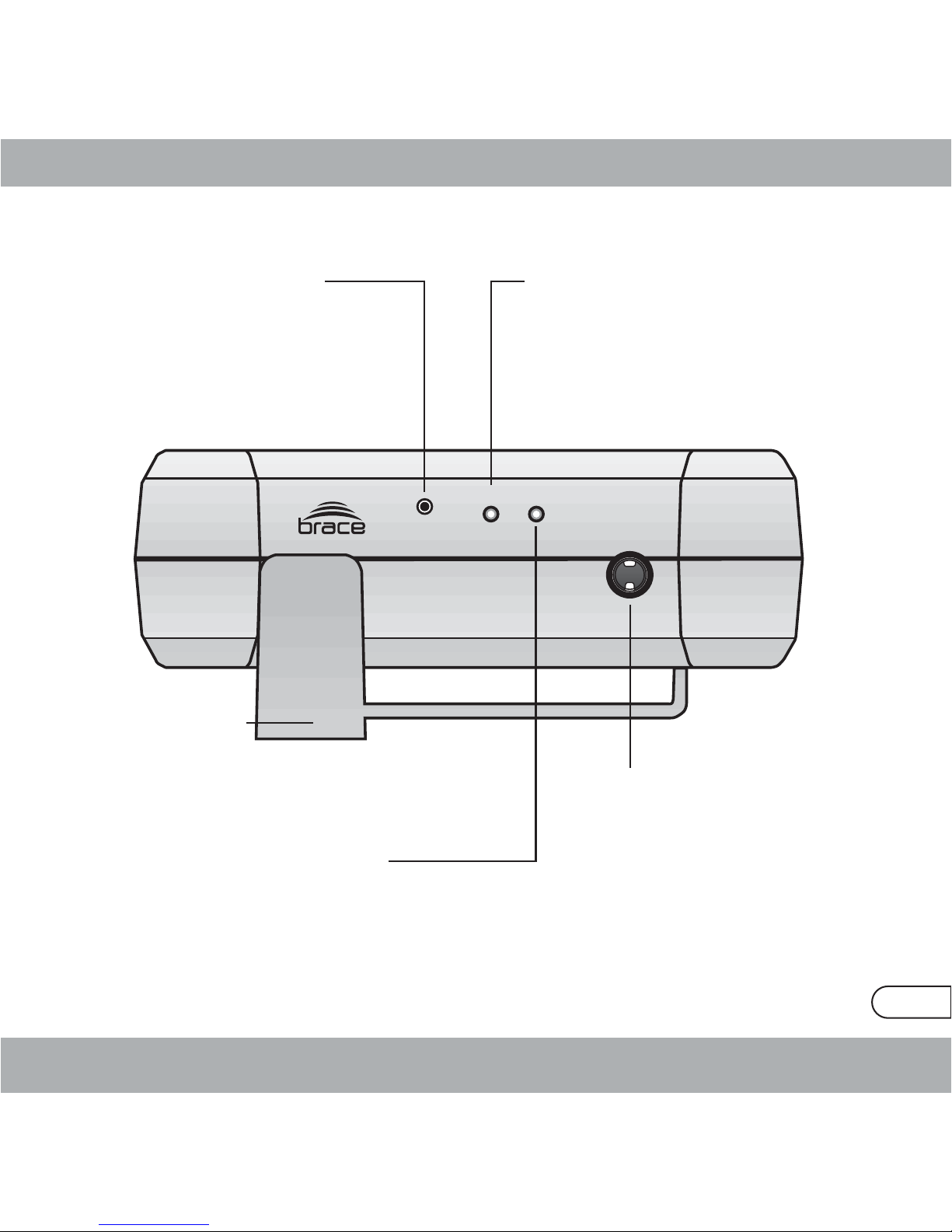
Transmier
FN LINK LOW B
Transmier (Tx / Gray Unit)
1. Funcon Buon (”FN”)
Press the Funcon Buon to iniate
Mang Funcon if necessary. (see secon,
Changing Channels). Use the end of an
unfolded paper clip to access the buon.
5. Belt Clip (”BC”)
2. Link LED (”LINK”)
The LED lights solid when a wireless
connecon is made between the Tx and Rx
units, and pulses when finding a connecon
to one of over 65,000 channels (!)
4. Audio In Jack (”That Hole”)
Plug the 1/8” connector on the
included cable into the Audio In
Jack, and the 1/4” connector into
your guitar. This jack also acts as a
switch, turning the unit on when
the plug is inserted.
Unplug the cable to turn the unit
off.
3. Low Baery LED (”LOW B”)
When the baeries are low (less than 15
minutes of baery life), the Low Baery LED
lights solid.

FN
LINK LOW B
6
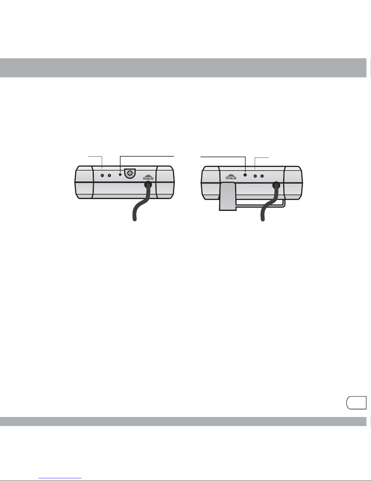
Receiver
Receiver (Rx / Dark Green Unit)
3. Funcon Buon
(”FN”)
Press the Funcon Buon to
iniate Mang Funcon if
necessary. (see secon,
Changing Channels). Use the
end of an unfolded paper clip to
access the buon.
1. Link LED (”LINK”)
The LED lights solid when a
wireless connecon is made
between the Tx and Rx units,
and pulses when finding a
connecon to one of over
65,000 channels (!)
2. Low Baery LED
(”LOW B”)
When the baeries are low
(less than 15 minutes of
baery life), the Low Baery
LED lights solid.
4. Audio Out Jack (”The Other Hole”)
Plug the 1/8” connector on the included
cable into the Audio Out Jack, and the 1/4”
connector into your amplifier. This jack also
acts as a switch, turning the unit on when
the plug is inserted. Unplug the cable to
turn the unit off. Before plugging the Rx into
your guitar amp, turn the amplifier volume
all the way down. This will prevent feedback
or unwanted pops.
5. Jack for AC Adapter
Use only the Brace Audio supplied or
recommended power supply.
Approved replacement AC Adapters are listed at
www.braceaudio.com/Products
3V DC, 500mA Regulated AC Adapter
Polarity :Tip Posive (+)
Adapter size 2.3 mm outside diameter, 0.7 mm
inside diameter
Rx (Dark Green)
Tx (Gray)
“I am so beautiful.. to me...”
!
7
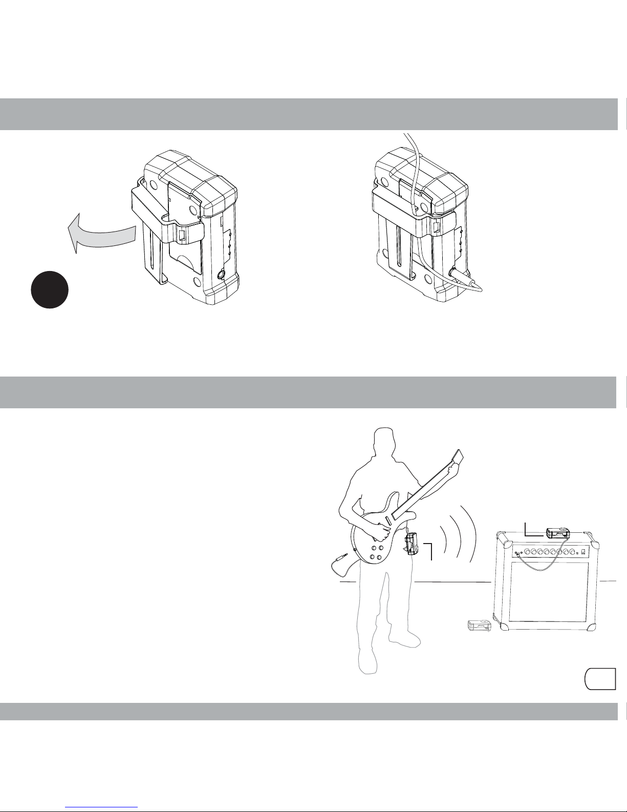
Cable Strain Relief
Placement of Tx / Rx Units
Remove belt clip on Transmier. Thread cable through the notch in the clip, then
snap the belt clip back onto Transmier. This will provide strain relief for the cable.
Transmier (Tx / Gray Unit)
Place Tx unit on your hip - on the side of the
guitar neck, or away from the guitar output.
The rounded dome should point away from
your body.
Receiver (Rx / Dark Green Unit)
The RX unit can be placed on the amplifier or
on the stage.
Alternavely you could place the RX unit
as the first device in-line with your stomp boxes.
You’ll get the same great performance with the
placement and set-up that works best for you.
Performance may vary depending on locaon & environment. Not to menon how much you pracce...
Alternate
Placement
Rx

8
Low Baery LED
Changing Baeries
AC Adapter
The low baery LED will turn on when the baery power is at a minimum,
indicang 15 minutes or less leof baery life. When this occurs, follow the
instrucons under Changing Baeries.
To change baeries on either the Transmier or Receiver, remove the cover
plate on the back of the unit. Press down at the top and slide the cover open.
Each unit takes two “AA”baeries. Be sure to observe the proper polarity of
the baeries.
The DWG-1000 Receiver (Rx) can be operated with the supplied AC adapter
or two AA baeries. The provided AC adapter accepts input voltages from
110V - 220V. Connect the AC adapter‘s power cord to the Rx AC adapter
power input jack.
If you always intend to power the Rx from
the AC Adapter, remove the baeries.
FN LINK LOW B
FN
LINK LOW B
Funcon
“Link LED” “Link LED”
Rx Tx
9
Changing Channels
DWG-1000 system components are linked at the factory. In the rare event that
the Link LEDs on both the Transmier and Receiver units connue to blink and
fail to light solid, your DWG-1000 might be sharing channels with another
wireless system. The RF Mang feature enables you to switch to one of over
65,000 non-compeng channels. To switch channels, use an unfolded paper
clip to depress the Funcon Buons.
1) Plug guitar cables into each unit to turn them on, (snicker) and place
the Rx and Tx units close to each other. (Don’t stare. They’re shy...)
2) On the Receiver unit (RX/Dark Green) press in the Funcon Buon and
hold unl the Link LED blinks rapidly. Release the buon at this point. RF
mang has been iniated now on the RX unit.
3) On the Transmier unit (Tx/Gray), press in the Funcon Buon and hold
unl the Link LED blinks rapidly. Release the buon at this point. The TX
unit will now negoate with the RX unit and a new random channel will be
assigned. When finished, both RX and TX LEDs will light solid indicang
that the units are now correctly working on the new channel.
To exit RF Mang mode, turn the units off(unplug the cables) and they will retain
their new mang ID; even aer changing baeries. Future frequencies may vary
based on locaon, so taoos are not advised, though flowers and breakfast in
bed would be a nice touch.
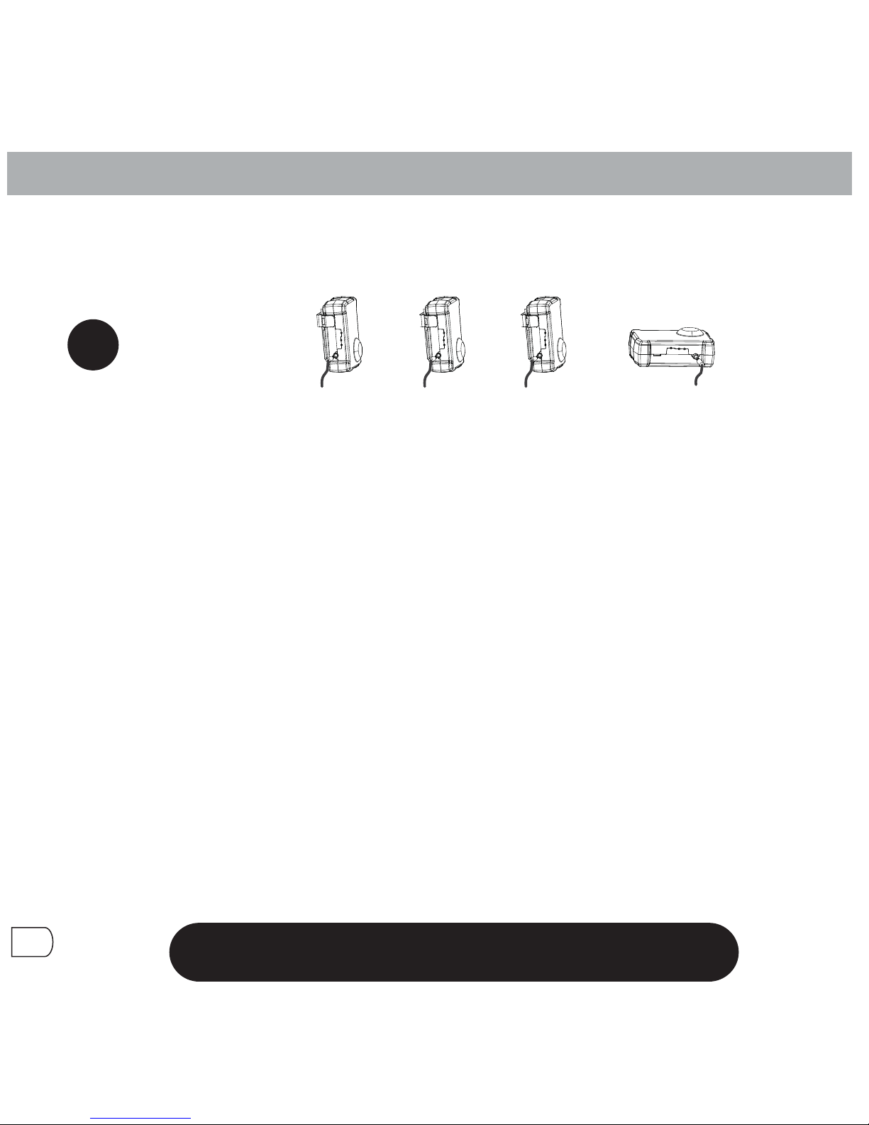
Tx - 1c Tx - 1b Tx - 1a
Oh, grow up!
Rx-1
etc...
Plug cables into
all units first!
!
10
Configuring Mulple Transmiers
1. Place Tx-1a close to the receiver. Push and hold the paperclip buon on
transmier unit 1a unl the link LED blinks rapidly.
2. Place Tx-1b close to the receiver. Push and hold the paperclip buon on
transmier unit 1b unl the link LED blinks rapidly.
3. Connue for all remaining transmiers you want to configure...
4. Push and hold the paperclip buon on the single receiver unit unl the link LED
blinks rapidly. You must press the Rx buon last, or things won’t work!
5. Wait unl the link LED's go solid on all the units and then you are done.
All the transmit units are now bonded to the single receiver; even aer they are
shut off. If you change baeries, they will sll be bonded. The bonded channel
number is a random value of 1 - 65,536. This allows mulple band members to
bond their transmiers to their own receivers without worrying that there will be
a conflict on a band-mate’s channel.
Please note: You cannot use more than one of the bonded transmiers at a
me. If you do, two (or more) bonded channels will collide with each other. Life -
as we know it - could come to and end, and it would be your fault. And future
authories will find out who you were, because you registered your rig at
www.braceaudio.com.So, one axe at a me, please. The World thanks you...
Up to 12 DWG-1000 TX transmiers can be associated, or bonded, to each
receiver. But it’s only one Transmier at a me! This is very cool for having
your enre rack of axes hooked-up and ready to go; live or in the studio.
Always unplug the transmier(s) that you are NOT using,
to prevent problems when switching to your next axe!

made in the USA 11
Technical Specificaons
Company Contact Informaon
Transmier (Tx)
RF Output Power: 16 dBm Wireless Frequency: 2.4 GHz, FHSS
Maximum Input Level: 1V RMS Input Impedance: 600K ohm
THD: < 2% @ 800 mV pp 1kHz tone Operang Power Voltage: 3.0V Nominal
S/N Rao: 100 dB Audio Frequency Response: 15Hz - 15 kHz
Baery Life: 5 hours (AA size baery) Low Baery Alert: 15 minutes of life le
Input Jack: 1/8” (3.5mm), mono Antenna: Internal
System Gain: 1:1 (unity) Tx’s per Receiver (one at a me): 12
Receiver (Rx)
Wireless Frequency: 2.4 GHz, FHSS Baery Life: 7 hours (AA size baery)
AC Adapter: 110V-220V - 3V, 500mA Receivers operang at same me: 6
Output Jack: 1/8” (3.5mm), mono Cables: 1/8” - 1/4”
• For technical assistance or support, please contact your local dealer or go to
www.braceaudio.com for more informaon. Don't forget to register your
product on-line too!
Brace Audio
15600 NE 8th St, Suite B1, 287
Bellevue, WA 98008

12
Declaraon of Conformity
Declaration of Conformity
Brace Audio Corporation declares that the equipment described in this document
is in conformance with the requirements of the European council Directives
1999/519/EC, 2006/95/EC, 2004/108/EC and 1999/5/EC, listed below:
EN 300 328 V1.7.1 (2006-10),
EN 301 489-1 V1.8.1 (2008-04),
EN 301 489-17 V1.3.2 (2008-04),
EN 60065:2002 + A1:2006,
EN 50392:2004
All essential radio test suites have been carried out.
_____________________________________________________________________
Product Description: Digital Wireless Guitar System
Model: DWG1000
This declaration is issued under the sole responsibility of Brace Audio Corporation
and, if applicable, their authorized representative(s)
.
July 31, 2008
David Stokes, CEO/President
!
0681

13
For Compliance Information ONLY, Contact:
European Contact: Hyperactive
Neukirchner Str. 18
65510 Hunstetten
Germany
USA Contact: Brace Audio Corporation
15600 NE 8th St. Suite B1, 287
Bellevue, WA 98008
USA
Notified Body: Eurofins ETS Product Service GmbH
Storkower Strasse 38c
D-15526 Reichenwalde b. Berlin
Germany
Identification Number: 0681
Test Lab: MiCOM Labs, Inc,
440 Boulder Court
Suite 200
Pleasanton, CA 94566
USA
Brace Audio Corporaon
15600 NE 8th St, Suite B1, 287
Bellevue, WA 98008 USA
www.braceaudio.com

14
Usage Noce
Usage notice:
The DWG-1000 transmits wireless signals and should only be used as instructed.
Failure to use as instructed could expose the user to higher levels of radio
emissions, even though the transmission levels of the DWG-1000 are low. The
user should in no way try to alter the radio settings as provided by Brace Audio.
Changes or modifications not expressly approved by Brace Audio could void the
user's authorization to operate the equipment.
This product is intended for indoor use only, in that outdoor use may be in
violation of local or country usage restrictions. Consult your local rules regarding
outdoor use before using product outdoors.
Product Support: For Technical Support or for help not available in this manual,
see the brace audio website at www.braceaudio.com
This device complies with Part 15 of the FCC Rules. Operation is subject to
the following two conditions: (1) this device may not cause harmful interfer-
ence, and (2) this device must accept any interference received, including
interference that may cause undesired operation.
This Class B digital apparatus complies with Canadian ICES-003.
Cet appareil numérique de la classe B est conforme à la norme NMB-003 du
Canada.

15
FCC Notice (United States):
This equipment has been tested and found to comply with the limits for a Class B
digital device, pursuant to part 15 of the FCC rules. These limits are designed to
provide reasonable protection against harmful interference in a commercial
installation. This equipment generates, uses and can radiate radio frequency
energy and, if not installed and used in accordance with the instructions, may
cause harmful interference to radio communications. However, there is no guaran-
tee that interference will not occur in a particular installation. If this equipment does
cause harmful interference to radio or television reception, which can be deter-
mined by turning the equipment off and on, the user is encouraged to try to correct
the interference by one or more of the following measures:
• Reorient or relocate the receiving antenna.
• Increase the separation between the equipment and the receiver.
• Connect the equipment into an outlet on a circuit different from that to
which the receiver is connected.
• Consult the dealer or an experienced radio/TV technician for help.
Industry Canada Notice (Canada):
This Class B digital apparatus complies with Canadian ICES-003.
Cet appareil numérique de la classe B est conforme à la norme NMB-003 du
Canada.
CE Notice (European Notice):
The Conformité Européne symbol found on this product indicates compliance to
the EMC Directive and the Low Voltage Directive of the European council Direc-
tives 1999/519/EC, 2006/95/EC, 2004/108/EC and 1999/5/EC, listed below:
EN 300 328 V1.7.1 (2006-10), EN 301 489-1 V1.8.1 (2008-04), EN 301 489-17
V1.3.2 (2008-04), EN 60065:2002 + A1:2006, EN 50392:2004

www.braceaudio.com
© 2010 - Brace Audio Corporation
LIMITED WARRANTY
Brace Audio Corporation warrants to the original end user purchaser (”You”) that, for a period of one year, (the
“Warranty Period”), your Brace Audio Corporation product will be free of defects in materials and workmanship
under NORMALintended use. Warranty coverage does not extend to accident or abuse including, but not limited
to, dropping, stomping, smashing, lighting on fire or other rock-n-roll histrionics. Your exclusive remedy and Brace
AudioCorporation’sentireliabilityunderthiswarrantywillbeforBraceAudioCorporation,atitssoleoption,torepair
or replace the product.All conditions of merchantability or fitness for a particular purpose and implied warranties
are limited. BraceAudio Corporation disclaims for the duration of the warranty period all other express or implied
conditions, representations and warranties, including implied warranty of non-infringement. Some jurisdictions do
not allow limitations on how long an implied warranty lasts, so the above limitation may not apply to You. This
warrantygivesYouspecificlegalrights,andYoumayalsohaveotherrightswhichvarybyjurisdiction.Totheextent
notprohibitedbylaw,innoeventwillBraceAudioCorporation be liableforanylostrevenueorprofit,orforspecial,
consequential,indirect,incidentalorpunitivedamages,howevercausedregardless of the theory ofliability,arising
out of or related to the use of or inability to use the product, even if BraceAudio Corporation has been advised of
thepossibility ofsuch damages.In no event will BraceAudio Corporation’sliability exceed the amount paid by you
for the product from direct, indirect, special, incidental, or consequential damages resulting from the use of the
product, its accompanying accessories, product packaging, or its documentation. Brace Audio Corporation does
notofferrefundsforanyproduct.Theforegoinglimitationswillapplyevenifanywarrantyorremedyprovidedunder
this Section fails of its essential purpose. Some jurisdictions do not allow the exclusion or limitation of incidental or
consequential damages, so the above limitation or exclusion may not apply toYou.
In the unlikely occurrence the product proves defective during the warranty period please visit our web page at
http://www.braceaudio.com forthemost up-to-date method ofreturn.With a validated warrantyclaim,BraceAudio
Corporationwillhavetheoptiontorepairorreplacewithneworrefurbishedunits.Shouldtheproductbediscontinued
and the unit cannot be repaired or replaced, BraceAudio Corporation at its sole option can choose to replace the
product with a next generation product of similar capability. Be sure to keep your proof of purchase as it will be
required to ensure proper warranty handling. Warranty return requests cannot be processed without proof of
purchase.Youareresponsibleforshippingchargesrelatedtothedefective product(s) to BraceAudioCorporation.
BraceAudioCorporationwillpayforGroundshippingfromBraceAudioCorporationbacktoYouonly.Wehopeyou
appreciate that we referred to you as “You” thoughout this onerous and legally required document. You Rock!
Table of contents
Popular Amplifier manuals by other brands


Matrix Audio
Matrix Audio M-Stage HPA-3B manual

Nikrans
Nikrans MA-250GW installation guide

RCF
RCF ES3160 Brochure & specs

Crown
Crown Macro-Tech MA-3600VZ Architectural & engineering specifications

AMC
AMC 2N100-5 Instructions for installation and operation

Box-Design
Box-Design Pro-Ject Pre Box DS2 Digital Instructions for use


