Branson 2000 series User manual

Manual Change Information
At Branson, we strive to maintain our position as the leader in ultrasonics plas-
tics joining, cleaning and related technologies by continually improving our cir-
cuits and components in our equipment. These improvements are incorporated
as soon as they are developed and thoroughly tested.
Information concerning any improvements will be added to the appropriate
technical documentation at its next revision and printing. Therefore, when
requesting service assistance for specific units, note the Revision information
found on the cover of this document, and refer to the printing date which
appears at the bottom of this page.
Copyright
NOTE
i
i
Loctite is a registered trademark of Henkel Corporation U.S.A.
Other trademarks and service marks mentioned herein are held
by their respective owners.
©BRANSON Ultrasonics Corporation Printed in U.S.A. June 2014

100-214-226 Rev. 10
Foreword
Congratulations on your choice of a Branson Ultrasonics Corporation system!
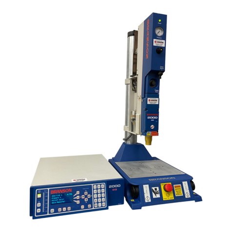
The Branson 2000-Series system is process equipment for the joining of plastic parts using ultra-
sonic energy. It is the newest generation of product using this sophisticated technology for a vari-
ety of customer applications. This Instruction Manual is part of the documentation set for this
system, and should be kept with the equipment.
Thank you for choosing Branson!
Introduction
Thismanualisarrangedintoseveralstructuredchapters which will help you find theinformation
you may need to know to safely handle, install, set up, program, operate, and/or maintain this
product. Please refer to the Table of Contents and/or the Index of this manual to find the infor-
mation you may be looking for. In the event you require additional assistance or information,
please contact our Product Support department (see page 52 for information on how to contact
them) or your local Branson representative.
2000
Series
Installation Guide


100-214-226 Rev. 10 i
2000 Series
Installation Guide
Table of Contents
About this Installation Guide - - - - - - - - - - - - - - - - - - - - 1
Safety First - - - - - - - - - - - - - - - - - - - - - - - - - - - - - 2
Handling and Unpacking - - - - - - - - - - - - - - - - - - - - - - 3
Unpack the Power Supply - - - - - - - - - - - - - - - - - - - - 3
Unpack the Stand or Actuator - - - - - - - - - - - - - - - - - - 3
Stand (actuator on a base) - - - - - - - - - - - - - - - - - - - - 4
Stand (actuator on a hub) - - - - - - - - - - - - - - - - - - - - 5
Actuator (alone) - - - - - - - - - - - - - - - - - - - - - - - - - 6
Take Inventory of Small Parts - - - - - - - - - - - - - - - - - - 7
Cables- - - - - - - - - - - - - - - - - - - - - - - - - - - - - - 8
Installation Requirements - - - - - - - - - - - - - - - - - - - - - 9
Location - - - - - - - - - - - - - - - - - - - - - - - - - - - - - 9
Environmental Specifications- - - - - - - - - - - - - - - - - - - 9
Electrical Input Power Ratings - - - - - - - - - - - - - - - - - -10
Factory Air - - - - - - - - - - - - - - - - - - - - - - - - - - - - -17
Air Filter - - - - - - - - - - - - - - - - - - - - - - - - - - - - -17
Pneumatic Tubing and Connectors - - - - - - - - - - - - - - - -17
Pneumatic Connections to Actuator ae/aed/aef - - - - - - - - - -18
Pneumatic Connections to Actuator ao/aod/rp - - - - - - - - - -18
Mounting the Stand (Actuator on Base)- - - - - - - - - - - - - -18
Leveling Fixture Setup - - - - - - - - - - - - - - - - - - - - - -19
Preliminary Setup - - - - - - - - - - - - - - - - - - - - - - -19
Setup - - - - - - - - - - - - - - - - - - - - - - - - - - - - -22
Horn, Part, and Fixture Alignment - - - - - - - - - - - - - - -23
Mounting the Stand (Actuator on Hub-mounted column)- - - - - -24
Actuator (alone) - - - - - - - - - - - - - - - - - - - - - - - - -25
Mount the Power Supply - - - - - - - - - - - - - - - - - - - - -27
Interconnect between Power Supply and Actuator - - - - - - - -27
Input Power (Main)- - - - - - - - - - - - - - - - - - - - - - - -28
Output Power (RF Cable) - - - - - - - - - - - - - - - - - - - -29
Start Switch Connection (Automation) - - - - - - - - - - - - - - -30

ii 100-214-226 Rev. 10
Serial (RS-232) Port Connector- - - - - - - - - - - - - - - - - -31
Parallel Printer Connector - - - - - - - - - - - - - - - - - - - -31
User I/O Interface - - - - - - - - - - - - - - - - - - - - - - - -32
Input Power Plug- - - - - - - - - - - - - - - - - - - - - - - - -34
User I/O DIP Switch (SW1)- - - - - - - - - - - - - - - - - - - -35
Guards and Safety Equipment - - - - - - - - - - - - - - - - - - -36
Emergency Stop Control - - - - - - - - - - - - - - - - - - - - -36
Rack Mount Installation- - - - - - - - - - - - - - - - - - - - - - -38
Assemble the Acoustic Stack - - - - - - - - - - - - - - - - - - -40
For a 15 kHz System
For a 20kHz System
For a 30kHz System
For a 40kHz System
Stack Assembly Torque Tables- - - - - - - - - - - - - - - - - -43
Connecting Tip to Horn- - - - - - - - - - - - - - - - - - - - - -44
Installing the Ultrasonic Stack in the Actuator - - - - - - - - - - -44
15 kHz, 20 and 30 kHz Stacks - - - - - - - - - - - - - - - - -44
40 kHz Stacks- - - - - - - - - - - - - - - - - - - - - - - - -46
Mounting the Fixture on the Branson Base - - - - - - - - - - - -47
Converter Duty Cycle and Cooling - - - - - - - - - - - - - - - -48
Testing the Installation, 4 Line Display - - - - - - - - - - - - - - -50
Testing the Installation, Touch Screen - - - - - - - - - - - - - - -51

2000 Series
Installation Guide About this Installation Guide
100-214-226 Rev. 10 1
About this Installation Guide
This installation guide is to help the installer with the basic installation and setup of your new 2000-
series welder. You will still need the product’s manuals. This guide will bring the readerto the point
at which the system is functionally “ready to weld”.

Safety First
2100-214-226 Rev. 10
Safety First
Branson is concerned for your safety and for the successful installation and operation of this sys-
tem. Please read and heed all safety symbols listed in this guide and heed all safety signs on the
products.
WARNING
Indicates a potentially hazardous situation which, if not avoided, could result in death or
serious injury.
CAUTION
!
Indicates a potentially hazardous situation which, if not avoided, may result in minor or
moderate injury.
CAUTION
Indicates a potential hazardous situation which, if not avoided, may result in property
damage.
NOTE
i
i
A Note in the guide or manual contains important informationthat you should observe. It does
not involve personal injury but may involve additional work or modification if you ignore it.
International safety labels are found on the power supply and the actuator as well. Those that are
of importance during Installation of the system are identified in the figures in this guide and in the
manuals.

2000 Series
Installation Guide Handling and Unpacking
100-214-226 Rev. 10 3
Handling and Unpacking
If there are any visible signs of damage to the shipping containers or the product, or you later dis-
cover hidden damage, NOTIFY YOUR CARRIER IMMEDIATELY. Save the packing material.
1. Unpack the 2000-series components as soon as they arrive. Refer to the following procedures.
Verify you have all of the equipment ordered. Some components are packed inside other boxes.
2. Inspect the controls, indicators, and surfaces for signs of damage.
3. Save all packing material, including the pallets and wood spacer blocks.
Unpack the Power Supply
Power supplies are shipped in a cardboard carton. It weighs approximately 40 lbs.
1. Open the box, remove the two foam top packing halves and lift the power supply out.
2. Remove the toolkit(s) and other components shipped with the power supply. These items may be
shipped in small, separate boxes, or underneath the power supply in the box.
3. Save the packing material; evaluation systems will be returned using this packing material.
Unpack the Stand or Actuator
The stand(or actuator) is heavy and packed in aprotective shipping container. The actuator toolkit
is packed with the actuator. A booster, converter and other components may be packed inside the
shipping container (depending on the equipment ordered).
• Stands are shipped on a wooden pallet with a cardboard box cover.
• Actuators (alone) are shipped in a rigid cardboard box using protective foam shells for support.
Figure 1 Linear Encoder is sensitive; Do Not Handle it!
CAUTION
The linear encoder (on the left side of the actuator) is very sensitive. Do not use the linear
encoder assembly as a hand-hold, allow no impact on it, and do not place any weight on it.
Linear encoder
on left side of
Actuator (2000d and f only)
Do not touch, bump,
or use as a handle
Actuator on stand shown,
left side view

Handling and Unpacking
4100-214-226 Rev. 10
Depending on which one of the following options applies to you, unpack the Branson actuator
assembly:
Stand (actuator on a base)
CAUTION
!
Heed the “This End Up” arrows and the “Open Top First” instructions. The packaging is
designed to be removed from the assemblies from an upright orientation only.
Figure 2 Unpacking the Stand (Actuator on a Base); right-side view of Stand
1. Move the shipping container close to the intended installation location, leave it on the floor.
2. Open the top of the box. Remove the insert from the top of the protective box, which may contain
the booster, converter, and the toolkit.
3. Remove the staples at the bottom of the protective box. Lift the protective box off the pallet.
CAUTION
!
Column and column are under spring tension. Do NOT disassemble the column from the
stand. Always keep the column support clamped together.
NOTE
i
i
When making height adjustments, carefully and slowly release the clamps to control the
motion, and hold the stand to prevent sudden movements or injury.
wood block
for shipping
Actuator
Column
Base
Actuator
Support
Spring Swivel
6-1/2 in.
Tool Kit
Converter
Booster
18in.
Protective
Box
wood block
for shipping
53in.
32-1/2in.
Insert
Box

2000 Series
Installation Guide Handling and Unpacking
100-214-226 Rev. 10 5
4. Cut the two packing straps around the base and pallet. Pry off the two wooden shipping blocks (to
the rear of the base) which prevent the base from sliding on the pallet.
5. The stand can now be moved into its desired location by sliding it off the pallet. Stands have a lifting
hook for the use of overhead hoists to lift the assembly in place.
6. Remove the block of wood between the base and the column support by carefully loosening the
two column clamps (allowing the actuator to rise slightly, but not allow sudden movements) and
then cutting the shipping tape on the block of wood. RETIGHTEN THE COLUMN CLAMPS.
7. Unpack the toolkit from the insert box, and other parts (converter, booster, etc.) that may have
shipped with the stand. Save the packing material.
8. Go to Take Inventory of Small Parts. See Table 2.
Stand (actuator on a hub)
Figure 3 Unpacking the Stand (Actuator on a Hub); Hub shown separately
CAUTION
Heed the “This End Up” arrows and the “Open Top First” instructions. The packaging is
designed to be removed from the assemblies from an upright orientation only.
1. Move the shipping container close to the intended installation location, leave it on the floor.
2. Cut the two vertical packing straps, and open the top of the box. Remove the insert from the top of
the box, which can contain the booster, converter, and the toolkit. Set the insert box aside.
3. Remove the staples at the bottom of the protective box. Lift the protective box off the pallet. Flatten
the box and lay it next to the pallet (you will lay the stand on it soon).
CAUTION
!
The unit may tip over. Stabilize the stand using the lifting hook or an assistant.
Converter
Tool Kit
Booster
6-1/2in.
18in.
Shipping
Strap
53 in.
Block of wood
for shipping
32-1/2in.
Insert Box
Protective
Box
Hub
(shipped in place
on column, on pallet)
Two Hub Bolts
(loosen to remove
Hub from Column using
Note: Hubs may be lag-bolted to the
pallet for shipping purposes.
a 5/16” allen wrench)

Handling and Unpacking
6100-214-226 Rev. 10
4. Cut the packing strap securing the actuator support to the pallet.
CAUTION
!
Column and support are under spring tension. Do NOT disassemble the column from the
stand. Always keep the column support clamped together.
NOTE
i
i
When making height adjustments, carefully and slowly release the clamps to control the
motion, and hold the stand to prevent sudden movements or injury.
5. Removethe block(s)ofwoodbetweenthebaseandthesupportby slowlylooseningthetwo column
clamps (allowing the stand to rise slightly) and then cutting the shipping tape on the block of wood.
RETIGHTEN THE COLUMN CLAMPS.
6. Loosen the two hub bolts (for column clamping) on the hub.
7. Lift the actuator and column from the pallet. Carefully lay the stand on its right side (NOT ON THE
SIDE WITH THE LINEAR ENCODER, if present).
8. Remove the hub from the pallet and set it aside. Some hubs are bolted to the pallet from the top.
9. Unpack the converter, booster and toolkit from the insert box. Save the packing material, including
the blocks of wood.
10. Go to Take Inventory of Small Parts. See Table 2.
Actuator (alone)
The actuator, if shipped alone, is assembled and ready to install.
NOTE
i
i
In a custom installation, the actuator must be mounted on an I-beam or other rigid structure.
The mounting surface must be flat within 0.004 in (0.1mm) Total Indicator Reading, in a
tolerance zone of 16 x 3.5 in (410 x 90 mm).
Move the shipping container close to the intended installation location, leave it on the floor.
1. Open the top of the cardboard box, remove the insert from the top of the box and set it aside.
2. The tool kit, mounting bolts, and converter and/or booster are shipped with the actuator but in
separate shipping box(es). Unpack the converter, booster, toolkit and bolts from their packages.
3. Save the packing material.
NOTE
i
i
The packaging may also include the converter and/or booster, if ordered.

2000 Series
Installation Guide Handling and Unpacking
100-214-226 Rev. 10 7
Figure 4 Ultrasonic Converter and Booster
Take Inventory of Small Parts
Table 2 Small Parts Included (=x) with Power Supply and/or Actuator Assemblies
NOTE
i
i
Part numbers for spares are found in the Instruction Manuals.
*not used with 2000f actuator
Table 1 Actuator Weights, Approximate (lbs)
Actuator Model Actuator on a Base Actuator on a Hub Actuator Alone
ao 174 134 39
aod 176 136 40
ae 170 130 35
aed 172 132 36
aef 180 140 38
Part or Kit 2000 Power Supply Actuator
15kHz 20kHz 30kHz 40kHz Stand (Base) Stand (Hub) (alone)
T-Handle Wrench x x x
Mylar Washer Kit x x x
Silicone Grease x
Actuator Mtg. Bolts x
15kHz Spanners (2) x
20kHz Spanners (2) x
30kHz Spanners (2) x
40kHz Spanners (2) x
40kHz Sleeve ordered part ordered part ordered part
40kHz Sleeve Spanner ships w/ Sleeve ships w/ Sleeve ships w/ Sleeve
Fixture Bolts and
Washer x
M8 Allen Wrench x
5/64 in. Allen Wrench* x x x
Converter Booster

Handling and Unpacking
8100-214-226 Rev. 10
Cables
Twocablesconnectthepower supplyandactuator:theactuator interfacecable,andthe RFcable.
Ifthesystem is tobeautomated, youmayalsoneedaJ911startcableand auserI/O cable.Check
your invoice for cable types and cable lengths.
Table 3 List of Cables
CE and non CE cables are fabricated to different specifications. CE cables differ in that the pin
distance and allowable insulation creepage is controlled to more exacting tolerances.
101-241-202 Remote Pneumatic (RP) Package Cable (J924), 8’
101-241-203 Actuator Interface, 8’ (J925S)
101-241-204 Actuator Interface, 15’(J925S)
101-241-205 Actuator Interface, 25’(J925S)
101-241-206 Actuator Interface, 50’(J925S)
101-241-207 Alarm I/O, 8’(J957S)
101-241-208 Alarm I/O, 15’(J957S)
101-241-209 Alarm I/O, 25’(J957S)
101-241-258 Alarm I/O, 50’(J957S)
101-240-020 Start Cable (J911) 8’ (req PLA)
101-240-015 Start Cable (J911) 15’ (req PLA)
101-240-010 Start Cable (J911) 25’ (req PLA)
101-240-168 Start Cable (J911) 50’ (req PLA)
101-240-072 Start Cable (J913) 25’ (no PLA req)
101-240-017 RF, non-CE - 8’ (J931S)
101-240-012 RF, non-CE - 15’ (J931S)
101-240-007 RF, non-CE - 25’ (J931S) Note: Not for 30kHz or 40kHz systems
101-240-200 RF, non-CE - 50’ (J931) Note: Not for 30kHz or 40kHz systems
101-240-034 RF, non CE - 8’ (J 934)
101-240-035 RF, non CE - 15’ (J934)
101-240-081 RF, non CE - 8’ (J936S)
101-240-069 RF, non CE - 15’ (J936S)
101-240-080 RF, non CE - 25’ (J936S)
101-240-176 RF, CE - 8’ (J931CS)
101-240-177 RF, CE - 15’ (J931CS)
101-240-178 RF, CE - 25’ (J931CS) Note: Not for 30kHz or 40kHz systems
101-240-199 RF, CE - 50’ (J931C)
101-240-179 RF, CE - 8’ (J934C)
101-240-188 RF, CE - 15’ (J934C)
101-240-182 RF, CE - 20’ (J934C)
100-246-630 Ground Detect Cable
100-143-043 Printer, 6’

2000 Series
Installation Guide Installation Requirements
100-214-226 Rev. 10 9
Installation Requirements
Location
The actuator or stand may be installed in a variety of positions. The stand (mounted on a base) is
oftenmanuallyoperated,usingitsbase-mountedstartswitches,andso isinstalledat asafe(being
able to support at least 250 pounds) and comfortable workbench height (approximately 30-36
inches for seated operation, 36-42 for standing) with the operator sitting or standing in front of the
system. Stands (on hubs) are designed for use in automated systems and may be manually or
automatically loaded and unloaded.
WARNING
Stand may tip over if rotated around the axis of its column. Secure base or hub.
NOTE
i
i
The work surface on which a stand is installed must be sturdy enough to support it, and
secure enough to not tip over when the stand is adjusted during installation or setup.
The power supply may be located up to 25 feet away for the 15kHz, (50' for 20kHz, 20' for 30kHz,
and 15' for 40kHz models) from the actuator. The power supply must be accessible for user
parameter changes and settings, and must be placed in a horizontal orientation for purposes of
heat management. The power supply should be positioned so it does not draw in dust, dirt or
material via its rear fans. See Figure 5 for a dimensional drawing. All dimensions are approximate
and may vary between models.
Environmental Specifications
Table 4 Environmental Specifications
Environmental Concern Acceptable Range
Humidity 30% to 95%, non-condensing
Ambient Operating Temperature +5°C to +50°C (41°F to 122°F)
Storage / Shipping Temperature -25°C to +55°C (-13°F to +131°F);
Up to +70°C (+158°F) for 24 hours

Installation Requirements
10 100-214-226 Rev. 10
Electrical Input Power Ratings
Plug the Power Supply into a single-phase, grounded, 3-wire, 50 or 60 Hz power source. Table 5
lists the current, fuse ratings and Plugs for the various models.
Table 5 Input Power and Plug Requirements
* requires a specific 20 amp 120V receptacle
The voltages shown in the above table have the following operational tolerances:
100V - 120V nominal, 90 - 132 operational
200V - 240V nominal, 180 - 253 operational
For 15 kHz models 3300 W 200V - 240V 19 Amp Max. @ 200V / 20 Amp fuse NEMA L6-20P Plug
For 20 kHz models
1100 W 200V - 240V 7 Amp Max. @ 200V / 20 Amp fuse NEMA L6-20P Plug
1100 W 100V - 120V 13 Amp Max. @ 100V / 20 Amp fuse NEMA 5-15P Plug
2200 W 200V - 240V 13 Amp Max. @ 200V / 20 Amp fuse NEMA L6-20P Plug
3300 W 200V - 240V 19 Amp Max. @ 200V / 20 Amp fuse NEMA L6-20P Plug
4000 W 220V - 240V 21 Amp Max. @ 220V / 25 Amp fuse NEMA L6-20P Plug
For 30 kHz models 1500 W 100V - 120V* 20 Amp Max. @ 100V / 20 Amp fuse NEMA 5-20P Plug
1500 W 200V - 240V 10 Amp Max. @ 200V / 20 Amp fuse NEMA L6-20P Plug
For 40 kHz models
400 W 200V - 240V 3 Amp Max. @ 200V / 20 Amp fuse NEMA L6-20P Plug
400 W 100V - 120V 5 Amp Max. @ 100V / 20 Amp fuse NEMA 5-15P Plug
800 W 200V - 240V 5 Amp Max. @ 200V / 20 Amp fuse NEMA L6-20P Plug
800 W 100V - 120V 10 Amp Max. @ 100V / 20 Amp fuse NEMA 5-15P Plug
For 60 kHz model 200 W 100V - 120 V 3 Amp Max. @ 100V / 3 Amp fuse NEMA 5-15P Plug

2000 Series
Installation Guide Installation Requirements
100-214-226 Rev. 10 11
Figure 5 VFD 4 Line Display Power Supply Dimensional Drawing
0.45”
11.4mm 13.4”
340.1mm
17.55”
445.8mm
1.7”
43.6mm
20.6”
522.9mm
Air outlet is under
front panel
5.0” (127mm)
Desired Clearance Air Intake
5.2”
132.4mm 5.7”
144.8mm

Installation Requirements
12 100-214-226 Rev. 10
Figure 6 Touch Screen Power Supply Dimensional Diagram
0.45”
11.4mm 13.4”
340.1mm
17.55”
445.8mm
1.7”
43.6mm
20.6”
522.9mm
Air outlet is under
front panel
5.0” (127mm)
Desired Clearance Air Intake
5.2”
132.4mm 5.7”
144.8mm
20 %
100 %
80 %
60 %
40%
0 %
Reset
Test

2000 Series
Installation Guide Installation Requirements
100-214-226 Rev. 10 13
Figure 7 ae/aed Actuator Dimensional Drawing
machined mounting
surfaces (3 places)**
**These three mounting surfaces are flat
within 0.004 in. (0.1mm) TIR, in a tolerance
zone of 16 x 3.5 in. (410 x 90 mm). The
surface to which the actuator is mounted
must also have the same flatness tolerance.
SECTION A-A
BASE (OPTIONAL)
54 mm 70 mm
127 mm 140 mm
33 mm 39 mm
75 mm
24 mm
97 mm
18 mm
64 mm 70 mm
HORN WIDTH AND LENGTH WILL VARY WITH EACH DESIGN
AA
43.0
1092mm

Installation Requirements
14 100-214-226 Rev. 10
Figure 8 aef Actuator Dimensional Drawing
BASE (OPTIONAL)
SECTION A-A
AA
51.0
1295mm
48"
54 mm 70 mm
127 mm 140 mm
33 mm 39 mm
75 mm
24 mm
97 mm
18 mm
64 mm 70 mm
HORN WIDTH AND LENGTH WILL VARY WITH EACH DESIGN
machined mounting
surfaces (3 places)**
**These three mounting surfaces are flat
within 0.004 in. (0.1mm) TIR, in a tolerance
zone of 16 x 3.5 in. (410 x 90 mm). The
surface to which the actuator is mounted
must also have the same flatness tolerance.
Other manuals for 2000 series
2
Table of contents
Other Branson Welding System manuals

