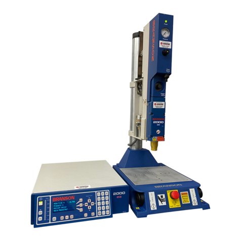
Branson 900IW+ Series User manual

100-413-028
900IW-F Series
Integrated Welders
Software Version 1.07
BRANSON
Ultrasonics
Corporation
41 Eagle Road
Danbury, CT 06813-1961
(203) 796-0400
Operator's Manual

Manual Change Information
At Branson, we strive to maintain our position as the leader in ultrasonic
plastics joining, cleaning and related technologies by continually
improving circuits and components in our equipment. These
improvements are incorporated as soon as they are developed and
thoroughly tested.
Information concerning any improvements will be added to the
appropriate manual section(s) at the next printing. Therefore, when
requesting service assistance for specific units, refer to the printing date
which appears in the lower right corner of this page.
Branson Ultrasonics Corporation Equipment is manufactured under
one or more of the following U.S. patents:
3,441,875
3,608,648
3,679,526
3,752,381
3,833,163
3,939,033
3,469,221
3,614,484
3,697,357
3,764,442 3,848,792
3,945,618
3,573,781
3,619,671
3,698,408
3,785,910
3,852,144
3,946,280
3,586,122
3,628,071
3,699,719 3,790,059
3,863,826
3,955,740
3,586,589
3,645,504
3,721,833
3,791,569 3,873,859
4,006,707
3,601,084
3,649,420
3,734,805
3,808,080
3,917,146
4,016,436
3,602,421
3,666,599
3,737,361
3,813,006
3,920,504
4,313,778
3,607,580
3,666,602
3,752,380
3,813,021
3,921,015
Processes described in this publication are covered by one or more
of the following U.S. patents:
3,401,446 3,577,292 3,765,973 3,899,116 3,969,544 3,981,759
3,563,822 3,595,453 3,893,223 3,966,520 3,972,758
© BRANSON ULTRASONICS CORPORATION
11/90
Printed in U.S.A
Loctite® is a registered trademark of Loctite Corporation, Newington, CT 06111.

Limited Warranty
Each product manufactured by Branson is guaranteed to be free from
defects in workmanship and material for thirty six (36) months from the
date of invoice. This warranty does not apply to any product which has
been subjected to misuse, misapplication, neglect (including without
limitation, inadequate maintenance), accident, or improper installation,
modification, adjustment or repair, or use with an improperly tuned horn.
Products supplied by Seller, but manufactured by others are warranted
only to the extent of the manufacturer's warranty. The guarantee period
for certain product lines will be extended at the discretion of Branson.
This warranty does not apply to horn surface wear, which is a normal
occurrence and develops over time in the operation of ultrasonic
equipment.
Metal to metal contact applications are to be limited to less than 1.5
seconds exposure time for 20 kHz welding equipment.
The warranty of converters is limited to a one-time, no-charge replacement
within the guarantee period.
Disclaimer of Warranty
The foregoing warranty constitutes Seller's only warranty in connection
with this sale, and is in lieu of all other warranties expressed or implied,
written or oral: THERE ARE NO IMPLIED WARRANTIES OF
MERCHANTABILITY OR FITNESS OF ANY PRODUCT FOR A PARTICULAR
PURPOSE.
Exclusive Remedy
SELLER'S LIABILITY SHALL BE LIMITED TO REPAIRING OR REPLACING
THE PRODUCT FOUND BY SELLER TO BE DEFECTIVE OR
NON-CONFORMING, OR, AT SELLER'S OPTION, TO REFUNDING THE
PURCHASE PRICE OF SUCH PRODUCT. At Seller's request, Buyer shall
send, at Buyer's expense, any allegedly defective product to the factory
where it was manufactured. The remedy set forth above is exclusive. The
repair or replacement of the product, or refund of the purchase price,
constitutes fulfillment of all liabilities of Seller to Buyer under the
warranties above-mentioned, whether based on contract, negligence of
any kind, strict liability or tort, or otherwise with respect to or arising out
of product furnished hereunder.
Warranty

Limitation of liability
Buyer expressly agrees that, notwithstanding any other provision of this
contract, under no circumstances shall Seller's total aggregate liability
exceed the price paid for the product if the liability results from the
following:
1.
The performance, failure to perform or breach of Seller's obligations
herein
2.
Any activity undertaken by Seller with regard to equipment and
services covered by this contract
3.
All actions based on negligence of any kind, strict liability or tort on
the part of Seller or its suppliers
4.
Otherwise.
BUYER EXPRESSLY AGREES THAT SELLER WILL NOT BE LIABLE UNDER
ANY THEORY OF LIABILITY FOR ANY DIRECT, SPECIAL, INCIDENTAL
OR CONSEQUENTIAL DAMAGES, INCLUDING, WITHOUT LIMITATION,
THE LOSS OF USE, INCOME, PROFITS OR PRODUCTION; INCREASED
COST OF OPERATION; OR DAMAGE TO MATERIAL, ARISING IN
CONNECTION WITH THE SALE, INSTALLATION, USE OF, INABILITY TO
USE, OR THE REPAIR OR REPLACEMENT OF SELLER'S PRODUCTS. Buyer
shall indemnify and hold Seller harmless for any liability to Buyer's
employees, workers, contractors or any other persons beyond the
limitation provided in this section.
Limitation on Claims and Actions
Any claim by Buyer for breach of the foregoing warranty shall be deemed
waived by Buyer unless submitted to Seller in writing within thirty (30)
days from the date Buyer discovered or by reasonable inspection should
have discovered the alleged breach. Any cause of action for breach of the
foregoing warranty shall be brought within one year after the cause of
action has accrued.
Warranty
iv
9001W+

Please read before installing or using the equipment.
1. Be sure the welder is unplugged and the power switch is in the OFF
position before making any electrical connections.
2. To prevent the possibility of an electrical shock, always plug the
welder into a grounded power source.
3. If you wish to use a J911 cable, you must first have signed a Branson
Product Liability Agreement.
4. To prevent personal injury or damage to the equipment or workpiece
being welded, always hold the welder in place before releasing the
column clamps. This procedure may require two people.
5. When setting up and operating the welder, observe the following
precautions:
a.
High voltage is present. Do not operate with covers open or
removed.
b.
Do not touch a vibrating horn.
c.
Large plastic workpieces may vibrate within the audible
frequency range when welded. If this occurs, use hearing
protectors to prevent possible injury. (For further information,
refer to Appendix F "Manufacturers of Hearing Protectors.")
d.
Do not press the 'PEST switch when the converter is removed
from the welder.
6. Ensure that the cover is closed with door screws secured and that no
one is in contact with the horn when you press TEST. Automated
systems users should turn off indexing equipment for this test.
7. Be sure the welder is unplugged before setting the DIP switches.
Warnings

Warnings
vi
900IW+

Branson Ultrasonics Corporation
ECR # 11804
Warning:
Large horns.and fixtures can cause finger pinch points
when you press the PALM BUTTONS. To prevent such
occurrences, install point-of-operation guarding.
Warning

900 Series Products
Warning

900IW Series Integrated Welders
Section
Page
1
Introduction
1.1
About This Manual
1-1
1.2
General System Description
1-2
Carriage and. Slide System
1-4
Pneumatic System
1-4
Power Supply
1-4
Programmer
1-4
Linear Optical Encoder
1-5
Upper Limit Switch
1-6
Alarm Connector
1-6
Dynamic Triggering and Follow-Through
1-6
1.3
Weld Cycle Overview
1-7
1.4
Weld Modes and Associated Features
1-8
Weld Modes
1-8
Associated Features
1-9
2
Controls
2.1
External Controls
2-1
Front Panel
2-1
Front Panel Displays
2-2
Back Panel
2-5
Right Side
2-6
Base
2-6
2.2
System Inputs/Outputs
2-7
PALM BUTTONS/START Signal
2-7
EXTERNAL RESET
2-7
READY Signal
2-7
GENERAL ALARM
2-7
WELD ON Signal
2-8
3 Installation
3.1 Unpacking and Handling
3-1
3.2 Location
3-1
3.3 Mounting
3-3
Table of Contents

3.4
Electrical Connections
3-4
AC Power Connection
3-4
Setting Taps
3-4
Start Cable Connections
3-6
Alarm Connector
3-7
External Power Signal
3-10
3.5
Compressed Air Supply Connections
3-10
3.6
Stack Assembly
3-11
Assembling the Converter-Booster-Horn Stack
3-11
Connecting Tip to Horn
3-14
Installing the Stack
3-15
Disassembling Converter, Booster or Horn
3-16
3.7
Adjusting Welder Height
3-16
3.8
Adjusting the Mechanical Stop
3-18
3.9
DIP Switches
3-19
Setting DIP Switches
3-20
4
Operation
4.1
Weld Modes
4-2
Modifying Weld Modes
4-2
Using Weld Modes
4-7
4.2
Setting Weld Cycle Parameters
4-12
Selecting a Parameter to Modify
4-12
Modifying Parameter Values
4-12
Storing Parameters
4-13
Recalling Parameter Values
4-14
4.3
Controlling the Front Panel Display
4-15
4.4
Manual Tuning
4-16
4.5
Setup Procedure
4-18
4.6
Weld Cycle State Displays and Alarms
4-22
Weld Cycle State Displays
4-22
Weld Cycle Alarms and Error Messages
4-24
Clearing Weld Cycle Alarms
4-28
4.7
Resetting the System
4-30
4.8
Ultrasonic Test
4-30
4.9
Horn Down
4-31
4.10
Converter Cooling
4-31
Table of Contents
viii
900IW+

Appendix A: Accessories
Appendix B: Specifications
B.1
Electrical
B-1
B.2 Environmental
B-2
B.3 Mechanical
B-3
Appendix C: Theory of Ultrasonic Welding
C.1 Principle of Operation
C-1
C.2 The Welding System
C-1
The Power Supply
C-1
The Converter
C-1
The Booster
C-2
The Horn
C-2
The Dynamic Trigger Mechanism
C-3
Appendix D: Glossary of Terms
Appendix E: Service Centers
Appendix F: Manufacturers of Hearing Protectors
Appendix G: Assistance
900IW+
ix
Table of Contents

Table of Contents
x
900IW+

900IW Series Integrated Welders
Figure
Page
1-1
900IW+ Series Integrated Welder
1-3
2-1
Front Panel
2-1
2-2
Front Panel Displays
2-2
2-3
Back Panel
2-5
2-4
Right Side
2-6
2-5
Base
2-6
3-1
Overall Installation Dimensions
3-2
3-2
Base (Top View) Installation Dimensions
3-2
3-3
Hub Installation Dimensions
3-3
3-4
Transformer and Tap Locations
3-5
3-5
Remote Start Signals
3-6
3-6
Input/Output Signals
3-8
3-7
Operating Cycle Timing Table
3-9
3-8
Moving Jumpers
3-9
3-9
Hooking up an Air Line
3-10
3-10
Stud Torque Specifications
3-11
3-11
Assembling a Converter-Booster-Horn Stack
3-13
3-12
Assembling a Converter and Cylindrical Horn
3-13
3-13
Connecting Tip to Horn
3-14
3-14
Horn-Tip Torque Specifications
3-14
3-15
Installing the Stack
3-15
3-16
Adjusting the Mechanical Stop
3-18
3-17
DIP Switch Location
3-20
4-1
Parameter Functions
4-3
4-2
Limit Functions
4-4
4-3
Pretrigger Settings
4-6
4-4
Time Mode
4-7
4-5
Time Mode Parameters
4-8
4-6
Collapse Distance Mode
4-9
4-7
Collapse Distance Mode Parameters
4-9
4-8
Absolute Distance Mode
4-10
4-9
Absolute Distance Mode Parameters
4-11
4-10
Weld Parameter Values
4-13
4-11
Recalling Pre-defined Parameter Values
4-14
4-12
Manual Tuning Flow Chart
4-17
4-13
Setup and Operation in Time Mode
4-20
4-14
Setup and Operation in Collapse/Absolute Distance Modes
4-21
4-15
State Displays
4-22
4-16
Error Codes
4-25
List of Figures

List of Figures
Xil
9001W+

900IW+ Series Integrated Welders
1.1 About This Manual
This manual contains instructions for installing, setting up and operating a
900IW+ Series Integrated Welder (referred to as the 900IW+ or welder
throughout the manual). The first section of the manual contains basic
system and component overviews. The second section contains more
detailed control information, while the third section tells you how to install
your welder. In the fourth section you will find detailed operating
instructions.
At the front of the manual, you will find warranty conditions and warning
information regarding personal safety.
At the back of the manual, you will find Appendixes containing technical
specifications, a description of the theory behind ultrasonic welding,
listings of manufacturers of hearing protection and Branson service
centers, a "Glossary of Ultrasonic Terms," and "Assistance" should you
experience difficulties in setting up or using your welder. "Assistance" also
contains instructions for returning equipment.
For assistance in repairing or maintaining your equipment, please refer to
the 900IW+ Series Maintenance Manual. Note that Branson equipment
should be serviced only by qualified technicians using Branson-approved
test and repair equipment, repair procedures and replacement parts.
The following definitions apply in this manual:
•
Note
•
Caution
•
Warning
Inconvenience only if disregarded — no damage
or personal injury.
Equipment damage can occur, but not personal
injury.
Personal injury can occur — DO NOT
DISREGARD.
Throughout the manual, references to switches and signals are in capital
letters (for example, HORN DOWN).
Introduction

1.2
General System Description
The 900IW+ Series Integrated Welders are ultrasonic, plastics joining
systems. They are used for welding plastic parts together by staking,
insertion, swaging, and degating.
The 900IW+ welders are self-contained, free-standing welding systems
designed for upright vertical operation. Welders are available with three
power levels:
•
500 Watts (9051W+)
•
1000 Watts (910IW+)
•
2000 Watts (920IW+)
Introduction
1-2
9001W+

Figure 1-1
900IW+ Series
Integrated
Welder
0
For manual applications, welders can contain a base assembly with two
PALM BUTTONS and an EMERGENCY STOP knob. For automated
applications, welders can contain a hub in place of the base assembly.
Each type of setup can contain a standard 40-inch column (different
lengths are available), and an enclosure housing the upper portion of the
welder, The enclosure houses the carriage and slide system, the pneumatic
system, the power supply and the programmer. The programmer consists
of a control board and a keyboard/display board.
In addition, a linear optical encoder provides detailed weld distance
information.
9001W+
1-3
Introduction

1.2.1 Carnage and Slide System
The carriage is driven by a double-acting air cylinder, mounted on a
linear, ball-bearing slide. The slide system is based on eight sets of
preloaded, permanently lubricated bearings. These provide consistent,
precise alignment of the horn, smooth linear motion, and long-term
reliability.
1.2.2 Pneumatic System
The pneumatic system consists of a solenoid valve, an air cylinder, and a
PRESSURE REGULATOR with an air-pressure gauge. The carriage's rate of
descent is adjusted by the DOWN SPEED control on the welder's front
panel. The rate of ascent is fixed.
As the carriage travels up and down, cooling air from the exhaust air of
the solenoid valve is directed through the carriage to the converter.
1.2.3 Power Supply
The power supply consists of an ultrasonic power supply module which
converts 50/60 Hz line current to 20 kHz electrical energy and a module
with
System Protection Monitor
and
AutoTune
(SPM/AT) features.
The SPM/AT ensures maximum reliability by terminating ultrasonic energy
if the welder is operated under adverse conditions. This protects both the
power supply and other welder components. Conditions that activate the
SPM/AT include the following:
•
excessive pressure, leading to an overload;
•
improper, loose or failed horn, booster, or converter;
•
improper manual tuning;
•
electronic failure within the power supply; and,
•
harness or wiring failures between the power supply and the
ultrasonic converter.
The SPM/AT enables the power supply to track and compensate for
changes in horn frequency, if necessary. These changes may occur due to
increased temperatures, wear on the horn face, or material buildup on the
horn.
Introduction
1-4
900M+

1.2.4 Programmer
The programmer consists of a control board and a keyboard/display
board. The control board controls the power supply and the welder's
pneumatic functions; the keyboard/display board controls weld parameters
via the front panel displays and switches.
1.2.5 Linear Optical Encoder
The Linear Optical Encoder is a sensing device that tracks carriage
movement. The resolution of the encoder is 0.0001 in/0.0025 mm.
Note: The linear optical encoder reading wilIVary from the actual
distance the carriage travels by no more than
1
4 in/(6 mm),
due to the setting of the Upper Limit Switch (ULS). This
distance is consistent from cycle to cycle.
Information from the linear optical encoder is used as follows:
•
To determine the relative position of the carriage at any point
during the weld cycle.
•
To terminate the weld by
absolute distance
the total distance the
carriage travels from an upper limit position (ULS) to a preset lower
limit position.
•
To terminate the weld by
collapse distance —
the total distance the
carriage travels from the Dynamic Trigger Switch (TRS) to a preset
lower limit position.
900IW+
1-5
Introduction

1.2.6 Upper Limit Switch
The optical Upper Limit Switch (ULS) signals the control circuits in the
programmer that the carriage has returned to the top of its stroke and the
welder is ready to start another weld cycle.
The programmer uses this ULS signal to perform various control functions.
For example:
•
Indexing control —
in automated systems, the READY signal
developed by the programmer after the ULS is activated can be
used by external devices to prevent movement of the material
handling equipment (indexing) when the horn is not fully retracted.
•
Electronic pretriggering —
the programmer can use the ULS signal
to activate ultrasonic energy before the horn contacts the
workpiece. Pretriggering is used with large or difficult-to-start horns
and in a variety of applications.
1.2.7 Alarm Connector
External controls and devices, such as ALARMS, WELD ON and EX'IERNAL
RESET signals, are available through a +24V DC interface on the back
panel of the welder. In addition, a READY signal is available as both +24V
DC and isolated contact closure. Using this interface, selected faults or
weld errors sensed by the welder can be communicated outside the
welder for monitoring cycles and sorting suspect workpieces.
1.2.8 Dynamic Triggering and Follow
-
Through
Many weld applications require that force be applied to the workpiece
before ultrasonic energy is activated. To achieve this, the welder contains
a Dynamic Triggering Mechanism, located between the air cylinder and
the carriage. The Dynamic Triggering Mechanism initiates (triggers)
ultrasonic energy after a preset force is applied to the workpiece. Dynamic
follow-through maintains a consistent force on the workpiece during the
weld collapse. This system helps provide uniform weld quality.
The calibrated TRIGGER PRESSURE control, located on the front panel,
allows you to record and duplicate the dynamic triggering force.
Introduction
1-6
900IW+
Table of contents
Other Branson Welding System manuals
Popular Welding System manuals by other brands
Lincoln Electric
Lincoln Electric Precision TIG 225 Operator's manual
Migatronic
Migatronic PI 350 AC/DC instruction manual
Alfa Network
Alfa Network PERUN 160 T HF operating manual
Riland
Riland ARC 250G user manual
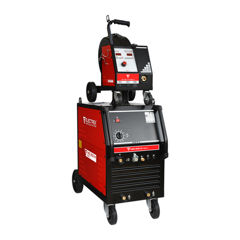
Electrex
Electrex Mig 306 M user guide

Tweco
Tweco PullMaster PMP3333545 Safety and operating instructions

