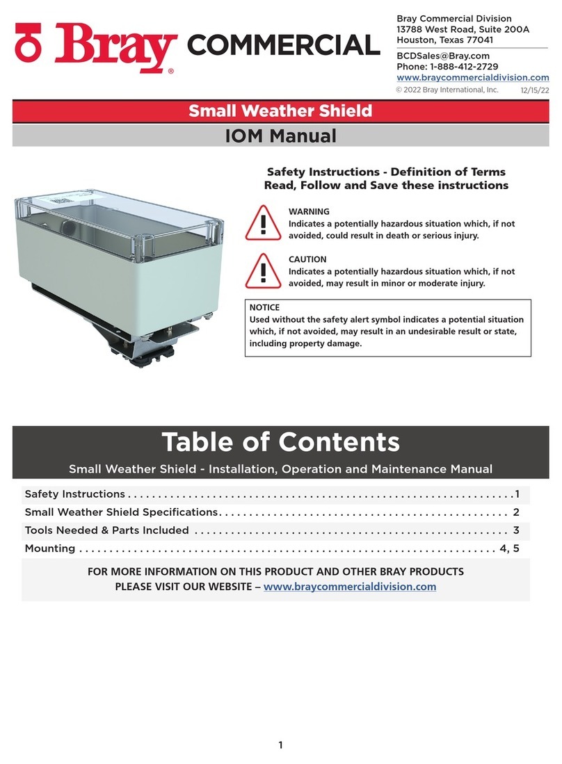
Bray WS-B-S180 User manual

1
12/15/22
© 2022 Bray International, Inc.
Bray Commercial Division
13788 West Road, Suite 200A
Houston, Texas 77041
BCDSales@Bray.com
Phone: 1-888-412-2729
www.braycommercialdivision.com
Large Weather Shield
IOM Manual
Safety Instructions . . . . . . . . . . . . . . . . . . . . . . . . . . . . . . . . . . . . . . . . . . . . . . . . . . . . . . . . . . . . . . . . 1
Large Weather Shield Specifications ............................................... 2
Install Instructions ............................................................... 3
FOR MORE INFORMATION ON THIS PRODUCT AND OTHER BRAY PRODUCTS
PLEASE VISIT OUR WEBSITE – www.braycommercialdivision.com
Table of Contents
Large Weather Shield - Installation, Operation and Maintenance Manual
Safety Instructions - Definition of Terms
Read, Follow and Save these instructions
WARNING
Indicates a potentially hazardous situation which, if not
avoided, could result in death or serious injury.
CAUTION
Indicates a potentially hazardous situation which, if not
avoided, may result in minor or moderate injury.
NOTICE
Used without the safety alert symbol indicates a potential situation
which, if not avoided, may result in an undesirable result or state,
including property damage.

2
Large Weather Shield - Installation, Operation & Maintenance Manual Continued
Description
The Bray Weather Shield is an industrial grade, convenient,
and cost-eective method of protecting actuators from the
harsh elements and washdowns, not just weather.
Features
• ABS - Injected with ultraviolet inhibitors
• Includes a gasket, anti-rotation bracket, anti-rotation
pin, and liquid-tight conduit connector.
• Base - Durable nylon blend that provides flexibility and durability
Benefits
• UV inhibitors prevent cover from becoming brittle
• Translucent Cover allows the actuator to be fully viewable
Dimensions
Specifications
Top Cover Polypropylene with added UV inhibitor.
Base Talc filled Polypropylene (20%), color black, color ratio 1%.
Enclosure Rating NEMA 4, IP55
IP55: Protected from limited dust ingress. Protected from low pressure water jets from any direction.
Temperature
For the Polypropylene used in your top and bottom parts, the recommended operating temperature
range is a minimum of -50˚F to a maximum 180˚F. The ASTM D648 thermal defection test rating is
160˚F, which is the temperature at which a test sample, under a load of 66 PSI, deflects by 0.25mm.
Dimensions (H x W x D) 8.04 x 14.50 x 7.17 in. (204.22 x 368.3 x 182.12 mm) - See Below
Weight 4.0 lb (1.8 kg)
Warranty 5 Years limited from time of shipment.
Anti-
Rotation
10-32 x 3/8" Screws
Cover
Screw through bracket
Side View
Gasket
Base Plate
14.50 (368.3)
6.90
(175.3)
7.17
(182.1)
7.17
(182.1)
1.14
(29)
Cover
Gasket
Base Plate
Tandem Bracket w/
Anti-Rotation Piece
Front View
3.75
FRONT
Liquid Tight Connector
Location:
1 for Single Mount
2 for Tandem Mount
Top View of Base Plate
10-32 x 3/8"
Screws
A = Mounting hole for D-140/210/280
AB
A B
C
B = Mounting hole for DS-180/DC310
& Tandem Actuator Bracket
C = Drive Pin Opening
Model Number Description - Actuators Covered
WS-B-S180 DS-180
WS-B-S180-T Tandem DS-180
WS-B-280 D-140, D-210 and D-280
WS-B-280-T Tandem D-140, D-210 and D-280
WS-B-310 DC-310
WS-B-310-T Tandem DC-310

3
Large Weather Shield - Installation, Operation & Maintenance Manual Continued
Preliminary Notes:
1. The weather shield comes fully assembled.
2. The cover is held in place with two 10-32 x 3/8" screws.
3. Inside the weather shield is a bag containing all the necessary hardware to assemble the weather shield.
a) Single Mounted Assemblies: 14) 10-32 x 3/8" screws, 1) Anti-Rotation Piece.
b) Tandem Mounted Assemblies: 16) 10-32 x 3/8" screws, 2) Anti-Rotation Pieces, 1) Tandem Bracket.
Installation Instructions:
1. Remove the 2 screws holding the cover in place. Lift cover o base plate and bracket.
2. Install anti-rotation piece in the appropriate hole to accommodate the actuator used on your valve
assembly. (Refer to diagram B) If tandem, then attach the tandem bracket to the base using two
provided 10-32 x 3/8" screws in the appropriate hole for the appropriate actuator.
(Refer to Diagram B for the appropriate mounting hole and diagram C for mounting.)
3. Drive the actuator on the valve assembly to zero volts.
4. Loosen nuts on u-bolt assembly, and lift actuator o of drive pin and valve assembly. If you have an old
style bracket that does not have the *holes (refer to diagram B) to accommodate the weather shield,
first bend down the anti-rotation piece so it is flat, then measure 3-3/4" from the center of the drive pin
to the center mark between the holes that will be drilled. From that center mark measure 1/2" to the
center of each 1/4" diameter hole. (Template included with the instructions.)
5. Slide slot in the back of the actuator into the groove of the anti-rotation piece. If the anti-rotation piece
was installed in the correct hole, the drive pin hole in the base and the drive pin hole in the actuator and
u-bolt assembly should line up. If not repeat step 2.
6. With the actuator in place slide actuator and base of weather shield over drive pin and on valve
assembly. If tandem, slide half way down on pin, slide second actuator on the tandem bracket anti-
rotation piece, and then down on the drive pin and valve assembly. Secure the base to the bracket using
two provided 10-32 x 3/8" screws. (See diagram C.)
7. Actuator should be at 0 Volts. Re-tighten u-bolt assembly. If the valve assembly is single mount proceed
to step 9. If the valve assembly is tandem mounted go to next step.
8. Be sure second actuator is at 0 Volts. Lift the front of the actuator so that it is parallel to the bottom
actuator and tighten U-bolt assembly.
9. Feed cable from the Actuator through the liquid tight connector.
10.Place gasket on cover. Hold gasket in place by inserting remaining 12) 10-32 x 3/8" screws through cover
and gasket. Place cover and gasket on base plate and tighten the 12) 10-32 x 3/8" screws that hold it in
place. The Weather shield will be fully assembled at this point.
This manual suits for next models
5
Other Bray Enclosure manuals
