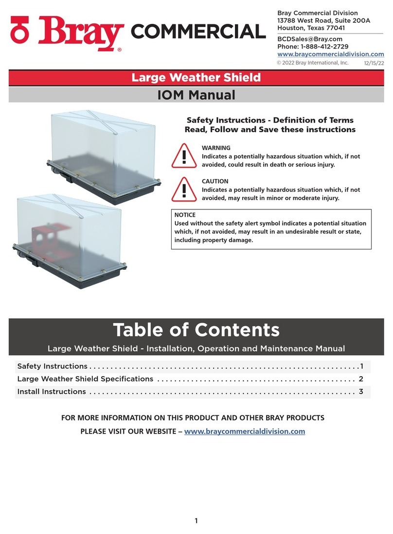
Bray Small Weather Shield User manual

1
12/15/22
© 2022 Bray International, Inc.
Bray Commercial Division
13788 West Road, Suite 200A
Houston, Texas 77041
BCDSales@Bray.com
Phone: 1-888-412-2729
www.braycommercialdivision.com
Small Weather Shield
IOM Manual
Safety Instructions . . . . . . . . . . . . . . . . . . . . . . . . . . . . . . . . . . . . . . . . . . . . . . . . . . . . . . . . . . . . . . . . 1
Small Weather Shield Specifications................................................ 2
Tools Needed & Parts Included .................................................... 3
Mounting .....................................................................4, 5
FOR MORE INFORMATION ON THIS PRODUCT AND OTHER BRAY PRODUCTS
PLEASE VISIT OUR WEBSITE – www.braycommercialdivision.com
Table of Contents
Small Weather Shield - Installation, Operation and Maintenance Manual
Safety Instructions - Definition of Terms
Read, Follow and Save these instructions
WARNING
Indicates a potentially hazardous situation which, if not
avoided, could result in death or serious injury.
CAUTION
Indicates a potentially hazardous situation which, if not
avoided, may result in minor or moderate injury.
NOTICE
Used without the safety alert symbol indicates a potential situation
which, if not avoided, may result in an undesirable result or state,
including property damage.

2
Small Weather Shield - Installation, Operation & Maintenance Manual Continued
For ST2 Ball Valves with VA Series Actuators
Description
The Bray Small Weather Shield is an industrial grade, convenient,
and cost-eective method of protecting actuators from the harsh
elements and washdowns, not just weather.
Features
• Enclosure - constructed of impact-grade plastic that provides
excellent impact resistance.
• Fully Enclosed Design - Protects the electric actuator from
corrosion, rain, freezing rain, sleet, and snow.
• Strain Relief Conduit Fittings - Protect the electric actuator from
damage by preventing tension on the electrical connection.
Benefits
• UV inhibitors prevent cover from becoming brittle or damaged by the sun
or other environmental elements.
• Translucent Cover provides an unobstructed view of the electric actuator
without having to disassemble the enclosure.
Dimensions
Specifications
Top Cover Transparent UV resistant polycarbonate plastic
Enclosure Seal Nitrile
Body UV resistant polycarbonate plastic
Cover Gasket Polyurethane
Electrical
Connections
Strain relief conduit fittings with 1/2 in. (13 mm)
National Pipe Straight Mechanical (NPSM) exit
Ambient
Temp. Limits -40 to 176°F (-40 to 80°C)
Dimensions See Below
Protection Rating NEMA 4X, IP66
Weight 4.2 lb (1.9 kg)
Warranty 5 Years limited from time of shipment
Model Number Description - Actuators Covered
M9000-342 ST2 Direct Mount
(VA Series) Actuators
B
D
C
E
A
Dimensions - Small Weather Shield - in. (mm)
in. mm A B C D E
- ()
-
()
-
()
-
()
-
()
- ()
- ()
()
- ()
- ()

3
Small Weather Shield - Installation, Operation & Maintenance Manual Continued
Special Tools Needed:
• 8 mm (5/16 in.) open-end wrench
• 6 mm (1/4 in.) flat-blade screwdriver
• No. 1 Phillips screwdriver
• No. 2 Phillips screwdriver
21 mm and 22 mm open end wrench
(or two adjustable wrenches)
Parts Included:
Table 1: Parts Included in Small Weather Shield Enclosure Kits
Callout Quantity Description
1A 1 Base, enclosure
1B 1 Clear enclosure cover
1C 4 Screw, cover (factory-installed)
5 1 Bearing, seal carrier (factory-installed)
6 1 Seal, lip (factory-installed)
7 1 O-Ring, RoHS (factory-installed)
8 1 Plate, inner (factory-installed)
9 4 Screw, button head Torx, RoHS (factory-installed)
1024Screw, M3 x 0.5 x 8 mm long, Phillips, oval countersink
1124Washer, flat, M4, plain steel, 4.3 mm ID x 9.0 mm OD x 0.8 mm
1221Bracket, Anti-rotation, weather shield
13 1 Bracket, mounting
14 4 Screw, machine, #6-32 x 1/2 in. long, cross-recessed pan head, RoHS
15 4 Nut, #6-32 hex, flanged, serrated tooth, RoHS
16 1 Bracket, valve
17 1 Bearing, plastic, flanged, split, 20 mm ID, RoHS (factory-installed)
18 1 Shaft, valve
19 3 Screw, tapping, hex washer head, type F, RoHS
Figure 2: Parts Included (See Table 1)
20 1 Thermal barrier
23 2 Gland, cable, PG11 to 1/2 in. NPSL
24 1Cap plug, PG11 with O-Ring, RoHS
25 2Nut, hex, single chamfer, PG11
26 1Label (factory-installed)
3021Screw, tapping, hex washer head, type SW, RoHS
3121Shaft, valve, 1 in. diameter
3221Screw, M4 x 0.7 x 60 mm long, Torx.slotted pan head
1. We recommend using a 1/2 in. liquid-tight conduit and 1/2 in. National Pipe Thread (NPT) liquid-tight fittings (purchased
locally) to terminate the control wiring to the weather shield enclosure strain relief conduit fittings.

4
Small Weather Shield - Installation, Operation & Maintenance Manual Continued
Mounting:
Mount the valve in a location with sufficient clearance
to remove the weather shield cover and actuator.
Before installing the electric actuator, use an adjustable
wrench to manually rotate the valve stem several
times. Rotating the valve stem breaks the torque that
may have built up during long-term storage.
To mount the Small Weather Shield Kits:
1. Position the valve ball and stem to the preferred
spring return position. To mount the actuator to
Spring Return Port A (Coil) Open, turn the valve
stem to the position in Figure 4. To mount the
actuator to Spring Return Port A (Coil) Closed, turn
the valve stem to the position in Figure 5.
Note:Position the valve ball stem to the position in
Figure 4.
2. Place the Teflon® thermal barrier on the ball valve
actuator mounting flange by inserting the alignment
rib on the bottom of the thermal barrier into the
recess on mounting flange (Figure 6).
3. Install the valve adapter bracket over the thermal
barrier and attach the valve adapter bracket to the
valve using the four M6 screws and flanged nuts
(Figure 7). Tighten screws to a recommended
torque of 35 to 44 lb·in. (4.0 to 5.0 N·m).
Note:Before you fully tighten the screws, temporarily
install the valve shaft through the adapter bracket and
engage the valve stem. This action ensures proper
alignment with the valve stem and adapter bracket.
Figure 4: Positioning the Valve Stem -
Spring Return Port A (Coil) Open
3 Way2 Way
2 Way 3 Way
Figure 5: Positioning the Valve Stem -
Spring Return Port A (Coil) Closed
Figure 6: Mount the
Thermal Barrier
Figure 7: Install Valve Bracket

5
Small Weather Shield - Installation, Operation & Maintenance Manual Continued
Continued:
4. Secure the weather shield enclosure mounting
bracket (Figure 8) to the valve adapter bracket by
using the raised alignment aids (Figure 9) for
positioning and the three 12-24 x 1/2 in.
self-tapping screws. Tighten the screws to a
recommended torque of 31 to 40 lb·in.
(3.5 to 4.5 N·m).
5. Install the strain relief conduit adapters in the
weather shield base. Use one adapter for actuators
without switches or two adapters for actuators with
switches. If you only use one adapter, seal the
remaining hole with the cap plug and nut. Tighten
the strain relief and cap plug nuts to a torque of 27
to 35 lb·in (3 to 4 N·m).
6. Align marks on top of the valve stem extension
shaft with marks on the valve stem and install the
weather shield base and seal assembly on the
weather shield enclosure mounting bracket.
Secure tightly using the four 6-32 x 1/2 in. screws
and nuts. Tighten the screws to a recommended
torque of 9 to 12 lb·in. (1 to 1.4 N·m).
7. Set up the valve actuator linkage according to the
instructions supplied with the actuator.
8. Install the valve actuator into the weather shield
feeding the electrical cables through the strain
relief conduit adapters and position the actuator on
to the internal bracket.
9.
Tighten the screw in the center of the fixed pointer
to valve stem extension to a torque of 10 to
12 lb·in. (1.1 to 1.4 N·m). Tighten the conduit fitting
to a torque of 25 to 30 lb·in. (2.8 to 3.4 N·m) to
secure the electrical cord in place.
10. Install the weather shield cover and gasket
assembly using the four cover screws supplied
with the kit. Tighten the screws to a recommended
torque of 9 to 12 lb·in (1.0 to 1.4 N·m).
Repair Information
If the Small Weather Weather Shield
Enclosure fails to operate within its specifications,
replace the unit. For a replacement weather shield,
contact the nearest Johnson Controls representative.
Figure 8: Weather Shield on
Mounting Bracket
Figure 9: Raised Alignment Aids
Alignment
Aids
?g:alignment
Figure 10: Actuator within Small Weather
Shield Kit
Table of contents
Other Bray Enclosure manuals
