Breezair MobileMAX III User manual

INSTRUCTION
MANUAL
FOR MODELS
MobileMAX II & MobileMAX III
High Performance Mobile
Evaporative Coolers
1. Safety Instructions
2. Assembly
3. Features
4. Operation
5. Maintenance
6. Replacement Parts
7. Troubleshooting
TM
SEELEY
|NTERNATnONAL
(Am e_icas)
Read this manual before
operating the product

Section 1 - SAFETY
WARNING: The warnings and
safety instructions in this
manual MUST be followed to
reduce the risk of fire, electric
shock, or injury, and to provide
reasonable safety and efficiency
in using this cooler.
The operator is responsible for
following the warnings and
instructions in this manual and
on the cooler. Read the entire
manual before using the cooler.
Restrict the use of this cooler to
persons who read, understand,
and follow the warnings and
instructions in this manual and
on the cooler. Never allow
children to operate this cooler.
Failure to observe these
warnings and instructions will
void manufacturer's warranties
and discharge manufacturer of
all liability.
CA UTION:
Always disconnect the cooler
from the power supply before
commencing maintenance
procedures.
During maintenance procedures
: NEVER use a naked flame for
any inspection or cleaning
purposes as a fire could be
caused as a result of a flame
coming into contact with the
cooler's structure.
Avoid Dangerous Situations:
Protect the cooler from all
sources of ignitions because
polymers and filter pads will
burn.
NEVER use a water hose to
squirt the cooler's interior for
cleaning as residual water
could damage electrical
components and create the risk
of fire and/or electric shock to
the user after re-assembly
Installation, Repair and
Operation
•All installation and repair work
must conform to local electrical,
water supply, environmental
codes, rules and regulations, and
applicable national standards.
Ensure compliance with local
regulations.
•Installation and repair work must
be done by a licensed and
qualified electrician and/or a
qualified experienced heating,
ventilation, air conditioning
technician. All installation and
repairs must be made with factory
authorized parts only.
• Use only approved replacement
parts for all electrical components.
If in doubt about what replacement
parts to use, do not guess,
contact Convair Cooler
Corporation.
Use of wrong replacement parts
creates risk of severe electric
shock and fire, which may result
in serious property damage,
personal injury or death.
•Use only thermal overload
protected pumps! Water pumps
may seize up and overheat,
creating a fire risk. Pumps that
have thermal overload protection
are designed to shut off electricity
to the pump if the pump seizes and
overheats.
•Use only water pumps with
three pronged grounded plugs!
Use of ungrounded plugs creates
risk of severe electrical shock and
fire. Never use pumps with bare
ended wires.
Water pump must be replaced
with authorized pump models
(See Appendix 1).
•Use only evaporative cooler
motors with thermal overload
protection! Evaporative cooler
motors may seize up and overheat,
creating a fire risk. Motors with
thermal overload protection are
designed to shut off the motor if
motor seizes and
See Appendix 1 for authorised
replacement fan motors.
The following safety requirements
should be met to ensure safe and
reliable operation of your new
cooler:
•This cooler is not flame
retardant. Polymers will burn if
ignited, protect cooler from all
sources of ignition (flame/
electrical shorts).
•Disconnect electrical power
before servicing, cleaning or
performing maintenance on the
cooler. Turn OFF the isolating
switch inside the cooler before
installing, servicing, cleaning or
performing maintenance on the
cooler.
• Use only a voltage supply as
shown on the name plate of the
motor.
• Before servicing the equipment
make certain children, people and
animals are a minimum of 30ft.
(lOm) away from the work area.
•Dress safely !,Jewellery, loose
clothing, clothing with loosely
hanging straps, ties, tassels, etc.,
can be caught in moving parts.
•Keep loose hair, fingers and all
other parts of the body away from
openings and moving parts.
• Check the cooler before
operation. Look for worn, loose,
missing or damaged parts. Do not
use the cooler until it is in proper
working order.

Section 1 - SAFETY & Section 2 -ASSEMBLY
•Avoid dangerous situations. Do
not use in the presence of
flammable fiquids or gases to
avoid creating a fire or explosion
and/or causing damage to this
cooler.
•Avoid any body contact with any
grounded conductor, such as a
metal pipe to avoid possibility of
electric shock.
• Ground Fault Circuit Interrupter
(GFCI) protection should be
provided on the circuit used for
this cooler. Receptacles are
available having butt-in GFCI
protection and may be used for
this measure of safety.
•Never drain the air cooler onto
the floor. Connect a hose from the
drain fitting to a drain or gutter.
Water residue could stain or cause
you to slip.
•Always use the correct tools.
WARNING:
The plastic
covering this
cooler
can be a safety
hazard
Please dispose
of thoughtfully.
This column is intentionally left
blank Removal & Replacement of
Pad Frames
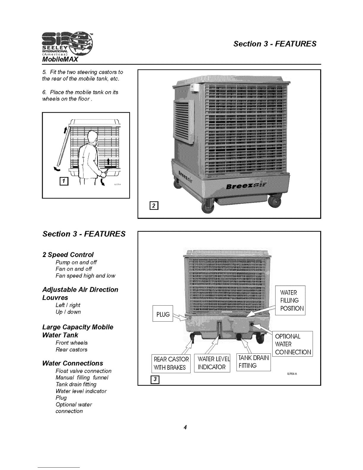
Each pad frame is clipped into the
cooler and is removable by use of
a medium screwdriver inserted into
slots at the base of the sides and
levered downwards (see Fig. 1
,page 4). The side will then slide
down and out of the cooler cabinet.
To replace the pad frame, ensure
that it is the right way up, i.e. with
the water channel upwards.
Then fit the side in and up at the
top and then in at the bottom. Use
the screwdriver again, and insert it
between the bottom of the side and
the pan/tank wall at the center, and
lever upwards, until the side locks
into place.
Fitting the Wheels
Two wheels and two castors (with
brakes) are supplied with each
MobileMAX. They are packed
inside the cooler.
1. Remove the rear pad frame.
2. Remove the package of
castors, wheels and fasteners from
inside the cooler.
3. Carefully roll the cooler onto
one side, onto a piece of carpet or
cardboard so as not to damage the
cooler.
Warning :
Check to be sure that the voltage
rating of the cooler components is
compatabile with your electrical
voltage system
4. Fit the two fixed wheels to the
front of the mobile tank using the
screws provided (screw type). It is
not necessary to drill holes for
these screws. DO NOT
OVERTIGHTEN.
MobileMAX
5. Fit the two steenng casto_ to
the rear of the mobile tank, etc.
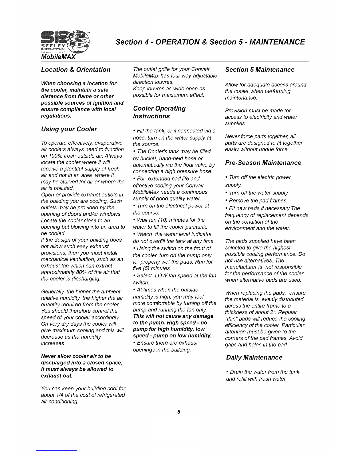
6. Place the mobile tank on its
wheels on the floor.
Section 3-
2 Speed Control
Pump on and off
Fan on and off
Fan speed high and low
Adjustable Air Direction
Louvres
Left / fight
Up/ down
Large Capacity Mobile
Water Tank
Front wheels
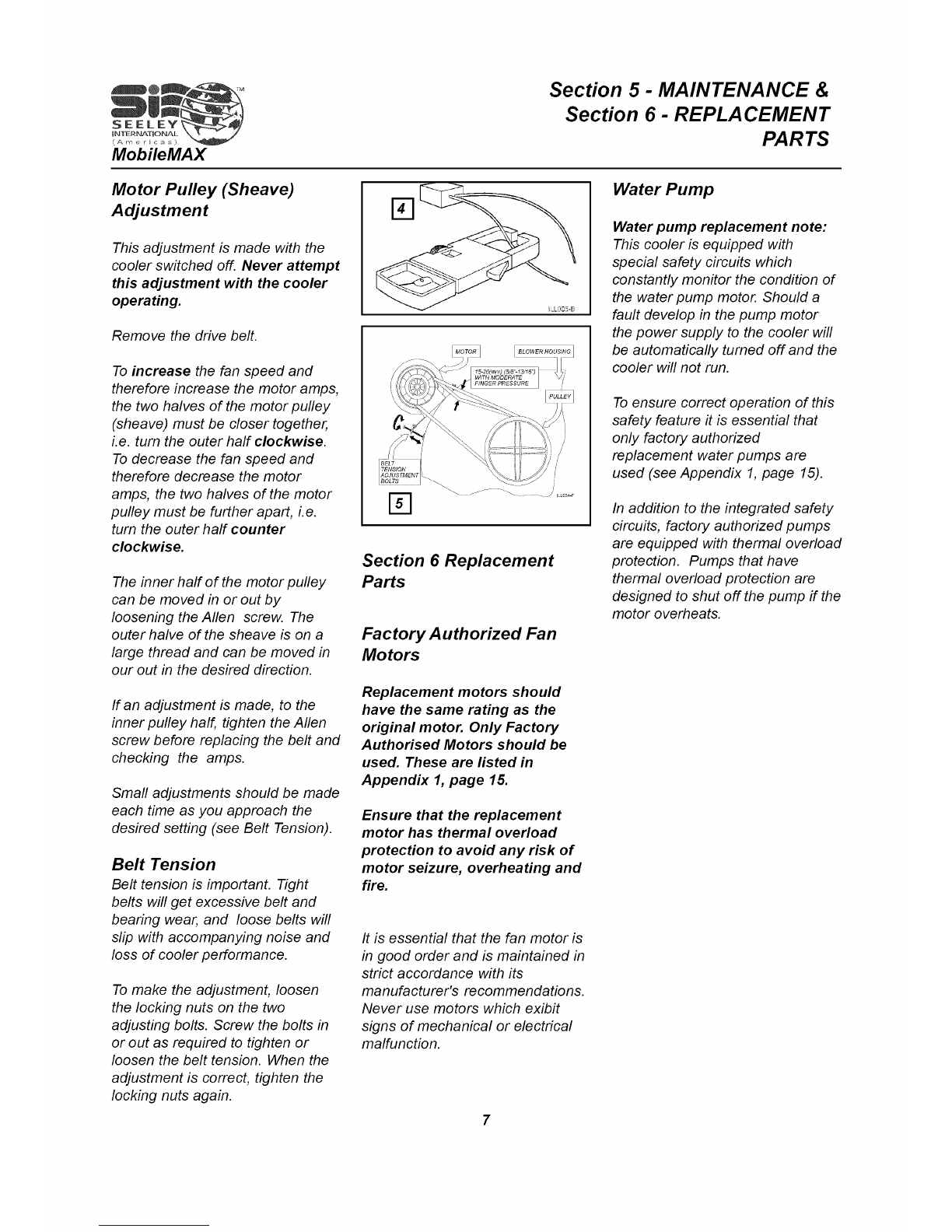
Water Connections
Float valve connection
Manual filling funnel
Tank drain fitting
Water level indicator
Plug
Optional water
PLUG
REARCASTOR
WITHBRAKES WATERLEVEq
INDICATOR|
TANKDRAIN
FITTING
WATER
FILLI[IG
POSITION
OPTI©NAL
WATER
CO Nr,,IECTIOI',,I
I[L'?04-A
4
Section 4 - OPERATION & Section 5 - MAINTENANCE
Location & Orientation
When choosing a location for
the cooler, maintain asafe
distance from flame or other
possible sources of ignition and
ensure compliance with local
regulations.
Using your Cooler
To operate effectively, evaporative
air coolers always need to function
on 100% fresh outside air. Always
locate the cooler where it will
receive a plentiful supply of fresh
air and not in an area where it
may be starved for air or where the
air is polluted.
Open or provide exhaust outlets in
the building you are cooling. Such
outlets may be provided by the
opening of doors and/or windows.
Locate the cooler close to an
opening but blowing into an area to
be cooled.
If the design of your building does
not allow such easy exhaust
provisions, then you must install
mechanical ventilation, such as an
exhaust fan which can extract
approximately 80% of the air that
the cooler is discharging.
Generally, the higher the ambient
relative humidity, the higher the air
quantity required from the cooler.
You should therefore control the
speed of your cooler accordingly,
On very dry days the cooler will
give maximum cooling and this will
decrease as the humidity
increases.
Never allow cooler air to be
discharged into a closed space,
# must always be allowed to
exhaust out.
You can keep your building cool for
about 1/4 of the cost of refrigerated
air conditioning.
The outlet grille for your Convair
MobileMax has four way adjustable
direction Iouvres.
Keep Iouvres as wide open as
possible for maxiumum effect.
Cooler Operating
Instructions
•Fill the tank, or if connected via a
hose, turn on the water supply at
the source.
•The Cooler's tank may be filled
by bucket, hand-held hose or
automatically via the float valve by
connecting a high pressure hose.
• For extended pad life and
effective cooling your Convair
MobileMax needs a continuous
supply of good quality water.
• Turn on the electrical power at
the source.
• Wait ten (10) minutes for the
water to fill the cooler pan/tank.
• Watch the water level indicator,
do not overfill the tank at any time.
• Using the switch on the front of
the cooler, turn on the pump only
to properly wet the pads. Run for
five (5) minutes.
• Select LOWfan speed at the fan
switch.
• At times when the outside
humidity is high, you may feel
more comfortable by turning off the
pump and running the fan only,
This will not cause any damage
to the pump. High speed - no
pump for high humidity, low
speed - pump on low humidity.
• Ensure there are exhaust
openings in the building.
Section 5 Maintenance
Allow for adequate access around
the cooler when performing
maintenance.
Provision must be made for
access to electricity and water
supplies.
Never force parts together, all
parts are designed to fit together
easily without undue force.
Pre-Season Maintenance
• Turn off the electric power
supply.
• Tum off the water supply.
• Remove the pad frames.
• Fit new pads if necessary. The
frequency of replacement depends
on the condition of the
environment and the water.
The pads supplied have been
selected to give the highest
possible cooling performance. Do
not use alternatives. The
manufacturer is not responsible
for the performance of the cooler
when alternative pads are used.
When replacing the pads, ensure
the material is evenly distributed
across the entire frame to a
thickness of about 2". Regular
"thin" pads will reduce the cooling
efficiency of the cooler. Particular
attention must be given to the
comers of the pad frames. Avoid
gaps and holes in the pad.
Daily Maintenance
• Drain the water from the tank
and refill with fresh water

Section 5 - MAINTENANCE
•If the pads are reused they can
be easily cleaned by squirting them
with a hose. Do not use excess
pressure. This may create holes in
the pad.
• Remove the pad from the pad
frame, clean, and evenly
redistribute the wood wool over the
pad. Re-assemble the pad frame
• Inspect the pump and check that
it will freely rotate by hand. If it is
jammed with salt build-up, then
remove it and clean it thoroughly.
After cleaning the pump replace it
into the cooler, making sure that it
is securely in place.
• Check belt tension and adjust if
necessary.
• Lubricate motor bearings (if oiler
fitted) -only lightly.
• Replace the pad frames.
• Refill the tank.
• Restore electrical power supply
and follow Operating Instructions.
In-Season Maintenance
DAILY"
• Drain the water from the tank and
refill with fresh water,
MONTHLY
• Tum off the electrical power
supply.
• Remove the pad frames.
• Inspect the pads and clean or
replace the material as required
(see Pre-Season Maintenance).
•Check the water level and adjust
the float if necessary.
•Check the pump operation.
• Clean the tank.
• Replace the pad frames.
• Restore electrical power supply
and follow Operating Instructions.
• Check that the wood-wool is
evenly distributed, and that there is
no gaps.
End Season Maintenance
• Tum off electrical power supply.
• Tum off water supply if
connected.
• Remove the pad frames. Hose
them down carefully, do not use
excess pressure as this may
create holes in the pad material
(see Pre-Season Maintenance).
• Remove and clean the special
patented water "spreader plates"
located under the top panel of the
cooler, above each pad frame (see
Fig. 12, page 10, item 43). When
replacing them, ensure the
spreader is correctly locating in the
notches under the top panel,
halfway along the side.
It should not be necessary to
remove the spreader from the
hoses, simply clean them at the
cooler.
• Drain all the water from the
cooler.
• Clean the bottom pan/tank
thoroughly.
• Disconnect the water supply line.
Leave disconnected until next
season to prevent freezing and
splitting.
• Replace the pad frames.
• Cover the cooler for the winter or
store indoors.
Motor Power (Amps)
Your cooler is fitted with an
adjustable motor pulley (sheave) to
enable the cooler to provide
maximum cooling. The adjustment
of the pulley must be done by a
trained, licensed technician using a
clip on ammeter Maximum amps
should not exceed the motor
nameplate amps.
Install all pad frames, except the
one on the motor side.
Set the cooler running at highest
speed for approximately ten (10)
minutes or until the motor has
reached its normal operating
temperature. Motor load must be
checked without the water pump
running.
Locate the motor current test wire
in the terminal box. Measure the
motor current using a clip-on
ammeter (see Fig. 4, page 7). This
should be done by a trained,
licensed technician. Check the
measured amps against the
motor's nameplate rating.
If the measured amps are less
than the nameplate amps the
adjustable pulley may be altered to
increase the fan speed, thereby
delivering the full cooler capability
to your installation. The measured
amps should be equal or very
close to the motor's nameplate
amps (see heading Pulley
[Sheave] Adjustment below).
If the measured amps are
greater than the nameplate
amps the fan must be slowed by
adjusting the same pulley in the
opposite direction. Failure to do
this will overheat the motor
which may result in a fire.
Replace all covers when
adjustments are complete.
Section 5 - MAINTENANCE &
Section 6 - REPLA CEMENT
PARTS
Motor Pulley (Sheave)
Adjustment
This adjustment is made with the
cooler switched off. Never attempt
this adjustment with the cooler
operating.
Remove the drive belt.
To increase the fan speed and
therefore increase the motor amps,
the two halves of the motor pulley
(sheave) must be closer together,
i.e. turn the outer half clockwise.
To decrease the fan speed and
therefore decrease the motor
amp& the two halves of the motor
pulley must be further apart, i.e.
turn the outer half counter
clockwise.
The inner half of the motor pulley
can be moved in or out by
loosening the Allen screw. The
outer halve of the sheave is on a
large thread and can be moved in
our out in the desired direction.
If an adjustment is made, to the
inner pulley half, tighten the Allen
screw before replacing the belt and
checking the amps.
Small adjustments should be made
each time as you approach the
desired setting (see Belt Tension).
Belt Tension
Belt tension is important. Tight
belts will get excessive belt and
bearing wear, and loose belts will
slip with accompanying noise and
loss of cooler performance.
To make the adjustment, loosen
the locking nuts on the two
adjusting bolts. Screw the bolts in
or out as required to tighten or
loosen the belt tension. When the
adjustment is correct, tighten the
locking nuts again.
Section 6 Replacement
Parts
Factory Authorized Fan
Motors
Replacement motors should
have the same rating as the
original motor. Only Factory
Authorised Motors should be
used. These are listed in
Appendix 1, page 15.
Ensure that the replacement
motor has thermal overload
protection to avoid any risk of
motor seizure, overheating and
fire.
It is essential that the fan motor is
in good order and is maintained in
strict accordance with its
manufacturer's recommendations.
Never use motors which exibit
signs of mechanical or electrical
malfunction.
Water Pump
Water pump replacement note:
This cooler is equipped with
special safety circuits which
constantly monitor the condition of
the water pump motor. Should a
fault develop in the pump motor
the power supply to the cooler will
be automatically turned off and the
cooler will not run.
To ensure correct operation of this
safety feature it is essential that
only factory authorized
replacement water pumps are
used (see Appendix 1,page 15).
In addition to the integrated safety
circuits, factory authorized pumps
are equipped with thermal overload
protection. Pumps that have
thermal overload protection are
designed to shut off the pump if the
motor overheats.

Section 6 - REPLACEMENT PARTS
Motor Connection (non
Seeley motors)
The new cooler is supplied with a
special motor cord. If replacing
motor, remove cord from old motor
and connect to new motor as
follows:
green/green-yellow- to motor
grounding screw
black -high speed
red / brown -low speed
white / blue -common / neutral.
WARNING:
Take care to ensure correct
connection of fan motor.
Incorrect connection can create
a risk of electric shock or fire.
Replace the electrical connection
coven Place the motor into the
cradle so that the motor shaft
protrudes at the same side as the
fan pulley; fit the clamps (with the
heads of the screws facing you)
and tighten securely.
When placing the motor in the
cradle, rotate it so that the vent
holes are positioned in accordance
with the motor manufacturer's
recommendations. Ensure the cord
is not stressed in any way.
Take the adjustable aluminium
motor pulley and slide it onto the
motor shaft with the adjustable side
of the pulley towards the end of the
shaft, making sure that the Allen
screw will tighten down onto the
"flat" on the motor shaft.
Now align the motor and fan
pulleys. It is essential that the
pulleys are correctly aligned. Poor
alignment will cause excessive
belt, pulley and bearing wear.
The correct alignment of the
pulleys and the tightening of the
motor pulley (sheave) onto the
"flat" of the shaft is most important
to ensure successful transmission
of the motor power (torque) to the
fan and prevent slipping.
Electrical Installation
Wiring must comply with local
codes and regulations and should
only be carried out by a trained,
licensed technician.
Wiring must be rated to carry at
least the nameplate current
(amperes) of the fan motor and
must be protected by a suitable
fuse or circuit breaker.
The main junction box is factory
sealed, do not attempt to open
this junction box, there are no
field terminations or serviceable
parts within.
O
WASHERS
UNDERNEATH
BOLTHEAD
BELT
TENSION
ADJUSTING
NUTS
BRACKET
MOTOR
HOUSING
BOOT
MOTOR
MOUNTING
PLATE
SCROLL NO WASHERS ILL016
Ensure all electrical
connections are tight. Loose
connections cause overheating
which can result in machine
malfunction or fires.
The main junction box includes
plug receptacles for the fire
protection system, fan motor and
water pump (see Fig. 14, page 15).
Note: The cord to the fire
protection system must be
plugged in before the cooler will
operate. Any attempt to tamper
with, or disable the fire
protection system will render
the cooler inoperative.
NOTE: SMALL BLOWER HOUSING
TED
WARNING:
High voltage inside. Only use
the screws supplied to replace
the rid covering
external terminals.
Section 6 - REPLACEMENT PARTS
Fan Bearing Replacement
Sometimes a fan shaft bearing will
fail and must be replaced in the
field. Before removal of the
bearings, ensure you have a
Bearing Kit (Part No. 800523).
The following procedure should be
ahered to (see Fig. 27, and parts
list):
To Remove Bearings
•Ensure electric power is
disconnected.
• Remove belt.
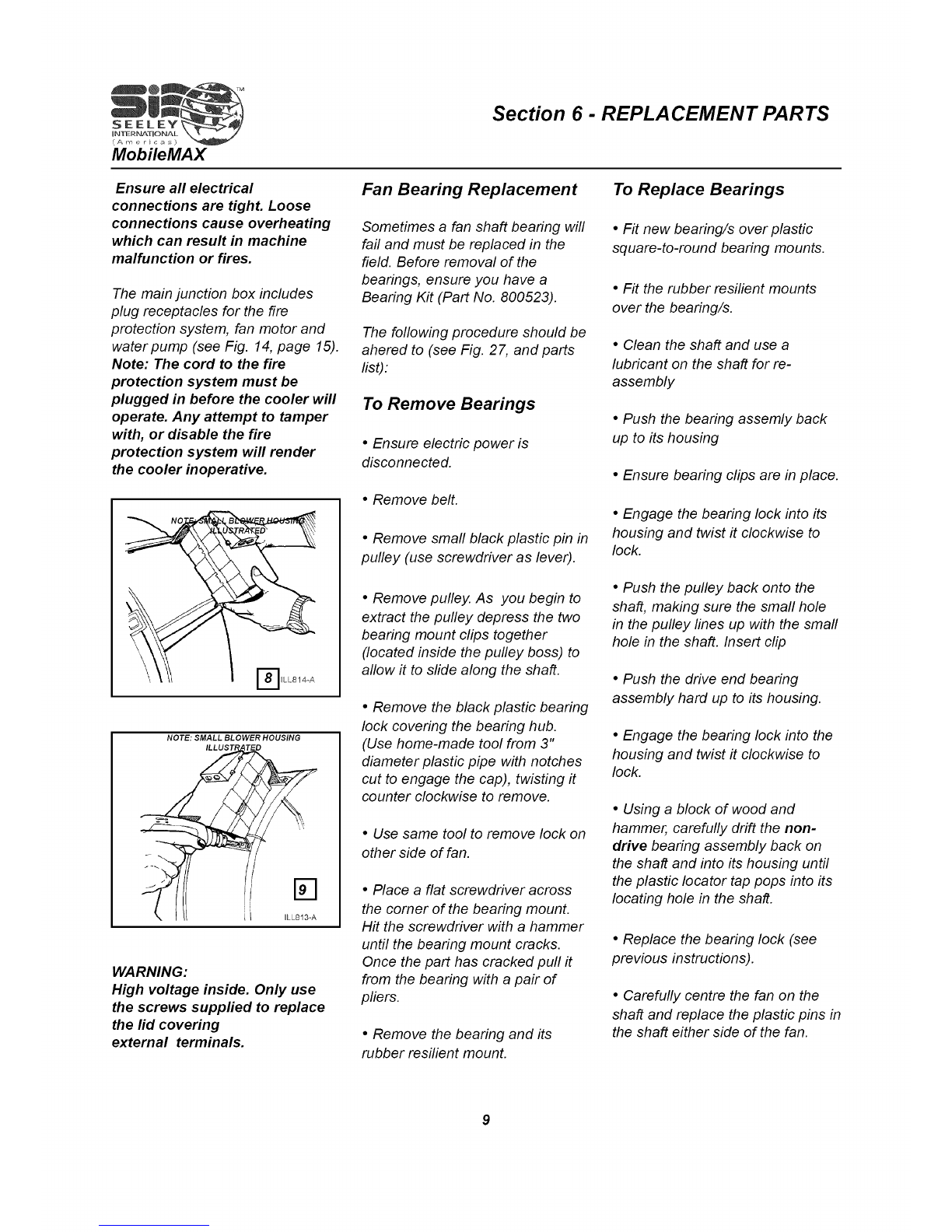
• Remove small black plastic pin in
pulley (use screwdriver as lever).
•Remove pulley. As you begin to
extract the pulley depress the two
bearing mount clips together
(located inside the pulley boss) to
allow it to slide along the shaft.
•Remove the black plastic bearing
lock covering the bearing hub.
(Use home-made tool from 3"
diameter plastic pipe with notches
cut to engage the cap), twisting it
counter clockwise to remove.
•Use same tool to remove lock on
other side of fan.
• Place a flat screwdriver across
the comer of the bearing mount.
Hit the screwdriver with a hammer
until the bearing mount cracks.
Once the part has cracked pull it
from the bearing with a pair of
pliers.
•Remove the bearing and its
rubber resilient mount.
To Replace Bearings
•Fit new bearing/s over plastic
square-to-round bearing mounts.
•Fit the rubber resilient mounts
over the bearing/s.
•Clean the shaft and use a
lubricant on the shaft for re-
assembly
•Push the bearing assemly back
up to its housing
•Ensure bearing clips are in place.
•Engage the bearing lock into its
housing and twist it clockwise to
lock.
•Push the pulley back onto the
shaft, making sure the small hole
in the pulley lines up with the small
hole in the shaft. Insert clip
•Push the drive end bearing
assembly hard up to its housing.
•Engage the bearing lock into the
housing and twist it clockwise to
lock.
•Using a block of wood and
hammer, carefully drift the non-
drive bearing assembly back on
the shaft and into its housing until
the plastic Iocator tap pops into its
locating hole in the shaft.
•Replace the bearing lock (see
previous instructions).
• Carefully centre the fan on the
shaft and replace the plastic pins in
the shaft either side of the fan.

Exploded Diagrams
Bearing
LOOI¢ _t01JNT
vS
INgO PtSLLtTY
Section 6- REPLACEMENT PARTS
Drive S
@
Unit
14
ILL835-B
/
/
,/
i
@10

MobileMAX
ITEM
1
2
3
4
5
6
7
8
9
10
13
15
17
18
19
20
21
22
23
24
25
27
28
29
DESCRIPTION
PAN/TANK
LID
PANEL FRONT
PAD FRAME
PAD ASSEMBLY
WIRE ASSEMBLY
POST CORNER
SCROLL L/H (MOTOR)
SCROLL R/H
PLATE CUTOFF
BAFFLE
SEALING TAPE
PLATE MOTOR MOUNT
BOLT CUP HEAD
WASHER MIO x 21 x 1.6ZP
NUT WHIZ M8ZN
BRA CKE T MOTOR MOUNT
ADJUSTING
BOLT
BOOT
RIVETS & WASHERS (FOR PLATE
MOTOR MOUNT NOT ILLUSTRATED
PLUG HOLE TRANSITION
PUMP MOTOR
MOTOR
JUNC TION/TERMINAL BOX
QTY
1
1
1
3
3
3
4
1
1
1
2
1
4
2
8
2
2
2
1
1
1
Section 6-REPLACEMENT PARTS
ITEM
3O
31
32
33
34
35
36
37
38
39
4O
42
43
44
45
46
47
48
49
5O
51
52
53
54
55
56
DESCRIPTION
FAN CENTRIFUGAL
SHAFT (FAN)
BEARING
MOUNT RESILIENT BEARING
MOUNT BEARING (NON DRIVE END
MOUNT BEARING (DRIVE END)
LOCK BEARING (NON DRIVE END)
LOCK BEARING (DRIVE END)
PULLEY FAN (205 or 225)
PULLEY MO TOR ADJUS TABLE
PIN BLACK PLASTIC
V-BELT
SPREADER
4 WAY DISTRIBUTOR
PVC TUBE 3/4" (ID)
PVC TUBE 1/2" (ID)
FIRE DETECTOR (If used)
BOTTLE (RESERVOIR)
SPRINKLER AND TEE-PIECE ASSY
FLOAT VALVE ASSEMBLY
NUT
GRILLE
GRILLE MOUNT
CASTOR (LOCKING)
SCREW M8 x 75 (NOT ILLUSTRATEE
CASTOR WHEELS
QTY
1
1
2
2
1
1
1
1
1
1
3
1
3
1
1
1
1
1
1
1
1
2
11
Section 7- TROUBLESHOOTING
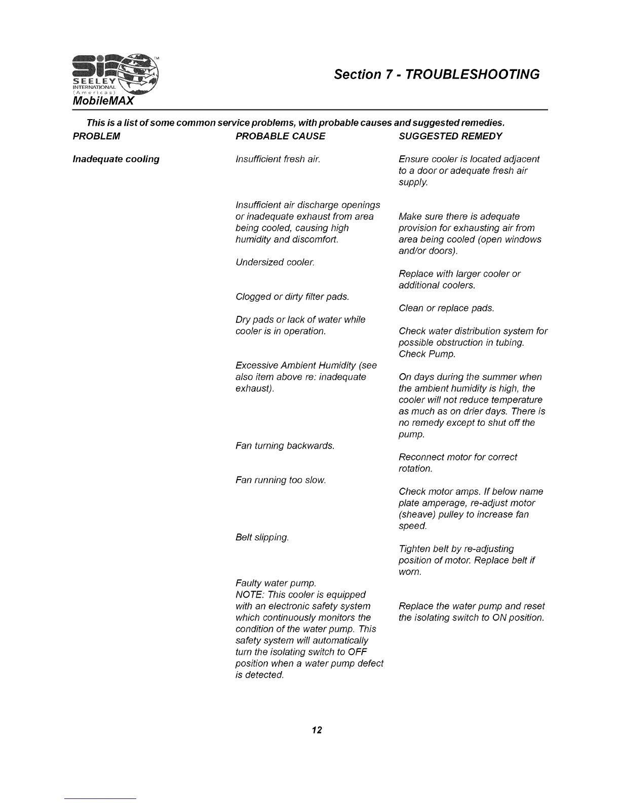
This is a list of some common service problems, with probable causes and suggested remedies.
PROBLEM PROBABLE CAUSE SUGGESTED REMEDY
Inadequate cooling Insufficient fresh air. Ensure cooler is located adjacent
to a door or adequate fresh air
supply.
Insufficient air discharge openings
or inadequate exhaust from area
being cooled, causing high
humidity and discomfort.
Undersized cooler.
Clogged or dirty filter pads.
Dry pads or lack of water while
cooler is in operation.
Excessive Ambient Humidity (see
also item above re: inadequate
exhaust).
Fan turning backwards.
Fan running too slow.
Belt slipping.
Faulty water pump.
NOTE: This cooler is equipped
with an electronic safety system
which continuously monitors the
condition of the water pump. This
safety system will automatically
turn the isolating switch to OFF
position when a water pump defect
is detected.
Make sure there is adequate
provision for exhausting air from
area being cooled (open windows
and/or doors).
Replace with larger cooler or
additional coolers.
Clean or replace pads.
Check water distribution system for
possible obstruction in tubing.
Check Pump.
On days during the summer when
the ambient humidity is high, the
cooler will not reduce temperature
as much as on drier days. There is
no remedy except to shut off the
pump.
Reconnect motor for correct
rotation.
Check motor amps. If below name
plate amperage, re-adjust motor
(sheave) pulley to increase fan
speed.
Tighten belt by re-adjusting
position of motor. Replace belt if
worn.
Replace the water pump and reset
the isolating switch to ON position.
12
Section 7- TROUBLESHOOTING
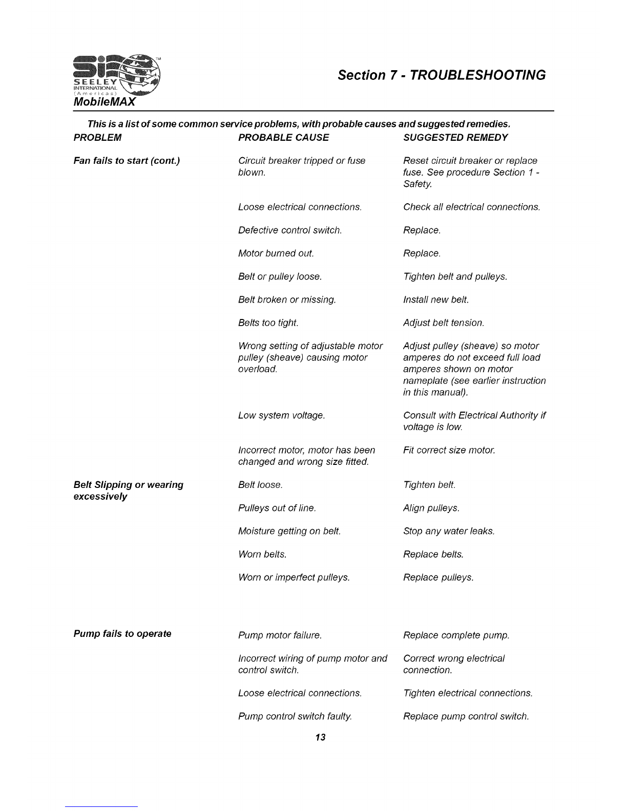
This is a list of some common service problems, with probable causes and suggested remedies.
PROBLEM
Fan fails to start (cont.)
Belt Slipping or wearing
excessively
PROBABLE CAUSE
Circuit breaker tripped or fuse
blown.
Loose electrical connections.
Defective control switch.
Motor bumed out.
Belt or pulley loose.
Belt broken or missing.
Belts too tight.
Wrong setting of adjustable motor
pulley (sheave) causing motor
overload.
Low system voltage.
Incorrect motor, motor has been
changed and wrong size fitted.
Belt loose.
Pulleys out of fine.
Moisture getting on belt.
Worn belts.
Worn or imperfect pulleys.
SUGGESTED REMEDY
Reset circuit breaker or replace
fuse. See procedure Section 1 -
Safety.
Check all electrical connections.
Replace.
Replace.
Tighten belt and pulleys.
Install new belt.
Adjust belt tension.
Adjust pulley (sheave) so motor
amperes do not exceed full load
amperes shown on motor
nameplate (see earlier instruction
in this manual).
Consult with Electrical Authority if
voltage is low.
Fit correct size motor.
Tighten belt.
Align pulleys.
Stop any water leaks.
Replace belts.
Replace pulleys.
Pump fails to operate Pump motor failure.
Incorrect wiring of pump motor and
control switch.
Loose electrical connections.
Pump control switch faulty.
13
Replace complete pump.
Correct wrong electrical
connection.
Tighten electrical connections.
Replace pump control switch.

Section 7- TROUBLE SHOOTING
This is a list of some common service problems, with probable causes and suggested remedies.
PROBLEM PROBABLE CAUSE SUGGESTED REMEDY
Pump fails to operate (cont.) Insufficient water in pan/tank. Refill water tank.
Pump strainer blocked. Clean strainer.
Blocked water tubing. Clean the tubing.
Foreign material lodged in the
"water spreader/s" Remove spreader/s and clean out
foreign material.
Noisy Air Cooler Fan out of balance due to dirt, etc. Clean fan.
Cooler delivering more air than
needed. Adjust motor pulley (sheave) to
slow down fan.
Belt "squealing',. Tighten belt by adjusting motor.
Apply belt dressing to belt. In some
cases it may be necessary to
replace belt or pulley.
Water being thrown into room Loose water tubing connections. Tighten all connections.
Break in water tubing. Replace any cracked or broken
tubing.
Pads not properly installed in pad
frames. Make sure pads are properly
installed.
Incorrect or damaged pads fitted. Replace with the manufacturer's
recommended pads.
Overflow of water Float valve not sealing properly. Clean or replace valve washer.
Unpleasant Odour New cooler pads. Run pump continuously for a while
to flush the pads.
Cooler located near source of
unpleasant odor. Remove source of odor or place a
barrier between cooler and source
of odor.
Algae in pan/tank water. Drain pan/tank and clean
thoroughly. Fill with fresh water.
Install new pads.
Pads remain wet after shut down. Allow fan to run for about ten (10)
minutes after pump is shut off to
dry out pads.
Rapid formation of white
deposits on Pads and Louvres High mineral content of supply
water. Drain water from tank more
regularly and refill with fresh water.
14
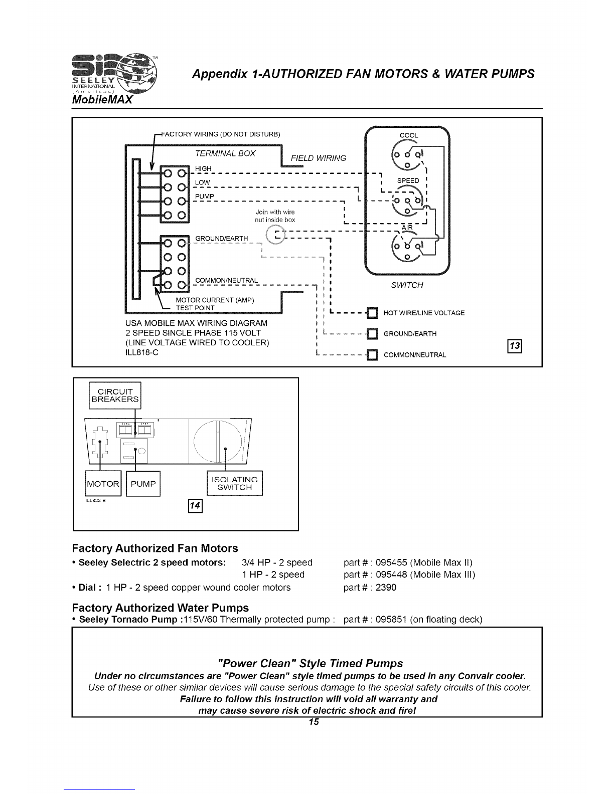
Appendix 1-AUTHORIZED FAN MOTORS & WATER PUMPS
(DO NOT DISTURB)
m
TERMINAL BOX IFIELD WIRING
HIGH
PUMP
GROUND/EARTH
COMMON/NEUTRAL
MOTOR CURRENT (AMP)
TEST POINT
USA MOBILE MAX WIRING DIAGRAM
2 SPEED SINGLE PHASE 115 VOLT
(LINE VOLTAGE WIRED TO COOLER)
ILL818-C
SWITCH
D HOTWIRE/LINE VOLTAGE
_'D GROUND/EARTH
D COMMON/NEUTRAL
CIRCUIT
BREAKERSJ
tLL822-B %ISOLATING
SWITCH
Factory Authorized Fan Motors
•Seeley Selectric 2 speed motors: 3/4 HP - 2 speed
1 HP- 2 speed
• Dial : 1 HP - 2 speed copper wound cooler motors
Factory Authorized Water Pumps
•Seeley Tornado Pump :115V/60 Thermally protected pump •
part # 095455 (Mobile Max II)
part # 095448 (Mobile Max III)
part # •2390
part # •095851 (on floating deck)
"Power Clean" Style Timed Pumps
Under no circumstances are "Power Clean" style timed pumps to be used in any Convair cooler.
Use of these or other similar devices will cause serious damage to the special safety circuits of this cooler.
Failure to follow this instruction will void all warranty and
may cause severe risk of electric shock and fire!
15
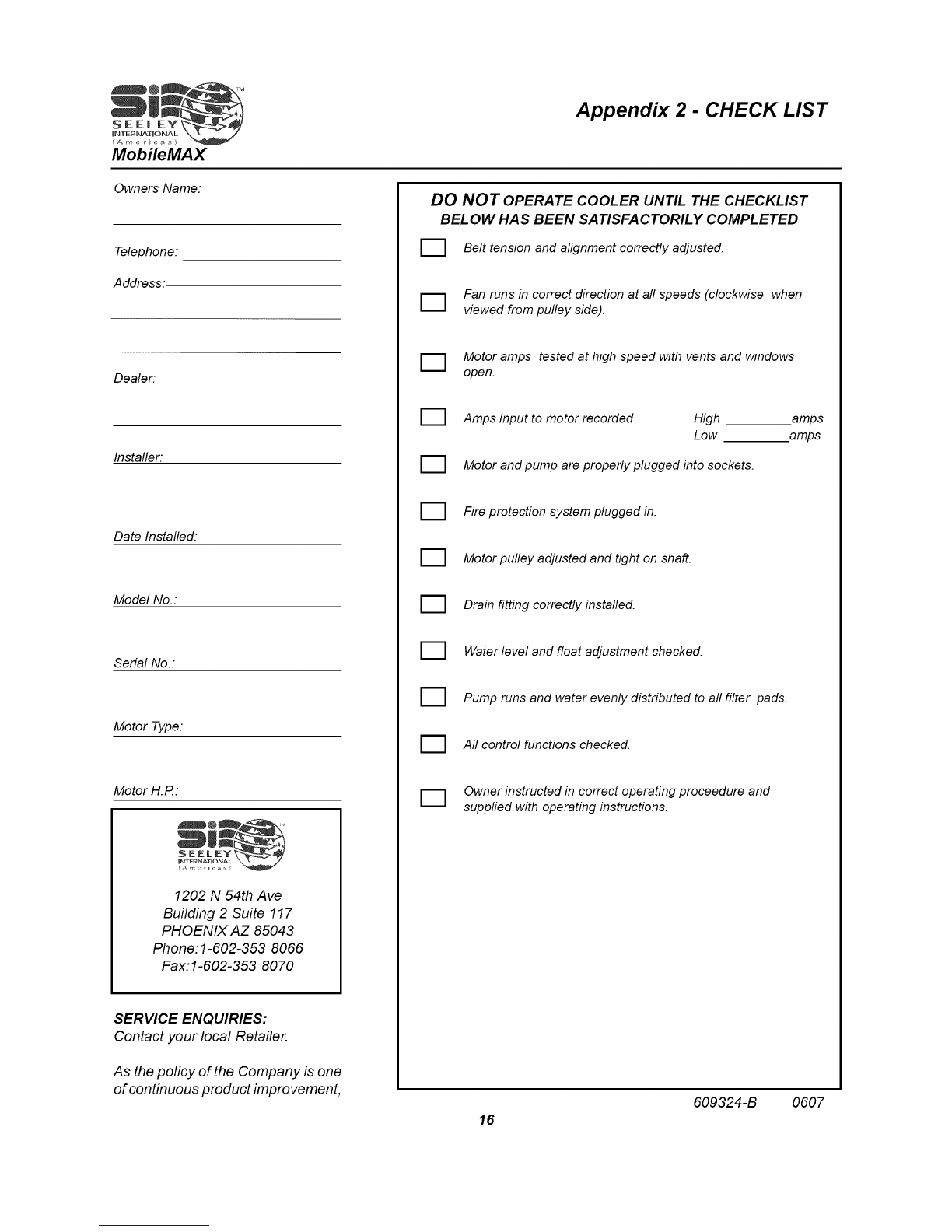
Owners Name:
Appendix 2 - CHECK LIST
Telephone:
Address:.
Dealer:
Installer:
Date Installed:
Model No.:
Serial No.:
Motor Type:
Motor H.R:
1202 N 54th Ave
Building 2 Suite 117
PHOENIX AZ 85043
Phone:l-602-353 8066
Fax:l-602-353 8070
SERVICE ENQUIRIES:
Contact your local Retailer.
As the policy of the Company is one
of continuous product improvement,
D
Belt tension and alignment correctly adjusted.
Fan runs in correct direction at all speeds (clockwise when
viewed from pulley side).
Motor amps tested at high speed with vents and windows
open.
Amps input to motor recorded High amps
Low amps
Motor and pump are properly plugged into sockets.
Fire protection system plugged in.
Motor pulley adjusted and tight on shaft.
Drain fitting correctly installed.
Water level and float adjustment checked.
Pump runs and water evenly distributed to all filter pads.
All control functions checked.
Owner instructed in correct operating proceedure and
supplied with operating instructions.
16 609324-B 0607
DO NOT OPERATE COOLER UNTIL THE CHECKLIST
BEL OW HAS BEEN SATISFACTORILY COMPLETED
This manual suits for next models
1
Table of contents


