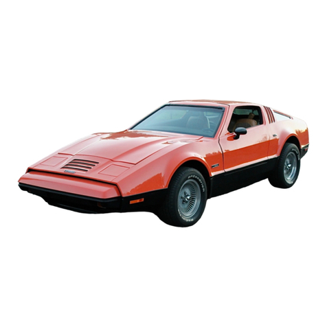
Bricklin EV-1 User manual

Bricklin EV-1 Owner's Manual
The Bricklin EV-1
Design Specifications and Owner's Manual
DRAFT Page 1 of 31 DRAFT

Bricklin EV-1 Owner's Manual
For further information, contact:
NetGain Motors, Inc.
800 South State St.
Lockport, IL 60441
(630) 243 9100 Office
(630) 686 4054 Fax
http://www.go ev.com
DRAFT Page 2 of 31 DRAFT

Bricklin EV-1 Owner's Manual
Table of ontents
Introduction..............................................................................................................................................................5
How the ricklin Was Chosen............................................................................................................................5
atteries...............................................................................................................................................................5
attery Management System..............................................................................................................................7
Power...................................................................................................................................................................8
Controller Selection..........................................................................................................................................10
Range.................................................................................................................................................................11
Charging System...............................................................................................................................................12
Transmission.....................................................................................................................................................13
Gauges & Instrumentation................................................................................................................................14
Torque – Android App.......................................................................................................................................14
WarP-Drive Interface Module...........................................................................................................................16
Operating Notes and Suggestions..........................................................................................................................17
Gear Selection...................................................................................................................................................17
Driving..............................................................................................................................................................18
Range.................................................................................................................................................................18
Operating the Heater and Defroster..................................................................................................................19
raking..............................................................................................................................................................19
Emergency Disconnect......................................................................................................................................20
Charging ...........................................................................................................................................................21
Charging Costs..................................................................................................................................................24
Fast Charging....................................................................................................................................................24
Cooling System.................................................................................................................................................25
Tire Pressure......................................................................................................................................................26
Maintenance......................................................................................................................................................26
ricklin SV-1 History............................................................................................................................................31
1975 ricklin SV-1 Specifications....................................................................................................................31
ricklin EV-1 History............................................................................................................................................32
1975 ricklin EV-1 Specifications....................................................................................................................32
Performance......................................................................................................................................................33
Original ricklin SV-1 Performance vs EV-1 Performance..............................................................................33
DRAFT Page 3 of 31 DRAFT

Bricklin EV-1 Owner's Manual
Illustration Index
Illustration 1: Example of 16, LiFePO4 prismatic cells with MS.........................................................................6
Illustration 2: attery Management System - single cell module............................................................................7
Illustration 3: NetGain Motors, Inc - WarP 11 Motor..............................................................................................9
Illustration 4: Dual WarP 11 Motors coupled to transmission.................................................................................9
Illustration 5: WarP-Drive Industrial - Motor Controller.......................................................................................10
Illustration 6: NetGain Controls, Inc. - PulsaR, Power Distribution Unit (PDU)................................................12
Illustration 7: ricklin EV-1 FMX Transmission..................................................................................................14
Illustration 8: Rechargecar.com - Fuel measuring device......................................................................................14
Illustration 9: Android Torque application showing various gauge types.............................................................15
Illustration 10: O D-II to luetooth Adapter........................................................................................................16
Illustration 11: NetGain Controls, Inc. - WarP-Drive Interface Module...............................................................16
Illustration 12: EV West Accessory Plate & Pump System...................................................................................19
Illustration 13: Emergency Disconnect Switch (the IG red button)....................................................................20
Illustration 14: Typical charging plug used on electric vehicles............................................................................21
Illustration 15: 240 VAC to 120 VAC power cord adapter....................................................................................22
Illustration 16: J1772 Plug and outlet....................................................................................................................22
Illustration 17: NEMA 14-50 240 VAC plug.........................................................................................................23
Illustration 18: Motor Temperature Gauge............................................................................................................25
Illustration 19: ricklin EV-1 High Voltage Power Distribution...........................................................................28
Illustration 20: ricklin EV-1 Wiring Diagram.....................................................................................................29
Illustration 21: ricklin EV-1 12 VDC Power Distribution...................................................................................30
DRAFT Page 4 of 31 DRAFT

Bricklin EV-1 Owner's Manual
Introduction
How the Bricklin Was hosen
I have been the owner of a 1975 Bricklin since 1976. When I initially purchased the vehicle it had
approxi ately 5,000 iles on the odo eter. The Bricklin was y daily driver for a couple of years,
and then it began to sit for longer and longer periods of ti e. For any years it resided in y garage
doing nothing ore than taking up uch needed space.
At one point I decided to take the Bricklin to Michigan to have air-doors and a console installed. Upon
returning, it sat in the garage again. When I finally began to drive it, I found that it was not running
very well. I decided to have it brought back to life, in a ore invigorated for . I had the engine
rebuilt, added a 4BBL Holley carburetor, alu inu high-rise anifold, headers, alu inu radiator,
and other iscellaneous ite s (i.e. new brakes, fluids, etc.). I also decided to change the original
color fro “suntan” to another original color, “white”. I prepaid for all the work. After five years the
vehicle was returned by the shop that perfor ed the above entioned work. I learned a valuable
lesson about paying for the work perfor ed in advance of the work actually being perfor ed.
Though I had hoped the perfor ance would be greatly i proved, it turned out the work was very sub-
standard. After >$15,000 the vehicle barely ran without dying, and the paint job was seriously flawed.
I was quite disenchanted, and the vehicle went back to the garage space it had beco e accusto ed
to. After 37 years the 1975 Bricklin still had less than 34,000 original iles.
Unlike the Bricklin, I continued to work, and to build a new co pany renown for powerful electric
otors co only used in converting vehicles fro gasoline burning internal co bustion engines, to
pure electric otor power. Series wound, brushed DC Motors are capable of producing enor ous
a ounts of torque at stall speed. A single WarP 11 otor has a peak stall torque of 1,959 ft-lbs. - if
you could provide it with enough a perage (~3,951 A ps). The a ount of torque developed is
based upon the A perage squared (I²). Si ply put, if you double the a perage you quadruple the
torque – at least until saturation occurs at which ti e the torque increase beco es linear. The
voltage supplied to the otors deter ines the RPMs the otor will spin at. This is a nearly linear
relationship. If you double the otors voltage, you will double the RPMs, and thus the HP (Horse
Power). Actually, it is slightly ore than double since ost losses are fixed. There are li its as to
how uch voltage and a perage these otors can sustain, but they are quite robust.
Using early versions of these powerful electric otors a battery powered dragster was developed that
was capable of 60' ti es under one second (.986). Unfortunately, the lead-acid or PbA batteries of
the late 1990's were not capable of sustaining the power level needed to aintain that rate of
acceleration for ore than a few seconds. Even so, the vehicle was capable of 10 second ¼ iles
nearing 130 MPH.
Batteries
Super-capacitor testing was perfor ed in the dragster in conjunction with NASA Illinois and the NASA
Glenn Research Center. When the super capacitors were connected in parallel to the battery pack,
they beca e slaves of the batteries. This eant that they could not output any power exceeding
what the PbA batteries were capable of. But, the testing of the super capacitors did lead us to
another new battery technology generally referred to as Lithiu che istry based batteries.
DRAFT Page 5 of 31 DRAFT

Bricklin EV-1 Owner's Manual
In the late 1990's lithiu batteries developed a rather poor reputation for catching fire in laptop
co puters. But, technology has arched forward, and today's Lithiu -Iron-Phosphate cells, when
used in the proper anner, have shown that they are uch ore robust and safer than the batteries
of a decade before.
The LiFePO4 batteries provide enough power to triple the range of electric vehicles that were
powered by PbA batteries. Additionally, lithiu batteries have an extre ely long life, are not as
affected by hot or cold te peratures as PbA , are lighter than PbA, ore powerful than PbA, display
no e ory effect, and have high discharge and charge rates. The downside of the LiFePO4
batteries is that they cost approxi ately two to three ti es the cost of PbA batteries. Due to their
long life they are actually less expensive then using PbA when a ortized over ti e.
For the Bricklin EV-1, a quantity of 48, 3.65 Volt, LiFePO4 pris atic cells rated at 160 A p hours
each were chosen. The original gas tank was re oved and 18 of the cells were placed in a
replace ent box located in the original gas tank position and arranged in a si ilar anner to those
shown in the Illustration below.
The rest of the cells (30) are arranged under the hood of the vehicle and above the electric otor. All
of the cells were connected in series to provide a fully charged pack voltage of 172.8 Volts (48 * 3.6).
The cells weigh 11.53 pounds (5.23 kg) each and are 6.65” W X 3.35” D X 9.72” H (169 X 85 X 247
).
The cells are rated at 3C which eans they can output 3 ti es their A pere-hours rating, or 480
DRAFT Page 6 of 31 DRAFT
Illustration 1: Example of 16, LiFePO4 prismatic cells with BMS

Bricklin EV-1 Owner's Manual
A ps continuously. For short bursts they are capable of 1280 A ps (8C) for 5 seconds, 800 A ps
(5C) for 15 seconds and 800 A ps (5C) for 60 seconds. They have a life cycle of 2,000 at 80%
Depth of Discharge (DOD). Lower DOD will extend the life of these batteries, while 100% DOD will
shorten their life to approxi ately 1,000 cycles.
Battery Management System
To ensure that the expensive battery pack is properly balanced and protected, a Battery Manage ent
Syste or BMS has been installed. It is critical for safety and perfor ance that the cells be well
balanced both on charge and discharge. Every cell in the battery pack ay not need the exact sa e
a ount of energy restored when a battery pack is charged. Si ilarly, when cells are discharged,
so e cells ay be depleted quicker than others.
These conditions ay be due to slight variances in the anufacturing process, or by the
interconnects within the battery pack – such as loose or corroded connections. Even subtle
differences, such as the place ent of the cells can affect the perfor ance of a cell due to
te perature. Batteries surrounded by other cells will heat up quicker and stay war longer, while
cells on the end of the pack will generally cool quicker. Though the differences are relatively s all,
over ti e, they can have a cu ulative effect on the overall condition of the battery pack or individual
cells.
The BMS helps ensure that no cell in the pack is over charged and also that no cell falls below a
predeter ined low Depth Of Discharge (DOD) state, in the case of the Bricklin EV-1 the low cut-off
discharge of each cell should be 2.5 Volts (120 Volts). For additional safety, this has been adjusted
to 2.6 Volts (~125 Volts).
Once a cell reaches 3.5 Volts the BMS shunts any current provided to a cell to other cells, or if all
cells are charged, si ply signals a shut off to the charger.
When the vehicle is being driven and a cell (or pack) drops below a predeter ined ini u a
audible buzzer will sound to notify the driver of the low cell or pack condition. Running cells, or the
pack, below the established ini u s can seriously da age the battery pack, individual cells, and
possibly other electronic controls, and even the otor. Care ust be exercised to ensure the battery
pack is aintained in proper working order.
DRAFT Page 7 of 31 DRAFT
Illustration 2: Battery Management System single
cell module

Bricklin EV-1 Owner's Manual
Power
The progress in power electronics and electric otor controls has advanced by leaps and bounds
over the past decade. Pulse Width Modulated (PWM) high power DC otor controllers that are
capable of >3,500 A ps at >400 Volts (~1,400 kW) are readily available. And, unlike the controllers
of the 1980's and 1990's, the new generation of high power otor controllers are safe and s ooth in
operation.
What does this 1,400 kW really equate to? Well, the for ulas work like this:
Watts = (Volts * Amps)
HPe1 = (Watts / 746)
The result would be:
Watts = (400 * 3500)
HPe = (1,400,000 / 746) or 1,877 HPe
But, realistically, you need to account for the losses (efficiency) of the electrical syste . It would be
easier, and closer to reality to say:
HPe = (1,400,000 / 1000) or 1,400 HPe (after losses)
Unlike Internal Co bustion Engine (ICE) vehicles that produce torque and HP that is usually nearly
equivalent to one another (~1 HP to ~1 ft lb), it should be noted that the type of electric otor being
used in the Bricklin EV-1 produces al ost 2 ft. lbs of torque per HP produced.
As a side note, echanical horsepower is calculated as:
HPm2 = ( ( Ft. Lbs * RPM ) / 5252 )
Motor Selection
Even though the NetGain Motors, Inc. WarP Motors are recognized as the ost robust production
otors for EV applications, a single otor cannot handle the potential a ount of input power fro
these extraordinarily powerful otor controllers for ore than a few illiseconds (not to ention the
i pact on the rest of the drive-line).
To avoid destroying the otors (and the drive-line), it is quite co on to utilize:
•lower power settings on the otor controller,
•lower power otor controllers,
•larger and ore powerful otors,
•ultiple otors to share the power,
•so e co bination of the above options.
1 HPe = Horsepower electrical
2 HP = Horsepower echanical
DRAFT Page 8 of 31 DRAFT

Bricklin EV-1 Owner's Manual
In the case of the Bricklin EV-1 we choose to use a lower power otor controller as well as a larger
single otor. The co bination used in the Bricklin EV-1 will be a standard WarP 11 Motor powered
by a single 1,400 A p NetGain Controls, Inc. WarP-Drive Industrial Controller.
A single otor is ore than adequate for the Bricklin when coupled to the original Bricklin FMX
trans ission. Multiple otors were considered and offer so e advantages. Besides “sharing” the
workload and providing a “backup” in case of a single otor failure, dual otors [when powered by a
single controller] ay be wired together either in series or on parallel.
In series ode both otors will see full a perage, but only ½ the voltage. This ode provides
axi u torque. When wired in parallel, both otors see ½ the a perage and full voltage. This
ode produces axi u horsepower. It is possible to control the switch between series and parallel
with the flip of a switch.
DRAFT Page 9 of 31 DRAFT
Illustration 3: NetGain Motors, Inc WarP 11 Motor
Illustration 4: Dual WarP 11 Motors coupled to
transmission

Bricklin EV-1 Owner's Manual
It would be a possible to add a second otor and controller and double the power potential, but this
vehicle is being built as a daily-driver, so so e restraint ust co e into play. Additionally, the
weakest link ust always be considered, and dual controllers ight require a stronger battery pack
then the one being used, and it is unlikely the rear differential could withstand 830+ ft. lbs of torque.
ontroller Selection
The selection of the high power otor controller was ade based upon a nu ber of design criteria.
Since the controller is being used in an auto otive environ ent it ust be of auto otive quality and
support CANbus as well as OBD-II. OBD-II was not required in vehicles until 1996 and since the
1975 Bricklin did not require OBD-II, this is a significant upgrade to the vehicle. This auto otive
quality require ent significantly narrowed the search for viable controllers.
As the controller will be placed under the hood of the vehicle it ust be able to withstand a potentially
harsh environ ent - it ust also be as watertight as possible.
All high power connections ust be protected fro the environ ent, as well fro anyone who
decides to poke around under the hood. The WarP-Drive Industrial otor controller is the only
controller on the arket that provides these features. Additionally, the gland nuts used to pass all
cables into the inside of the controller provide stress relief, as well as being watertight.
An additional feature required is the ability to “idle” the electric otor when the vehicle is in a “run
state”. This is necessary to power auto atic trans issions, as well as running so e “appliances”
such as a power steering pu p, air conditioning or even an alternator to keep the 12-Volt battery
syste charged.
DRAFT Page 10 of 31 DRAFT
Illustration 5: WarP Drive Industrial Motor Controller

Bricklin EV-1 Owner's Manual
The power to offer perfor ance exceeding the original vehicle required that the controller be of a
liquid cooled design.
The WarP-Drive Industrial is the only controller on the arket that could eet all of these
require ents as well as providing additional flexibility which includes the ability to be field upgraded to
higher power levels through a fir ware download over the Internet.
So e of the additional features include:
•160/260/360 Volt DC input capability (field upgradeable via software download)
•1000/1200/1400 A ps available (field upgradeable via software download)
•550 A ps continuous rating with 1.5 GPM liquid cooling
•Di ensions: 22x7x4 in.
•Weight: 23 lbs .
•Built-in precharging
•Dual CANbus ports
•Fil capacitors in the power section
•Co pletely sealed device.
•Battery connections on one end, otor connections on the other for added safety
•1/2” OD copper tubing for liquid cooling
•dual current sensors for added safety
•co pletely isolated throttle channels for added safety
Range
We can obviously produce ore than adequate horse-power and torque, but one of the concerns
people who are considering an electric vehicle have is RANGE! In the industry we refer to this as
“range anxiety”. The range of the vehicle can no longer be calculated as iles per gallon, rather a
ore co on calculation is kW/ ile. There are nu erous factors that will deter ine the range.
So e of the factors that ust be considered are, coefficient of drag, frontal area, rolling resistance,
speed on level terrain, speed on grade, the percent grade, gear ratios, and tire dia eter, drive-train
efficiencies, te perature (which affects viscosity of fluids), and other factors. The rate of acceleration
also plays a significant roll in range, as does the axi u speed.
For the Bricklin EV-1 we are targeting a conservative range of 75 iles at 50 MPH. The range would
be increased if traveling on level terrain without any stops at 45 MPH. Likewise, it will be significantly
decreased if traveling at 75 MPH on hilly terrain, or if aking very quick starts.
The energy needed to accelerate ass over ti e is quite significant. Therefor, rapid 0 -60 MPH
acceleration, though possible, will have a significant i pact on the range. This holds true with ICE
vehicles as well, though the abundance of fuel stations akes it fairly convenient to refuel.
DRAFT Page 11 of 31 DRAFT

Bricklin EV-1 Owner's Manual
Maintaining a particular speed (on level terrain) requires far less power then it takes to obtain the
speed. For instance, the reason you need 300 HP (and 300 ft. lbs. of torque) in your nor al daily
driving vehicle is to allow you to accelerate the vehicles ass quickly and obtain the desired speed
quickly. Once the vehicle reaches approxi ately 60 MPH, on level terrain, it nor ally requires only
20 -30 HP to aintain the speed. Depending upon the grade of the road, speed, the road surface,
and other factors, it ight require ore than twice that horsepower to cli b a hill.
Most internal co bustion engine vehicles are designed in such a anner that the crankshaft is
spinning around 2,000 RPMs at 60 MPH. At this speed and RPM the ICE engine is close to it's
opti u efficiency – around 25% (usually less, and an average efficiency that is far less). The
electric otors can reach efficiencies of greater than 90%. Plus, when the electric vehicle is stopped
at a stoplight, the electric otor is generally not receiving any power – unless it is necessary to idle
the electric otor to power “appliances” as stated previously.
harging System
The Bricklin EV-1 utilizes the latest technology for charging its LiFePO4 battery pack. A Power
Distribution Unit (PDU) known as the PulsaR has been designed and anufactured by NetGain
Controls, Inc. and is carried on-board the vehicle. This unit is also used to power the original 12-Volt
electrical syste of the vehicle (lights, radios, etc.) It acco plishes this by converting the high voltage
traction pack to ~12 VDC and keeping the original 12-Volt battery fully charged.
This liquid cooled PDU unit is ore than just an extre ely powerful battery charger. This unit utilizes
CANbus co unications, and can use AC input to charge the batteries at up to 24kW, but also
provides DC fast charging capability of up to 150kW. This capability would nor ally be acco plished
fro electric vehicle to electric vehicle, or fro a stationary battery pack to the vehicle battery pack.
This high power capability also eans that it will be able to use future charging ethods fro auto
anufacturers that have not been officially released.
The selection of the charger was based upon si ilar criteria as the otor controller selection. The
only charger available that et (exceeded) the criteria is the PulsaR Power Distribution Unit fro
NetGain Controls, Inc.
DRAFT Page 12 of 31 DRAFT
Illustration 6: NetGain Controls, Inc. PulsaR, Power Distribution
Unit (PDU)

Bricklin EV-1 Owner's Manual
The features of the PulsaR unit include:
•Works with up to 370 Volt DC battery pack
•500 A p controller (optional, and not included in the Bricklin EV-1)
•Up to 24 kW AC Charging
•Internal DC-DC converter with up to 53 A ps provided to high quality connector, voltage
adjustable fro 12 to 15 Volts via tri pot
•DC fast charge up to 150 kW
•Liquid cooling with large ½ in. dia eter tubes for low pressure drop
•Native J1772 co patibility
•All contactors built in
•Di ensions: 18.5 x 14.5 x 5.5 inches
•34 lbs. total weight
•Built-in precharging
•CANbus
•Fil capacitors in the power section
•Co pletely sealed device with cable glands for all power cable connections and high quality
waterproof connectors for all other wiring
•Intelligent PWM control for external otor blower
•Liquid cooling pu p control output
•Provision for charging to/fro external battery pack to/fro traction pack
Transmission
As previously entioned, the electric otors are extre ely powerful and ay be rotated in either a
clock-wise or counter-clockwise rotation. For this reason, any people believe a trans ission is not
required. But, reverse rotation is not opti al for the WarP Motor design, so having a trans ission
allows for easy reversing of the vehicle as well as other advantages.
Direct drive applications also introduce a safety risk. If there were a catastrophic failure in the
electrical syste that caused the otors to see full battery pack power, there would be no way to stop
the vehicle. The otors would have no proble overpowering the brakes, and unless a fuse blew or
a safety switch was successfully thrown, there would be no way of stopping the otors.
A trans ission allows for a anual disconnect in extraordinary situations. Although the otors have
the torque to get the vehicle oving, they will draw far ore a perage for a longer period of ti e
without a trans ission. As with ICE engines, the otors have a sweet-spot where they like to
operate. This is nor ally in the 2,000 - 4,000 RPM range. The rule-of-thu b for these electric
otors is: the electric otors are ost efficient when run about 1,000 RPMs higher per gear than the
ICE engine.
DRAFT Page 13 of 31 DRAFT

Bricklin EV-1 Owner's Manual
The trans ission also provides a “Park” position that locks the trans ission. Since the otors
nor ally spin freely, parking on a hill without a trans ission is not easily acco plished unless there is
a parking brake. The original Bricklin SV-1 utilized a echanical drive speedo eter driven by a cable
to the trans ission. This sa e cable is used and akes it quite si ple to aintain the original
speedo eter. It is also possible to use a GPS speedo eter.
Illustration 7: Bricklin EV 1 FMX Transmission
Gauges & Instrumentation
An electric vehicle driver should be aware of what the vehicle is doing in a
si ilar anner to the original ICE vehicle. This requires the replace ent or
addition of so e gauges. An oil pressure gauge is no longer required, but
a gauge to display a perage the otor is receiving is quite useful. Though
the engine coolant te perature is no longer needed, it ay be useful to
onitor the coolant te perature of the otor controller and/or battery
charger. The WarP Motors also provide a ther istor to allow onitoring
the internal otor te perature. The existing fuel gauge can be converted
using a Coulo b counting device so that the driver has a visual display of
the fuel available (battery State Of Charge SOC).
Torque – Android App
A tacho eter should be connected so that the otor RPMs ay be onitored.
Other gauges that ay be useful are: otor voltage, battery pack voltage, otor a perage, and
battery pack a perage. Since we are trying to preserve the original instru entation cluster while
adding the new instru entation needed we have chosen to use an Android based tablet display and
an application called “Torque”. Torque is a very versatile application that allows the Android tablet to
display various OBD-II infor ation in a wide variety of displays, such as analog sweep gauge, digital
gauge, graphs, etc. If the Android device is GPS enabled, Torque can also display the GPS speed.
Torque can also be used to display (and record) RPMs or any data supplied by the WarP-Drive
Industrial Controller or PulsaR Power Distribution Unit.
DRAFT Page 14 of 31 DRAFT
Illustration 8:
Rechargecar.com Fuel
measuring device

Bricklin EV-1 Owner's Manual
Illustration 9: Android Torque application showing various gauge types
Torque allows you to view live OBD-II otor and controller data on your Android phone or tablet.
So e of the features of Torque are:
•Fully custo izable dashboard screens - Design your own layouts and custo dials, use your
own the es
•Retrieve Fault Codes (DTCs) and clear Check Motor lights - View fault descriptions using the
built-in databases
•Upload live OBD-II data to your web server or the torque web viewer in real-ti e
•Check the perfor ance of your vehicle with BHP / Torque / 0 -60 & Quarter Mile widgets
The “Torque” application receives infor ation fro a Bluetooth OBD-II device. Unfortunately, since
the Bricklin SV-1 predates OBD and OBD-II specifications, it is necessary to add a Bluetooth OBD-II
device that connects to the otor controller and is driven off of the CANbus. Since the WarP-Drive
Industrial Motor Controller and PulsaR Power Distribution Unit are both CANbus enabled, it is a trivial
atter to enhance the dashboard of the Bricklin EV-1 with a co pletely digital dashboard. In
actuality, we have chosen to keep as any of the original gauges intact as possible. Where
necessary, the original gauges have been “enhanced” to provide si ilar infor ation as they originally
did, for instance the fuel gauge has been updated with a Coulo b counting device. To handle the
additional gauges in a si ple and consistent anner, the Android tablet works very well.
DRAFT Page 15 of 31 DRAFT

Bricklin EV-1 Owner's Manual
Illustration 10: OBD II to Bluetooth
Adapter
WarP-Drive Interface Module
It is also possible to add a NetGain Controls, Inc.
Interface Module (IM) to the vehicle. The “IM”
odule ay be ounted on the windshield, or
built-in, or not used at all, depending upon the
drivers needs. The IM odule is an alternative to
the Android based Torque application. It should
be noted that in order to upgrade the WarP-Drive
Industrial software an “IM” odule is required.
Many of the EV conversion shops will upgrade the
software using their IM odule, or loan the IM
odule to so eone that needs to update their
fir ware.
The IM odule has nu erous features, including:
•Data logging to a ini-SD card fro all
internal sensors in the WarP-Drive. So e of the internal sensors are: otor current, voltage,
battery current, battery voltage, chill plate te perature, pulse width, throttle position, internal
power supply voltages, external supply voltage, error and warning codes, and controller
operating state. Data can then be viewed on a co puter which accepts an SD card using the
included adapter.
•Fir ware upgrades to the WarP-Drive controller.
•Real-ti e display of the above data para eters on a variety of screens.
•Real ti e clock with super-capacitor battery backup. Set the ti e once, and even when
unplugged, the ti e will be accurately kept.
•Easy in-vehicle ounting using a windshield suction-cup ount (provided).
•Powered over the connection to the WarP-Drive so only a single cable is required to operate.
•Extre ely sleek and co pact design fits co fortably in your hands.
•The interface odule's fir ware can easily be updated by si ply obtaining the new fir ware
file by download, copying the upgrade files to the ini-SD card, inserting the card into the
DRAFT Page 16 of 31 DRAFT
Illustration 11: NetGain Controls, Inc. WarP Drive
Interface Module

Bricklin EV-1 Owner's Manual
Interface Module, and power cycling the unit. Seconds later, the unit is running with upgraded
fir ware.
•Settings are saved to non-volatile e ory so powering up after disconnecting fro power will
provide previously set configuration
Operating Notes and Suggestions
Driving an electric vehicle is very si ilar to driving any nor al ICE vehicle. But there are so e
interesting differences and subtleties that can enhance your experience. Most of these derive fro
the very low noise levels and the lack of engine co pression you ay be fa iliar with in driving an
ICE powered vehicle. The Bricklin EV-1 is a true plug-in electric, battery powered vehicle – not a
hybrid.
Starting
There is really no analog to “starting” with an electric vehicle. To drive, you do have to “turn on” the
vehicle by applying voltage to the controller. But it always starts and there is little indication that it is
“running” until you step on the throttle.
It is a good idea to place the gear selector in neutral and apply the hand brake before energizing the
syste .
Turn the ignition key two detents to clockwise (right). You ay here a “CLICK” as the ain power
contactors are closed. When you release the key fro this position, it should return to the run
position. A single red indicator light should light on the dash indicating the vehicle is ready for
operation. If you are running Torque on an Android tablet, the display should provide you with status
indicators. You ay also hear so e very quiet, but audible sound fro the coolant pu p, heat
exchanger fan, and forced air cooling fan for the DC otor in the engine co part ent.
Gear Selection
The Bricklin EV-1 uses the original AMC Model 20, 8.9”, 3.15:1 differential [to be verified] as was
used in the original Bricklin SV-1 vehicle. To power the vehicle in the reverse direction, you will need
to place the trans ission into reverse. Depress and hold the brake pedal as you pull the shift lever
back into the reverse location. Gently depress the throttle keeping in ind that the vehicle has
enor ous power potential.
The re aining gears are 1st, 2nd and 3rd identical to the original Bricklin SV-1. A straight back and forth
configuration with 1st gear forward, and 2nd gear when pulled back, and 3rd gear when pulled
co pletely down. It should be noted that it is possible to start fro a dead-stop in 2nd gear, but it is
easier on the otor, batteries and controller if you start in 1st gear. The ain difference between the
use of the original Bricklin SV-1 trans ission and its use in the Bricklin EV-1 is that the trans ission
ust be down-shifted MANUALLY! If you do not return the gear selector lever to 1st gear when you
co e to a stop after driving in 3rd gear, it will re ain in 3rd gear, so when you start up it will be fro 3rd
gear. This ay take a bit of getting used to. There is no clutch in this vehicle, it is a fully auto atic,
anual shifting of the gears.
It would be possible to replace the original rear differential gear ratio to obtain greater acceleration, or
to obtain a higher top speed. Though the otor is capable of a top speed of ~5,500 rp , it is nor ally
DRAFT Page 17 of 31 DRAFT

Bricklin EV-1 Owner's Manual
electronically li ited to 5,000 rp . You will quickly ascertain that first gear is si ply needed to assist
the start-up, especially on inclines, but 2nd gear is all that is nor ally needed up to 45-50 MPH.
With an electric vehicle, you should never use the electric otor to “hold a position” on an incline.
Use the brakes to hold the vehicles position. Using the electric otor to aintain a position on an
incline ay possibly da age the electric otor, though with an auto atic trans ission this da age
potential is greatly alleviated.
Driving
Take care during acceleration your first few weeks of driving this car. A great deal of the sense of
speed and acceleration is derived fro the “roar of the engine” we are accusto ed to in ICE vehicles.
There is no roar fro an electric vehicle and you can find yourself exceeding the speed li it in just a
few seconds.
Si ilarly, there is no engine co pression to slow you down when you take your foot off the throttle.
The vehicle rolls freely down the road with no electric power applied and you will quickly learn to glide
long distances using no energy at all, in any cases actually accelerating in even slight downhill
terrains.
Be aware that subli inally we are all acculturated to the sound of auto obiles. We’ve been around
the all our lives. And, they ake a very recognizable sound. This vehicle does not ake that sound.
Be on the alert for pedestrians, children, pets, and even wildlife. It ay be necessary to honk the
horn to alert people nearby of your approach or to install a sound syste that warns others of your
approach.
Range
We rate the Bricklin EV-1 as a 75- ile vehicle. We have several indicators to re ind you what your
State Of Charge or SOC is at all ti es. And, in the event you discharge it too far, the vehicle will
auto atically go into “li p ode”, and an audible buzzer will sound. In li p ode you can still drive
the vehicle, but the throttle input is cut to a fraction of its nor al value, and it can take several painful
inutes to accelerate to 30 ph. This allows you to “creep” or “li p” to a safe area out of traffic or a
nearby place where you can recharge the cells sufficiently to proceed.
The actual range you get will vary dra atically depending on your driving style. Higher speeds take
greater energy to overco e the wind resistance, so at 70 ph you will not likely achieve 75 iles –
perhaps 50. Strong accelerations also consu e ore energy. Use of the electric defroster/heater and
air-conditioner will also use energy – reducing range slightly.
If range is your issue, you will very quickly learn a kind of “push and glide” technique for extending
your range. There is no real trick to it, it co es quite naturally in driving the vehicle. Most drivers quite
naturally adapt to this in a short ti e.
Operating the Heater and Defroster
Your Bricklin EV-1 features a cera ic heating unit that provides al ost instantaneous heat. A s all
but powerful heating ele ent and blower are installed under the dash and they are wired to the
original control echanis s.
DRAFT Page 18 of 31 DRAFT

Bricklin EV-1 Owner's Manual
The heater uses about 9 a peres fro the pack so you can calculate 9 Ah fro your pack total for an
hour’s heat. This would reduce your range by about 5%.
Braking
Due to the weight of the batteries, the Bricklin EV-1 is just slightly heavier than the ICE engine
version. We very carefully designed this vehicle for a 60/40 front/rear weight distribution closely
atching the original Bricklin SV-1 and have added slightly stiffer springs to support the additional
weight.
Running out of gas in an ICE vehicle is pretty uch penalty free. You pour in an additional gallon of
petrol and drive to the gas station. In an electric car, running your battery pack co pletely e pty is
another atter as it can potentially destroy the $10,000+ battery pack!
The Bricklin EV-1 features power front wheel disk brakes and dru rear brakes (these ay be
upgraded to rear disc brakes in the near future) to increase the stopping power.
The use of power brakes requires a vacuu pu p be used. For this reason we have chosen an
accessory plate that attaches to the front of the otor and allows us to add “accessories” such as a
power steering pu p, alternator, air conditioning pu p, and vacuu pu p. The only “kit version” of
this product is ade by http://www.evwest.co and is pictured below:
An additional note: we are accusto ed to parking an ICE vehicle “in gear” and trusting the engine
DRAFT Page 19 of 31 DRAFT
Illustration 12: EV West Accessory Plate & Pump System

Bricklin EV-1 Owner's Manual
co pression to keep the vehicle fro rolling away. The DC electric otor does not provide any such
co pression and ergo, the Bricklin EV-1 will, in all likelihood, roll down the hill if the parking brake is
not applied and/or the trans ission is not placed into a locked position (Park). Never leave the
vehicle unattended without the handbrake applied. This brake locks the rear wheel brakes and is
capable of holding the vehicle position.
Si ilarly, always RELEASE the hand brake before beginning a drive. The Bricklin EV-1 features a cell
pack of 48, 3.6v Lithiu Ion Iron Phosphate (LiFePo4) cells connected in series to produce a
no inal pack voltage of ~172 Volts DC. These cells have a capacity of 160 Ah, or 27,520 watt-hours.
In nor al driving, energy is consu ed at a rate of about 1.8Ah per ile, or 288 watt-hours per ile
providing you with a axi u theoretical range of approxi ately ~95 iles.
Emergency Disconnect
The Bricklin EV-1 electric vehicle is engineered to be safe in all instances.
But it does consist of electronic control devices, and if they fail, predicting
the failure ode is difficult.
In the unlikely event you encounter a situation where the vehicle is
accelerating without your co and, there are several options to recover:
1. Re ove your foot fro the throttle and ensure no carpeting or
ats are interfering with throttle operation.
2. Turn off the ignition key. Unlike a gasoline engine, there is no
da age to the engine here and there is no analog to the
“dieseling” concept in an ICE vehicle where it runs out of control
even without ignition voltage. You are effectively re oving all “fuel”
fro the otor – a heavy duty contactor relay will open, re oving
pack voltage fro the controller.
3. In the incredible event that steps one and two both fail to disable the ain battery pack, a
heavy duty anual e ergency disconnect switch (the BIG red button) is provided on the rear
end of the center console against the carpeted area. Push this button in to co pletely disable
the battery pack. ONLY use this switch in an e ergency or when storing the vehicle for long
periods of ti e as it co pletely disconnects the battery pack and resets all your
instru entation.
4. In the further unlikely event none of those steps work, you can always put the trans ission into
neutral. The otor ay self destruct if the load is i ediately re oved at high rp but it is a
last resort tactic that could save a life.
harging
Most new electric vehicle owners are so ewhat focused on two questions:
How far can I go on a single charge?
How long does it take to recharge the car?
These questions are of course valid, and so ewhat interrelated.
DRAFT Page 20 of 31 DRAFT
Illustration 13: Emergency
Disconnect Switch (the BIG
red button)
Table of contents
Other Bricklin Automobile manuals
