1 Introduction
1.1 Safe Handling
•
An enclosure can weigh up to
24kg
(53lb). Do not try to lift it by yourself.
•
Do not lift the enclosure by
the
handles on the PCMs. They are
not
designed to take the
weight.
3 Installation
3.1 Mounting the System into a Rack
1.5 ESD Precautions
It is recommended that you fit and check
a suitable anti-static wrist or
ankle
strap and observe all conventional
ESD
precautions when handling
plug-in
modules and components. Avoid contact
with backplane components and module
connectors,
etc.
1.2 Safety
•All plug-in modules and blank
plates
are part of the fire enclosure and
must
only be removed when a
replacement
can be immediately added. The system
must not be run without all modules
or
blanks in
place.
•
Permanently unplug the unit
before
you move it or if you think it
has
become damaged in any
way.
If you intend to mount the
system into a rack, refer to
the
label on the rail: see Figure
2.
To facilitate access, remove the
door from the
rack.
Lift the enclosure and position the
rear on the rack guide
rails.
The following safety requirements must
be considered when the unit is
mounted
in a
rack.
•
The rack construction must be capable
of supporting the total weight of
the
installed enclosure(s) and the
design
should incorporate stabilizing
features
suitable to prevent the rack from
tipping
or being pushed over during installation
or in normal
use.
•
When loading a rack with the units, fill
the rack from the bottom up and
empty
from the top
down.
•
To avoid danger of the rack
toppling
over, do not slide more than one enclosure
out of the rack at a
time.
•
The system must be operated with
low
pressure rear exhaust installation
[back
pressure created by rack doors
and
obstacles not to exceed 5 pascals (0.5mm
water
gauge)].
•
The rack design should take into consid-
eration the maximum operating
ambient
temperature for the unit, which is
40°C.
•
The rack should have a safe
electrical
distribution system. It must provide
over-
current protection for the unit and must
not
be overloaded by the total number of
units
installed in the rack. When
addressing
these concerns consideration should
be
given to the electrical power consumption
rating shown on the
nameplate.
•
The electrical distribution system
must
provide a reliable earth for each unit
in
the
rack.
•
Each power supply in each unit has
an
earth leakage current of 1.0mA.
The
design of the electrical distribution system
must take into consideration the
total
earth leakage current from all the
power
supplies in all the units. The rack
may
require labeling with "HIGH LEAKAGE
CURRENT. Earth connection
essential
before connecting
supply".
•
The rack when configured with the units
must meet the safety requirements of UL
60950-1 and IEC
60950-1.
2 Preparation
2.1 Before You Begin
Before you begin, make sure the
site
where you intend to set up and use your
storage system has the
following:
•
Standard power from an independent
source or a rack power distribution
unit with a
UPS.
•
Host computer with the correct
firmware, BIOS and drivers.
Contact
your supplier for the correct software
levels.
Before setting up your enclosure
ensure
you have the
following:
•
SAS HBA
•
Mini-SAS to Host
Cable
•
Power Cord
•
Rack kit (if installing within a
rack)
Refer to your supplier for a list of qualified
accessories for use with the
enclosure.
The Accessory Box contains the power
cords and other ordered accessories.
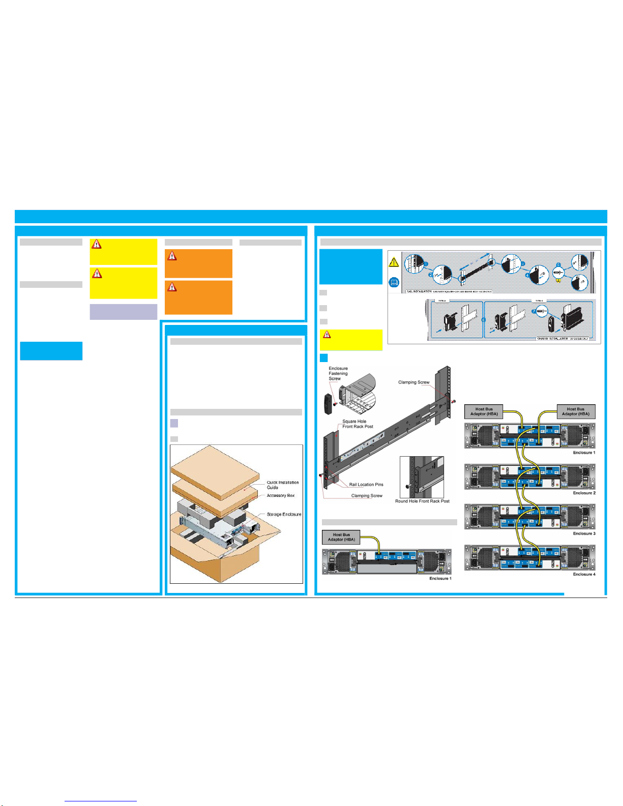
Slide the enclosure fully into the rack, and secure with screws in the mounting
flanges (see Figure
2).
•
The enclosure must only be operated
from a power supply input voltage
range of 100-240
VAC.
•
The plug on the power supply cord
is
used as the main disconnect
device.
Ensure that the socket outlets are located
near the equipment and are
easily
accessible.
•
When powered by multiple
AC
sources, disconnect all supply power for
complete
isolation.
•
In order to comply with
applicable
safety, emission and thermal
require-
ments no covers should be removed
and
all bays must be populated with
plug-in
modules.
•
The power connection should always
be disconnected prior to removal of
a
PCM from the
enclosure.
•
A safe electrical earth connection
must
be provided to the power supply
cords.
Check the grounding of the
enclosure
before applying
power.
•
Provide a suitable power source
with
electrical overload protection to meet
the
requirements laid down in the
technical
specification.
•
When bifurcated power cords
(‘Y’
leads) are used, they must only
be
connected to a supply range
of
200-240
V.
•
A faulty PCM must be replaced with a
fully operational module within 24
hrs.
•
Do not remove a faulty PCM
unless
you have a replacement model of
the
correct type ready for
insertion.
2.2 Unpacking the Storage System
Inspect the packaging for crushes, cuts, water damage or any other evidence of
mishandling during transit. If any damage appears present, for future reference
photograph the packaging before
opening.
Unpack the system. See Figure
1.
Figure
3:
Rack Mount Components
3.2
Connecting
to
Host:
Example
Configurations
Figure
4:
Single Host
-
Single Enclosure
Figure
5:
Dual Host
-
Multiple Enclosures
Figure
1:
Unpacking the Storage System
SBX24S QuickInstallation Guide
Important: The enclosure
MUST be grounded before
applying power.
Caution: A populated
enclosure can weigh up
to 24kg (53lb). Do not try to lift
it by yourself.
1.3 Rack System
Precautions
Warning: Do not
remove a PCM unless a
replacement can be immediately
added. The system must not be
run without all units or module
blanks in place.
Caution: The optional
RJ45 socket on the I/O
module, it isfor Ethernet
connection only and must
not be connected to a
telecommunications network.
Important: Thisrail kit must be
installed by trained service
personnel only. Before install-
ing this rail kit, ensure you
understand theseinstructions.
Ifin anydoubt please contact
your equipment supplier
.
Warning: Do not remove
covers from the PCM.
Danger of electric shock inside.
Return the PCM to your supplier
for repair.
Caution: If this equipment
is used in a manner not
specified by the manufacturer,
the protection provided by the
equipment may be impaired.
SBX24S Quick
Installation
Guide Version 2.0 | May 2011


