manuals.online logo
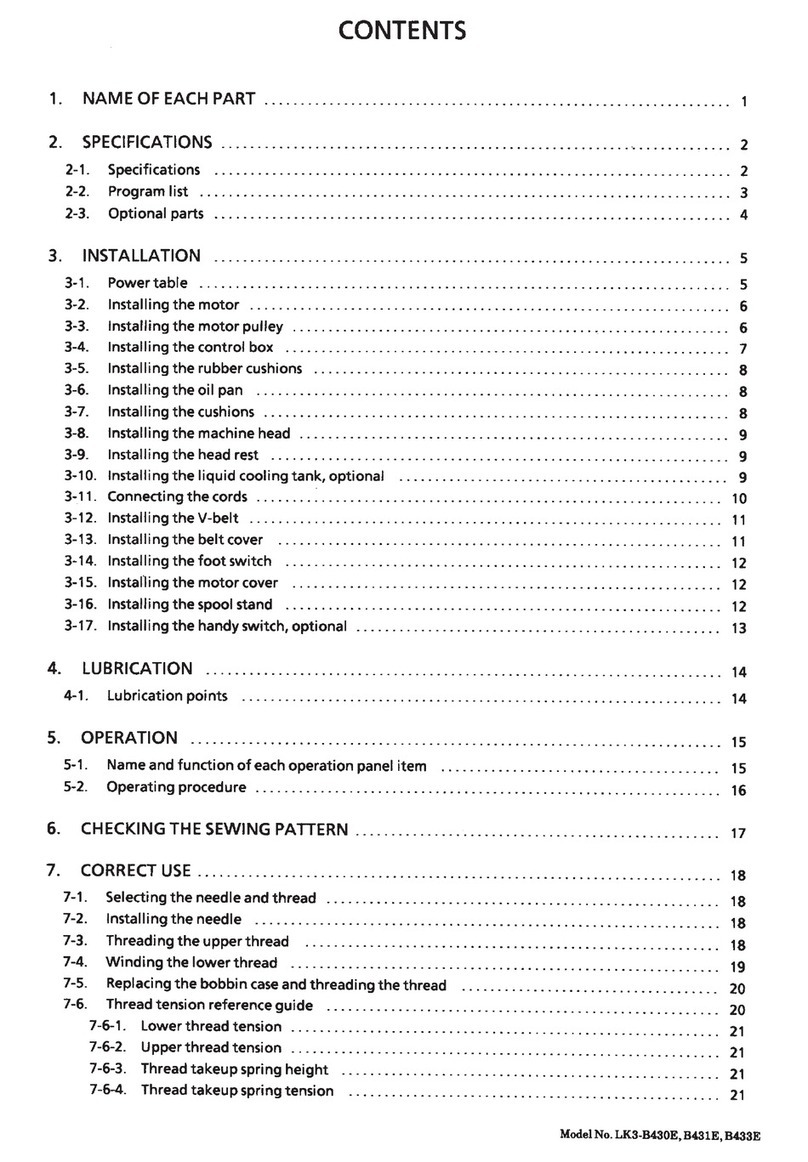
Brands
  1. Home
  2. •
  3. Brands
  4. •
  5. Brother
  6. •
  7. Sewing Machine
  8. •
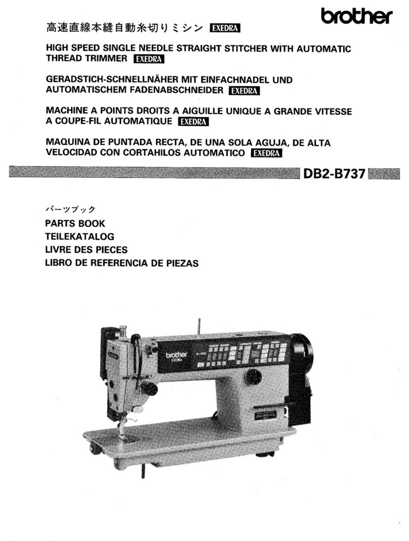
  9. Brother DB2-B793 User manual

Brother DB2-B793 User manual

Other Brother Sewing Machine manuals

Brother FD4-B271 User manual

Brother

Brother FD4-B271 User manual

Brother SA140 User manual

Brother

Brother SA140 User manual

Brother 882-W73 User manual

Brother

Brother 882-W73 User manual

Brother SCANNERII Troubleshooting guide

Brother

Brother SCANNERII Troubleshooting guide

Brother CE-8080PRW Setup guide

Brother

Brother CE-8080PRW Setup guide

Brother LS-1717 User manual

Brother

Brother LS-1717 User manual

Brother COMPACT OVERLOCK MACHINE User manual

Brother

Brother COMPACT OVERLOCK MACHINE User manual

Brother ELS Lettering User manual

Brother

Brother ELS Lettering User manual

Brother PC-850D User manual

Brother

Brother PC-850D User manual

Brother PR-620 User manual

Brother

Brother PR-620 User manual

Brother BAS-311E User manual

Brother

Brother BAS-311E User manual

Brother X L 2010 User manual

Brother

Brother X L 2010 User manual

Brother 882-D10 User manual

Brother

Brother 882-D10 User manual

Brother LZ2-B850 User manual

Brother

Brother LZ2-B850 User manual

Brother M945 Super ACE III User manual

Brother

Brother M945 Super ACE III User manual

Brother XL-2121 Mounting instructions

Brother

Brother XL-2121 Mounting instructions

Brother KE-430HX User manual

Brother

Brother KE-430HX User manual

Brother 888-P20 User manual

Brother

Brother 888-P20 User manual

Brother PR-600 User manual

Brother

Brother PR-600 User manual

Brother DH4-B981 User manual

Brother

Brother DH4-B981 User manual

Brother 888-F50 User manual

Brother

Brother 888-F50 User manual

Brother BAS-411 User manual

Brother

Brother BAS-411 User manual

Brother RH-981A User manual

Brother

Brother RH-981A User manual

Brother 888-F52 User manual

Brother

Brother 888-F52 User manual

Popular Sewing Machine manuals by other brands

Singer 569U1100 Operator's guide

Singer

Singer 569U1100 Operator's guide

ELNA 2002 instruction manual

ELNA

ELNA 2002 instruction manual

Siruba DL7200D-NM1 Instruction book

Siruba

Siruba DL7200D-NM1 Instruction book

Silver Viscount 9500e instruction manual

Silver

Silver Viscount 9500e instruction manual

Pfaff 3588-05/020 instruction manual

Pfaff

Pfaff 3588-05/020 instruction manual

JUKI DDL-9000A instruction manual

JUKI

JUKI DDL-9000A instruction manual

Pfaff 284 Instruction book

Pfaff

Pfaff 284 Instruction book

Reliable MSK-335B Specification sheet

Reliable

Reliable MSK-335B Specification sheet

Kenmore 385. 19000 owner's manual

Kenmore

Kenmore 385. 19000 owner's manual

Husqvarna Viking Designer SE user guide

Husqvarna Viking

Husqvarna Viking Designer SE user guide

Singer 645 owner's manual

Singer

Singer 645 owner's manual

Riccar RL634DE user manual

Riccar

Riccar RL634DE user manual

ZOJE ZJ9800 Operation manual

ZOJE

ZOJE ZJ9800 Operation manual

Siruba C007JP Instruction book

Siruba

Siruba C007JP Instruction book

IKEA SY user guide

IKEA

IKEA SY user guide

Pfaff 571 instruction manual

Pfaff

Pfaff 571 instruction manual

Singer 15-91 Adjusters manual

Singer

Singer 15-91 Adjusters manual

Pegasus WT100 Series instructions

Pegasus

Pegasus WT100 Series instructions

manuals.online logo
manuals.online logoBrands
  • About & Mission
  • Contact us
  • Privacy Policy
  • Terms and Conditions

Copyright 2025 Manuals.Online. All Rights Reserved.

INSTRUCTION
MANUAL
BEDIENUNGSANLEITUNG
MANUEL
D'INSTRUCTIONS
MANUAL
DE INSTRUCCIONES
._____
_
__
_
___
__
__
____J
082-8793
.___I
______,
SINGLE NEEDLE ADJUSTABLE
TOP
AND
BOTTOM
FEED
LOCK
STITCH
MACHINE
STEPPSTICH-N)lHMASCHINE
MIT
EINFACHNADEL UNO EINSTELLBAREM OBER-
UND UNTERTRANSPORT
MACHINE
A AIGUILLE UNIQUE A ENTRAINEMENT INFERIEUR ET SUPERIEUR
POUR SURFILAGE
MAQUINA
DE DOBLE PESPUNTE DE ALIMENTACION SUPERIOR E INFERIOR
AJUSTABLES
CON
UNA
SOLA
AGUJA
BROTHER INDUSTRIES, LTO.
NAGOYA
,
JAPAN
From the library of: Superior Sewing Machine & Supply LLC
Ill
Thank
you
very
much
for
your
purchase
of
a BROTHER sewing machine.
The
full
performance
of
your
new
sewing
machine
depends
, above all,
on
correct
ope
ration
.
Be sure
to
carefully read the foll
owing
instructions
before
use.
Ill Vielen Dank, daB Sie s
ich
fur
eine
BROT
HE
R-Na
hm
aschine
entschieden
haben.
Die
Leistungsfahigkeit
lhr
er
neuen
Nahmaschine
hangt
vor
all
em
von
de
r
richtigen
Bedienung
ab.
Lesen Sie
daher
bitte
vor
Gebrauch
diese
Bedienungsa
nl
eit
ung
sorgfaltig
durch
.
Ill
Nous
vo
us
remercions
d'avoir
achete
une
machine
a
co
udre
BROT:-lER.
Les
performances
de
votre
nouvelle
machine
a
coudre
dependent
, avant
tout
, de son utilisati
on
correcte
.
Lisez
attentivement
les
instructions
suivantes avant utilisation.
Ill
Muchas
gracias
por
haber
adquirido
una
maquina
de
coser
BROTHER.
El
buen
rendimiento
de
su nueva
maquina
de
coser
depende
sobre
todo
de
su
correcto
funcio
namient
o.
No
deje
de
leer
cuidadosamente
las
instrucciones
si
gu
ientes antes
de
comenzar
a usarla.
·
--
-0
I
.
~.
,
~
•
~
! e:;:3
..
-
,
...
<
Model
DB2-B
793-003>
0 Needle
bar
Nadelstange
Barre
aiguille
Barra
de
aguja
f)
Presser-regulation
thumb
screw
St
offd
r
ucke
rtuB-Reguliersch
ra
ube
Vis aoreille
du
regulateur
de pression
Tornillo
de
maripo
sa
para
regulaci6n
del
prensatelas
® BROTHER I
NDU
STRIES,
LTD.
082-8793-
r~~~r:::l[:::J
MADE
IN
JAPAN
c:r:c:.
~
Use
Verwendung
Utilisation
Uso
Sewi
ng
speed/Nahgeschwindigkeit
Vitesse de couture/Velocidad de costura
Maximum stitch length/ Max. Stichlange
0
f)
0
0
0
Thread
retainer
Fadendurchfuh
rung
Retenue
de
til
Retenedor del
hilo
0 Pre-tension
Vorspannung
Pretension
Tension prel
im
in
ar
1
-003
--
~-
0
I
..
<
Model
DB2-B793-015>
0 Pulley
Riemenscheibe
Poulie
Polea
0 Feed-reverse lever
Umkehrhebel
Lev
ier
d'inversion d'entra
ine
me
nt
Palanca
de
retroceso
de
Ia
a
limentaci6n
-015
F
or
medium materials Gathering
Mitteldicke Stoffe
Fa
ltennahen
Pour materiaux moye
ns
Fronce
Para
tejidos de grosor medio Fruncido
4,500 spm
Longue
ur
maximale
du
point/Longitud maxima de
Ia
puntada 5 mm
Maximum upper feed amount/Max. Obertransport
Quantile maximale de l'entrainement superieur/
Avance maximo de
Ia
alimentaci6n superior
6mm
8 mm
Presser foot heighVStoffdruckertuBhohe
Hauteur du presseur/Aitura del pie del prensatelas
6mm
Feed dog height!Transporteurhohe
Hauteur de
Ia
gr
iff
e d
'e
nt
rainemen
t/A
itura del alimentador 0.8 mm
Needle/Nadel DB X 1 #
11
Aiguille/Aguja
Use
gauge/Zubehor Group A/Satz A Group B/Satz B
Pieces calibrees/Piezas calibradas utilizadas Groupe A/Grupo A Groupe B/Grupo B
Shirring device/Kriiuselvorrichtung
~
lncluded/mitgeliefert
Att
achement
pour
fronces/Dispositivo para fruncido lnclus/lncluido
- 1-
From the library of: Superior Sewing Machine & Supply LLC
*If the
upper
feed
amount
is 6 mm
or
more,
or
if
the
lower
feed
amount
is4
mm
or more, u
se
a sewing speed less than 3500
spm
.
*Use a
maximum
feed amount
of
less than 6
mm
if
a stre
tc
hing (assembly A)
or
pucker-prevention (assembly C)
type
of
presser
foot/
feed dog assembly is used on model
082-8
793-015 (pedal system).
*Falls
der
Obertransport mehr als 6 mm
oder
der
Untertransport mehr als 4 mm betragt, dart die Nahgeschwindigkeit
3500 Stiche
pro
Minute
nicht
uberschreiten.
*Stellen Sie den Transport auf
nicht
mehr
als 6 mm ein, wenn beim Modell
082-8793-015
ein Transporteur bzw.
StoffdruckerfuB fUr dehnbare Stoffe (Vorrichtung A)
oder
zur
Verhutung von Fa
lt
enbildu
ng
(Vorrichtung C) verwendet
wird.
*Si l'entrainementsuperieur est de 6 mm
ou
plus et l'entrainement
inferieur
estde4 mm
ou
plus, utiliserune vitesse de
couture inferieure a3500 points
par
minute.
*Utiliser un entrainement maximum de
moins
de 6 mm en cas d'utilisation d'un ensemble pied presse
ur
/
griffe
d'entrainement de type tendeur
(e
nsemble A) ou de
type
anti-fronce (ensemble C) sur le modele
082-8793-015
(systeme apedale).
*
Si
el avance de Ia alimentaci6n
superior
es de 6 mm o mas, o si elavance de
Ia
alimentaci6n inferiores de 4 mm o mas,
utflizar
una
velocidad de
cost
ura
de
menos de 3500 ppm.
*Utilizar un avance de alimentaci6n m
aximo
de menos de 6 mm si
se
esta empleando un
tipo
de
conjunto
de
a
lim
entador/prensatelasde
tipo
tensor (conjunto A) o a
nt
ifruncido (conjun
to
C)
en
el modelo
082-8793-015
(s
istema
de pedal).
Table/Tisches/Table/
Me
sa
* Set the oil pan as above.
* Fit the head hinges0 in the table slot,
fit
it
to the
rubber
hinge
base 8
of
the table, and then place thehead
onto
the
rubber pads e at the f
our
corne
rs.
*When you use model
082-8793-015
(pedal system), please make a hole for chain as shown
on
the
figur
e above.
* Olwanne wie oben abgebildet stellen.
* D
ie
Scharniere0 in derTischaussparung einpassen, die Gummiauflagen 8 anbringen unddas Maschinenoberteila
uf
die
Dampier
f)
an allen vi
er
E
cken
stellen.
*
8eim
Modell
082-8793-015
(m
it
FuBpedal) muB ein Loch
fur
die Kette geboh
rt
werden (siehe
obige
Abbildung)
.
* Mettre Ia reservoir d'huile
com
me ci-dessus.
* Placer les rebords de Ia tete 0 dans
Ia
fente de
Ia
table,
Ia
placerdans
Ia
base de rebordde
caoutcho
uc
f)
de Ia table,
puis
placer
Ia
tete dans les patins de
caoutchouc
8
aux
quatre
coins.
• Quand on utili
se
le modele
082-8793-015
(systeme apedale), faire un trou
pour
Ia
chaine
com
me montre
sur
Ia
figure
ci-dessus.
* Coloque
Ia
charo
la del aceite
como
se indica arriba.
* Acoplar las bisagras0 de
Ia
cabeza en Ia ranura de Ia mesa, hacerlas
co
incidir
con
Iabase
decaucho8
de lasbisagras
en
Ia
mesa, y luego colocar Ia cabeza sobre las almohadillas de
caucho
f)
en las
cuat
ro esquinas.
*
AI
utilizar el modelo
08
2-8793-015 (sistema de pedal), perforar un
orificio
para
Ia
cadena, tal
como
se
indica
anteriormente.
-
2-
From the library of: Superior Sewing Machine & Supply LLC
========~
r
~=====
Shirring wire Installation (model
082-8793-015)
1. Install the sh
irring
wire 0
with
the step screw
f)
and
nut
0 to the s
hirring
wire lever 0 .
2.
Secure the shirring wire 0 with
se
t screw 0 and wire
ho
l
der
Q .
3.
Pass the shirring wire 0 through the hole in the table.
4. Secure the shirring wire 0 with set screw 8 and wire
holder
0 to the oil pan C).
5.
Secure the shirring wire 0 w
ith
step screw
~
·
6.
Lossen
nut
CD
an
d use the wire sleeve 0
to
remove
any
slack in the shirring wire 0 .
Ill Installation
for
pedal-
controlled
gather
sewing
1. H
ook
th
e
cha
in
Q)
to side 8
of
the knee l
ifter
stop.
2.
Tighten the
se
t screw
~
to
side A of the knee
lift
er s
top
.
*Note that the presser
foot
can still
be
raised by the knee
lifter
plate.
Ill Installation
for
knee
lifter
plate-controlled
gather
sewing
1. H
ook
the chain
4J)
to side A
of
the knee
lfit
er stop.
2.
Tight
en the set screw
40
to side 8
of
the knee
lifter
stop.
*Note that the presser foot can still be raised
with
the pedal.
*On models
D82-8793-
715 and 915,
connect
the chain
Q)
from the pedal
directly
to step screw
f)
.
8efestlgung des Krauselkabelzugs (Modell
082-8793
-015)
1.
Den Krauselkabelzug 0 mit de Schraube
f)
und
der
Mutter
0 am Krauselhebel befestigen 0 .
2.
Den Krauselkabelzug 0 mit dem Halter e und
der
Schraube 0 befestigen.
3.
Den Krauselkabelzug 0
durch
das
Loch
im Tisch ziehen.
4.
Den Krauselkabelzug 0 mit dem Halter 0 und der Schraube
f)
an
der
Olwanne C) befestigen.
5.
Den Krauselkabelzug 0 mit
der
Schraube
~
befestigen.
6.
Die
Mut
erG) losen und mit
der
Kabelmanschette
CD
eventuell vorhandenesSpiel des Krauselkabelzugs 0 ausgleichen.
Ill Vorbereitung fUr Kriiuselniihen mit Pedalbetatigung
1. Die Kette
Q)
an
der
Seite 8 des Kniehebelanschlags einhangen.
2.
Die Schraube
40
an
der
Seite A des Kniehebelanschlags festziehen.
* 8eachten Sie, daB
der
StoffdruckerfuB auch
durch
8etatigung
des Kniehebels hochgehoben werden kann.
Ill Vorbereitung
fur
Kriiuselnahen mit Kniehebelbetatigung
1. Die Kette
Q)
an
der
Seite A des Kniehebelanschlags einhangen.
2.
Die Schraube
~
an
der
Seite 8 des Kniehebelanschlags festziehen.
* Beachten Sie, daB StoffdruckerfuB
auch
durch
8etatigung
des FuBpedals
hochge
hoben werden kann.
)
r-
8efestigen Sie beim Modell D82-8793-715
und
915 die Kette
Q)
vom Pedal
direkt
an
der
Schraube
f)
.
Pose
du
cable de
fron~age
(modele
082-8793
-015)
1.
Monter
le cable
de
fr
ont;:age 0 avec
Ia
vis crantee
f)
et l'ecrou 0
au
levier de cable de front;:age o.
2. Fixer
le
cable de front;:age 0 avec Ia vis 0
et
le
support
de cable e.
3.
Faire passer le cable de front;:age 0
au
travers
du
trou
de
Ia
table.
4.
Fixer le cable de
fr
ont;:age 0 avec
Ia
vis 8 et le
suppo
rt de cable 0
au
reservoir d'huile
f)
.
5.
Fixer le
cab
le de fron
t;:age
0 avec Ia vis
crantee·
~
.
6.
Desserrer l'ecrou
CD
et
utiliser Ia gaine
du
cable 0
pour
supp
rim
er tout jeu du
cab
le de front;:age o.
Ill
Pose po
ur
front;:age
co
mmande a
Ia
pedale
1. Accrocher
Ia
chai
ne
Q)
sur
le cote 8 de
Ia
butee de genouillere.
2.
Serrer
Ia
vis de fixation
40
s
ur
le
cote
A
de
Ia butee de genouillere.
*Noter que le pied presseur peut etre encore soule
ve
par
le plateau de genouillere.
Ill
Pose
pour
le front;:age
commande
par Ia plaque de genouillere
1.
Accrocher
Ia
chaine
4J)
sur
le
cote
A de
Ia
butee de genouillere.
2. Serrer Ia vis de fixation
40
au
cote
8 de
Ia
butee de genouillere.
*
Noter
que le pied presseur
peut
etre encore souleve avec
Ia
pedale.
* Pour les model
es
D82-8793-715 et 915, raccorder Ia chaine
Q)
de
Ia
pedale directement a
Ia
vis
f)
.
lnstalacl6n del cable
de
fruncido (modelo
082-8793
-0
15)
1.
lnstalar el cable
de
fruncido
0
con
el
tornillo
escalonado
f)
y Ia tuerca 0 en Ia palanca del cable
de
fruncido
8 .
2. Asegurar el cable de fruncido 0
con
el
tornillo
de
fijacion
0 y el portador
de
cable e.
3. Pasar
el
cable de
fruncido
0 a traves del
orificio
en Ia mesa.
4. Asegurar el cable
de
fruncido
0 con el
tornillo
de fijaci6n 8 y el
portador
de cable 0 en Ia
ba
ndeja de aceite C).
5.
Asegurar el
cab
le de frun
cido
0
con
el
tornillo
escalonado
~
·
6.
Aflojar
Ia tuerca G) y utilizar el
manguito
del cable
CD
para elimin
ar
flojedades en el cable de
fr
u
ncido
0 .
Ill
lnstalacion para Ia
cos
tur
a de fruncidos con
control
por
pedal
1. Enganchar Ia cadena
Q)
al lado 8 del tope del levantador de rodilla.
2.
Apretar el tornillo de fijacion
40
al l
ado
A del tope del levantador de rodilla.
*
El
prensatelas aun puede
subir
con el levantador de rodill
a.
Ill
lnstalaci6n para
Ia
cos
tur
a de fruncidos con co
ntr
ol
por
levantador de rodilla
1. Enganchar Ia cadena
Q)
al lado A del tope del levantador de rodilla.
2.
Apretar el t
orni
llo
de
fijacion
~
al
lado 8 del tope del levantador de rodilla.
*
El
prensatelas aun puede
subir
con el pedal.
* En los modelos
D82-8793
-715 y 915, cone
ctar
Ia
cadena
Q)
del pedal directamente al tornillo escalonado
f)
.
-
3-
From the library of: Superior Sewing Machine & Supply LLC
Upper feed adjustment dial assembly
Oberetransporteinstellscheibe
Cadrans de reglage
de
l'entrainement superieur
Conjunto del dial
de
ajuste
de
Ia
alimentaci6n sperior
8
e
Knee lifter stop adjustment (for gather sewing)
*When the amount
of
material
lobe
gathered
or
shirred is changed,
be
s
ure
toadjust knee lifter stop B. Notethat
if
knee
lifter
stop
B is
not
properly
adjusted,thes
hirring
wire
will
wear
out
sooner
than
normal
,
or
the
gather
or
shirring
may be
too
small.
1. Set t
he
gather amount (on the
upper
feed scale).
2. Completely
lower
the gathersewing lever0 .Next, loosen the nut8
for
knee
lifter
stop
B,
and setthe stop 8
so
that
if
contacts the
oil
pan.
3. Be sure to
firmly
tighten
nut
8 when the adjustment is completed.
Einstellung des Kniehebelanschlags (fUr Krauselnahen)
*Falls die Kriiuselung geiindert wird, muB
der
Kniehebelanschlag B eingestellt werden. Bei falsch eingestelltem
Kniehebelanschlag B wird
der
Kriiuselkabelzug vorzeitig abgenutzt
und
die
Kriiuselung wird zu schwach.
1. Die Kriiuselung einstellen (auf
der
Obertransporteinstellscheibe).
2. Den Kriiuse
lh
ebel 0 ganznach unten stellen, die
Mutter
8
fur
den Kniehebelanschlag BIbsen undden Anschlag 8 so
einstellen,
daB
er
die Olwanne beruhrt.
3. Nach
der
Einstellung muB
die
Mutter
8
wieder
fest angezogen werden.
Reglage
de
butee de genouillere (pour
fron~age)
* Lorsque
Ia
quantile de tissu afroncer ou plisser est modifiee, ne pas oublierde regler
Ia
butee
de
genouillere
B.
Noterque
si
Ia
buteede
genouillere
B n'est pas correctement reglee, le cable de
fr
onc;ages'usera plusvilequenormalement,
ou
le
fronc;age sera
trop
s
err
e.
1. Regier Ia
qu
a
ntile
de france (sur
Ia
griffe
d'entrainement superieur
).
2. Abaissercompletement le levier de fronc;age 0 .Ensuite, desserrerl'ecrou8
pour
Iabutee degenouillere
B,
et
reglerIa
butee e de telle fac;on qu'elle
soil
en
contact
avec le reservoir d'huile.
3. Faire attention de serrer fermement l'ecrou 8 a
Ia
fin du reglage.
Ajuste del tope del levantador de rodilla (para
Ia
costura de fruncidos)
l:*
Cuando
se cambia
Ia
cantidad de tela a fruncir, ajustarel tope B
dellevantador
derodilla.
Sino
seajustacorrectame
nt
e
el tope B del levantador de rodilia, el cable de
fruncido
se
desgastara mas de
lo
normal, o el
fruncido
puede ser
muy
pequeno.
1. Fijar el espacio de
fruncido
(en
Ia
escala del
alimentador
s
up
erior).
2.
Bajar completamente
Ia
palanca del
frucido
0 . A
continuaci6
n aflojar
Ia
tuerca 8 para el tope B del levantador de
rodilla, y
colocar
el
tope e de tal forma que
entre
en
contacto
con
Ia
bandeja de aceite.
3.
Apretar
Ia
tuerca
f)
al completar el ajuste.
-4-
From the library of: Superior Sewing Machine & Supply LLC
[082-8793-003] [082-8793-015]
Knee lifter and knee lifter stop adjustment
* Using the stop screw
8,
adjust the gapbetween the push
bar&
and knee lifter(stop
A)
0
or
knee lifterto approx. 2
mm.
Next, using step screw
8.
adjustthegap between theknee lifter
Oand
oil
pan
so that
it
is
approx. 1mmwhen theknee
lift
plate is pressed.
Elnstellung des Knlehebels und des Knlehebelanschlags
* Mitder Anschlagschraube 8 den Zwischenraum zwischen der Stange8 und dem Kniehebelanschlag (A) 0 bzw. dem
Kniehebel aufca. 2
mm
einstellen. Oanach belgedrucktem Kniehebel mitder
Schraube8
den Zwischenraum zwischen
dem Kniehebel 0 und der Olwanne auf ca. 1
mm
einstellen.
R6glage de genoulllere et de butee de genoulllere
*
En
utilisant Ia vis de butee
e.
regler l'espace entre Ia barre de poussee 8 et
Ia
butee de genouillere (A) 0 ou Ia
genouillere a2 mm environ.
En
suite, al'alde de
Ia
vis crantee
8,
regler l'espace entre
Ia
genouillere0 et le reservoir
d'huile de telle faoon qu'il soit d'environ 1
mm
lorsque le plateau de genouillere est presse.
Ajuste del levantador y del tope del levantador de rodllla
* Usarel tornillodetope8 para ajustar
Ia
seperaci6nentreIa barrade
empuje8
yel tope
(A)
0 dellevantadorde rodiliao
el
levantador, aunos 2 mm. A continuaci6n utiIizar
el
tornillodefijaci6n8 para
aj
ustar
Ia
separaci6nentreellevantador
de rodilla 0 y
Ia
bandeja de aceite para que
sea
aproximadamente 1
mm
al apretar
Ia
placa dellevantador de rodilla.
Lubrication
Oiling
Anwendungsstelle
\..~;
Graissage
,.;
Engrase
o
1.
Slowly pour oil into the oil pan to the HIGH mark. If the oil level falls below the LOW mark, add oil.
2.
If the oil becomes contaminated, remove the oil cover screw
0.
3.
Wipe away contamination from the magnet
8.
and the oil pan.
*
Use
the oil specified
by
BROTHER: Hi-White
70.
Oiling
* Before using the machine,
be
sure to supply one
or
two drop
of
oil to the point indicated
by
the arrow.
Schmlerung
1.
Langsam
01
bis zur linken Markierung
(,HIGH")
einfUIIen. Wenn der Olstand unter die rechte Markierung (,LOW")
abfallt,
01
nachflillen.
2.
Wenn das
01
verschmutzt ist, die OlablaBschraube 0 entfernen.
3.
Den Schmutz vom Magneten
8und
der Olwanne entfernen.
* Das von BROTHER empfohlene WeiBol
70
verwenden.
Vor der lnbetrlebnahme
* Vor der lnbetriebnahme ein oder zwei Tropfen
01
an
der mit einem Pfeil bezeichneten Stelle auftragen.
Lubrlflcatlon
1.
Verser l'huile lentement jusqu'au repere "HIGH" situe agauche.
Si
le niveau d'huile tombe en-dessous du repere "LOW" situe adroite, ajouter de l'huile.
2.
Si
l'huile deviant sale, retirer
Ia
vis du carter d'huile
o.
3.
Retirer les dechets de l'aimant 8 et du carter d'huile.
* Utillser l'huile recommandee par BROTHER: Hi-white 70.
Gralssage
* Avant d'utiliser
Ia
machine, appliquer une ou deux gouttes d'huile au point indique par
Ia
fleche.
Lubrlcacl6n
1.
Echar aceite lentamente hasta alcanzar
Ia
marca ("HIGH") de
Ia
izquierda.
Si
el nivel del aceite baja
mas
alia de
Ia
marca ("LOW") de
Ia
derecha, agregar aceite.
2.
Si
el aceite
se
pone sucio, quitar
el
tornillo de
Ia
cubierta de aceite
0.
3.
Limpiar Ia suciedad
en
los imanes
8.
yen
Ia
charola de aceite.
* Usar el aceite especificado BROTHER: Hi-White
70.
Eng
rase
* Antes de usar Ia maquina, asegurarse de echar una o dos gotas de aceite en el punto indicado por
Ia
flecha.
-5-
From the library of: Superior Sewing Machine & Supply LLC
Less
oil
weniger
01
More oil
mehr
01
Less
oil
weniger
01
Moins d'huile
Menos aceite
®
Less
oil
weniger
01
More oil
Moins d'huile mehr
01
aceite Plus d'huile
Plus d'huile
~~asaceite
~
'0
•
M&saceite~
Armshaft and hook lubrication
* Remove theface plate, and then turn theoiladjusting
screwO
to
adjustthe
flow
of
lubricationoil.
Tilt
themachinehead,
and turn the screw
f)
to
adjust the
oil
flow
to
the rotary hook.
Schmierung der FOhrungswelle und des Grelfers
* Urn
die
erforderliche Menge Schmierol einzustellen, die Vorderplatte abnehmen
und
die Regulierschraube0
fur
die
Schmierung
der
Fuhrungswelle drehen. Urn die erforderliche Menge
01
fur
den Greifer einzustellen, das
Maschinenoberteil umkippen und
die
Regulierschraube
f)
fUr die Schmierung des Greifers drehen.
Lubrificatlon de l'axe du bras et du crochet
* Enlever Ia plaque avant.
Tourner
Ia vis 0 de reglage
d'huile
de l'axe
du
bras afin
de
regler
le
debit
de l'huile
de
lubrification. Incliner Ia tete de Ia machine.
Tourner
Ia vis
f)
de reglage d'huile
du
crochet
rotatifafin
de
reglerle
debit
d'huile au crochet rotatif.
Lubricaclon del eje del brazo y del cangrejo
* Sacar
Ia
placa delantera haciendo luego
girar
el
tornillo
de
control
del aceite 0 para regular debidamenteel
flujo
del
aceite lubricante. Inclinar
Ia
parte
de
arriba
de
Ia maqulnay hacergirarel
tornillo
f)
para regulardebidamente
el
flujo
de
aceite hacia el cangrejo.
About
15
"'
20mm
ungefahr
15"'
20mm
Erviron
15
a
20mm
Unos
15"'
20mm
Sens de rotation de
Ia
machine
Rotation direction
of
the machine
*
The
correct rotating direction
of
the machine is counter-
clockwise as viewed from the pulley side.
* Press the
belt
0.
and adjust the belt tension by
turning
the
nut
f)
so that
the
belt can be pushed inward about 15
,...,
20
mm.
*When the machineurns idle, be sure
to
raisethapresserfoot.
Drehrlchtung der Nihmaschine
* Die richtige Drehrichtung
der
Maschine ist von
der
Riemenscheibe aus gesehen nach links.
* Den Riemen 0 durchdrucken und die Riemenspannung
durch
Drehen
der
Mutter
f)
so einstellen, daB
der
Riemen
15,...,
20
mm durchhangt.
*Wenn die Maschine leer dreht, den StoffdruckerfuB
hochstellen.
* Le sens
de
rotation correct de
Ia
machine est dans.le sens inversedes aiguillesd'une montrelorsqu'on regarde
du
cOte
de
Ia
poulie.
* Appuyer
sur
Ia
courroie
0.
et
regler
Ia
tension
de
Ia
courroieen tournant l'ecrou
f)
defaconque
Ia
courroiepuisseetre
poussee de
15,...,
20 mm vers l'interieur.
* Lorsque Ia machine tourne au ralenti,
toujours
lever le presseur.
Sentido de rotaclon de
Ia
maqulna
*
El
sentido correcto de rotaci6n de Ia maquina es hacia
Ia
izquierda, vista desde
ellado
de Ia polea.
* Presionar Ia correa
0.
y ajustar Ia tension de Ia correa haciendo
girar
Ia tuerca 8 de tal forma que Ia correa pueda
empujarse hacia adentro entre 15 y
20
mm.
* Cuando
Ia
maquina esta funcionado en vacio, asegurarse de que el pie del prensatelas esta levantado.
-6-
From the library of: Superior Sewing Machine & Supply LLC
Precautions before Installing the belt cover:
1.
Fitthe
V belt onto the sewing machine pulley.
2.
Bring the sewing machine down toward the horizontal position, and then install the belt cover.
3.
The set screws
for
belt cover instalation are in the accessories pocket.
Vorkehrungen vor dem Anbrlngen des Rlemenschutzes
1.
Den Keilriemen
an
der Motorriemenscheibe anbringen.
2.
Die Nahmaschine in die Horizontalstellung umklappen und den Riemenschutz montieren.
3.
Die Schrauben fur den Riemenschutz befinden sich in der Zubehortasche
Precautions aprendre avant de monter le couvercle de courroie:
1.
Monter
Ia
courroie trapezo"idale sur Ia poulie de Ia machine.
2.
Descendre
Ia
machine vers
Ia
position horizontale, puis monter le couvercle de courroie.
3.
Les
vis
de
montage pour
Ia
pose du couvercle de courroie
se
trouvent dans
Ia
pochette des accessoires.
Precauclones a tomar antes de lnstalar
Ia
cublerta de
Ia
correa:
1.
Colocar
Ia
correa trapezoidal en
Ia
polea de
Ia
maquina de coser.
2.
Bajar
Ia
maquina a
su
posici6n horizontal normal, e instalar
Ia
cubierta de
Ia
correa.
3.
Los tornillos
de
fijaci6n para
Ia
instalaci6n de
Ia
cubierta de
Ia
correa
se
encuentran
en
Ia
bolsa de accesorios.
1.
Screw the white stud 0 into the machine head.
2.
Temporarily tighten screw A0 and the spring washer
8to
the white stud.
3.
Install belt cover U8 with screw A0
as
shown in the figure at the up.
4.
Install belt cover U8 with screw B8 and the spring washer e.
'*
When installing belt cover U e. please bring down the machine.
5.
Install belt cover D 8 with screws 8 and washers
C).
'*
When
installing belt cover D
0.
please set up the machine.
* When replacing the V belt, remove belt cover U
8.
1.
Schrauben Sie die weiBe Stiftschraube 0 in das Maschinenoberteil.
2.
Den Federring 8 einsetzen und die Schraube A0 provisorisch
an
der weiBen Stiftschraube festziehen.
3.
Befestigen Sie den Riemenschutz U 8 mit der Schraube A0 wie oben abgebildet.
4.
Befestigen Sie den Riemenschutz U 8 mit der Schraube B 8··und·dem Federring e.
* Zum Befestigen des Riemenschutzes U 8
muB
die Maschine heruntergeklappt werden.
5.
Den Riemenschutz D 0 mit
der
Schraube 8 und dem Federring 8 befestigen.
'*
Zum Befestigen des Riemenschutzes D 8
muB
die Maschine hochgeklappt warden.
'*
Zum Auswechseln des Riemens
muB
der Riemenschutz U 8 entfernt werden.
1.
Visser l'ergot blanc 0 sur
Ia
t6te de
Ia
machine.
2.
Visser provisoirement
Ia
vis A 0 et
Ia
rondelle Grower 8 al'ergot blanc.
3.
Monter le couvercle
de
courroie U8 avec
Ia
vis A 0 comme indique sur
Ia
figure ci-clessus.
4.
Monter le couvercle
de
courroie U8 avec
Ia
vis B8 et
Ia
rondelle Grower
0.
* Lors de
Ia
pose du couvercle de courroie U
8,
abaisser
Ia
machine.
5.
Monter
le
couvercle
de
courroie D8 avec les vis 8 et
les
rondelles
f).
* Lors de
Ia
pose du couvercle de courroie D
0.
lever
Ia
machine.
'*
Lors du remplacement
de
Ia
courroie trapezo"idale, retirer le couvercle de courroie U
8.
1.
Atornillar
el
pasador blanco 0
en
Ia
cabeza de
Ia
maquina.
2.
Apretar provisoriamente el tornillo A 0 y
Ia
arandela de resorte 8
en
el
pasador blanco.
3.
lnstalar Ia cubierta U de
Ia
correa 8 con
el
tornillo A 0 tal como aparece en
Ia
figura anterior.
4.
lnstalar
Ia
cublerta U de
Ia
cor
rea
8 con el tornillo B 8 y
Ia
arandela de resorte
0.
* Para instalar
Ia
cubierta U de
Ia
correa e. bajar
Ia
maquina.
5.
lnstalar
Ia
cubierta D
de
Ia
correa 8 con los tornillos 8 y
las
arandelas
8.
'*
Para instalar
Ia
cublerta D
de
Ia
correa e. levantar
Ia
maquina.
*
Para
cambiar
Ia
correa, quitar
Ia
cubierta U de
Ia
correa
8.
-7-
From the library of: Superior Sewing Machine & Supply LLC
Installation du bobineur
* Installer
Ia
bobineur 0 sur
Ia
table avec 2 vis
8.
How to install the bobbin winder
* Install the bobbin winder0 tothetablewith twoscrews
e.
(Install it so that the bobbin winder pulley 8 wil
not
slip.)
Montage des Spulers
*
Den
SpulerO
mltzwei
Schrauben8
am Tisch befestigen.
(Die Spulerscheibe 8 darf nicht rutschen.)
(L'installer de
fac;on
que
Ia
poulie du bobineur 8
ne
glisse pas.)
C6mo instalar
Ia
canillera
* lnstalar
Ia
canillera 0
en
Ia
mesa mediante dos tornillos
e.
(lnstalarla de forma que
Ia
polea de
Ia
canillera 8 no
se
deslice.)
0 • •
How to remove the bobbin case
1.
Raise the needle above the needle plate.
2.
After lifting the latch
of
the bobbin case
0,
remove the bobbin case.
3.
The bobbin 8 will come out when the latch is released.
4.
Bobbin case 0 installation is the reverse of removal order.
*
Be
sure to place the bobbin case seat8 inside the bobbin case. Alsoabobbinspring8 is included onautomaticthread
trimming machines.
Entnahme der Spulenkapsel
1.
Die Nadel hochstellen,
so
daB
sie
Ober
der Stichplatte steht.
2.
Die
Lasche der Spulenkapsel 0 hochziehen und die Spulenkapsel herausnehmen.
3.
Wenn die Lasche gelost wird, fallt die Spule 8 heraus.
4.
Das
Einsetzen der Spulenkapsel 0 erfolgt in umgekehrter Reihenfolge des Herausnehmens.
* Dar Spulenkapselsitz 8
muB
in die Spulenkapsel eingesetzt werden.
Bel
Maschinen mit automatischem
Fadenabschneider ist eine Spulenfeder 8 vorhanden.
Retralt de
Ia
boite acanette
1.
Lever l'aiguille au-dessus de
Ia
plaque aaiguille.
2.
Retirer
Ia
boite acanette apres avoir souleve son loquet
0.
3.
La
canette 8 sort lorsque le loquet est relache.
4.
Pour
Ia
mise en place du boitier de
Ia
canette
0.
proceder com
me
pour le retrait du boitier de la.canette, mais dans
l'ordre inverse.
~ Veilleraplacerlesiegedu
boitierdecanettef)
al'interieurduboitierdelacanette.Un
ressortdecanettee
estlnclussur
les machines avec coupure de fil automatique.
C6mo qultar
Ia
caja de
Ia
canilla
1.
Levantar
Ia
aguja por encima de
Ia
placa de aguja.
2.
Luego de levantar
Ia
traba de
Ia
caja de
Ia
canilla
0.
quitar
Ia
caja de
Ia
canilla.
3.
La
canilla 8 saldra
al
liberar
Ia
traba.
4.
El
orden de instalaci6n de
Ia
caja de
Ia
canilla 0
es
el inverso al de desmontaje.
~
Verificarque
se
haya colocado el asiento deIa caja de
Ia
canilia8 dentrode
Ia
cajade
Ia
canilia. Tambien
se
haincluido
un
resorte de bobina 8 en las maquinas de coser con cortahilos automatico.
-8-
From the library of: Superior Sewing Machine & Supply LLC
Aufwlckeln des Unterfadens
1.
Die Spule 0 auf die
Spulerspindel8
stecken.
•
•
Lower thread winding
1.
Fit the bobbin 0 onto the bobbin winder spindle
8.
2.
Push
the bobbin winderstop latch 8 completely upward.
3.
After winding the thread around the bobbin0 afewtimes
in the direction
of
the arrow, operate the machine.
4.
If the thread cannot
be
wound evenly, adjust the bobbin
winder tension bracket 8 by moving
it
to the left
or
right
after loosening the set screw
8.
* To wind more thread on the bobbin
0.
tighten the
adjustment screw
e.
2.
Den
Spulerhebel 0 ganz nach oben drucken.
3.
Den
Faden
einige Male in Pfeilrichtung
urn
die Spule 0 wickeln und die Nahmaschine betatigen.
4.
Wenn
der
Faden
nichtgleichmaBigaufgewickeltwerden kann, dieStellschraube
Glosen
und den Spulerspannhalter8
nach links oder rechts verschieben.
*
Urn
mehr Faden auf die Spule 0
zu
wickeln, die Schraube 8 anziehen.
Boblnage du fll lnferleur
1.
Placer
Ia
canette 0 sur
Ia
broche du bobineur e.
2.
Pousser le loquet d'arret du bobineur 8 completement vers le haut.
3.
Faire fonctionner
Ia
machine apres avoir enroule
le
fil plusieur fois autour de
Ia
canette 0 dans le
sens
de
Ia
fleche.
4.
Si
le fil
ne
peut pas etre enroule de faoon reguliere, regler
le
support de tension du bobineur8
en
le deplaoant vers
Ia
gauche ou
Ia
droite apres avoir desserre
Ia
vis d'arret
8.
* Pour enrouler plus
de
til sur
Ia
canette
0.
serrer
Ia
vis de reglage e.
Boblnado de hllo Inferior
1.
Colocar
Ia
canilla 0
en
el
huso
de
Ia
canillera e.
2.
Tirar de
Ia
traba de tope de
Ia
canillera 8 completamente hacia arriba.
3.
Luego
de
enrollarel hilo alrededor
de
Ia
canilia0 varias vueltas
en
el
sentido indicado
porIa
flecha, hacerfuncionar
Ia
maquina.
4.
Si
el hilo
no
queda bobinado
de
forma pareja, ajustar
Ia
mensula 8 para
Ia
tension de
Ia
canillera moviendo
Ia
misma
hacia
Ia
derecha y hacia
Ia
izquierda luego de aflojar
el
tornillo de fijaci6n e.
*
Para
bobinar
mas
hilo
en
Ia
canilia
0.
apretar
el
tornillo de ajuste
8.
FadenfOhrung In der Spulenkapsel
1.
Die Spule in die Spulenkapsel stecken.
Threading the bobbin case
1.
Insert the bobbin into the bobbin
case.
2.
Pass
.the thread through the slot 0 and under the lower
thread adjustment spring e.
3.
Pull the thread through delivery eye 8 at one end of the
lower thread adjustment spring e.
4.
Holding the bobbin case latch, insert the bobbin case into
the rotary hook.
2.
Den
Faden
durch den Schlitz 0 und unter die Unterfaden-Einstellfeder 8 ziehen.
3.
Den
Faden
durch das Zufuhrloch 8
am
Ende der Unterfaden-Einstellfeder8 ziehen.
4.
Die Sperrlasche halten und die Spulenkapsel in den Greifer einsetzen.
Enfllage du bottler de
Ia
canette
1.
Mettre
Ia
canette dans le boitier
de
Ia
canette.
2.
Passer
le
fil dans
Ia
fente 0 et so
us
le
ressort
de
reglage du.filinferieur e.
3.
Tirer le fil·par1e chas de passage 8 al'une des extremites du ressort de reglage du fil inferieur e.
4.
Tenir
le
boitier de
Ia
canette par
Je
clip et introduire le boitier dans le crochet rotatif.
Enhebrado de
Ia
caja de Ia canllla
1.
Meter
Ia
bobina
en
Ia
caja de
Ia
canilla.
2.
Pasar
el
hilo por
Ia
ranura 0 y por debajo del resorte de ajuste del hilo inferior e.
3.
Tirar
el
hilo a traves del ojo
de
entrega 8
en
una
de las puntas del resorte de ajuste del hilo inferior e.
4.
Sostener
el
pestillo
de
Ia
caja de
Ia
canilla e introducir
Ia
caja de
Ia
canilia
en
el
cangrejo.
-9-
From the library of: Superior Sewing Machine & Supply LLC