manuals.online logo
Brands
  1. Home
  2. •
  3. Brands
  4. •
  5. Bryant
  6. •
  7. Air Conditioner
  8. •
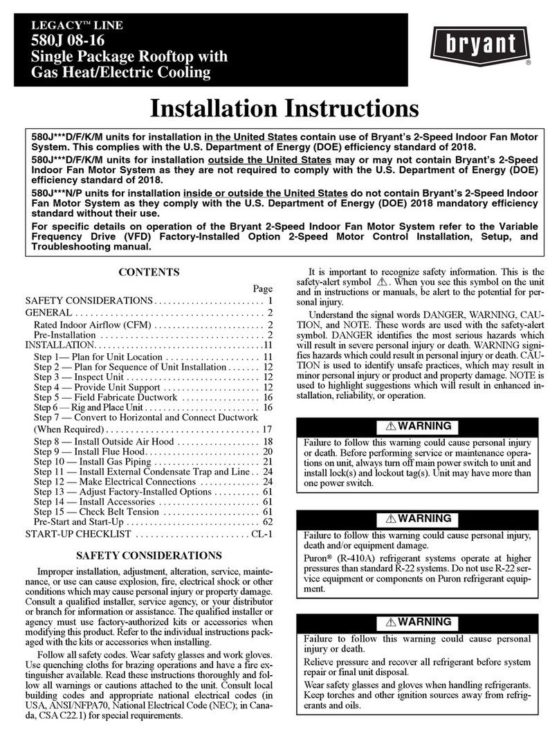
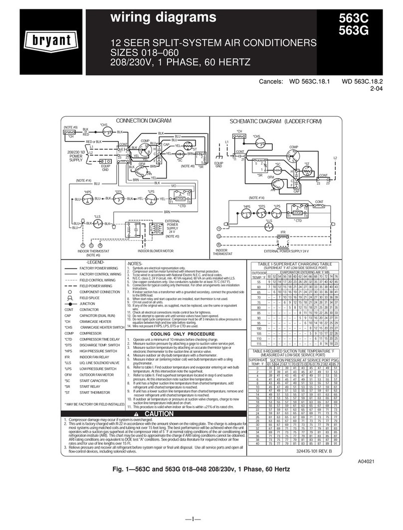
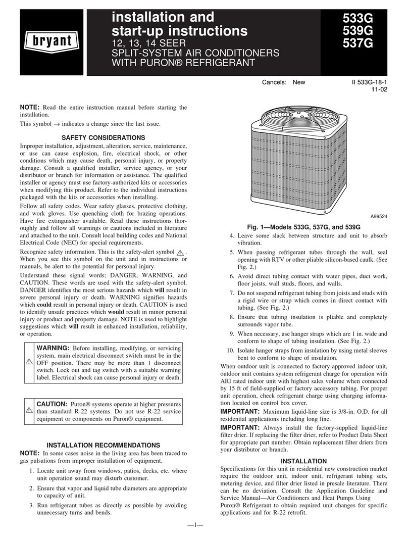
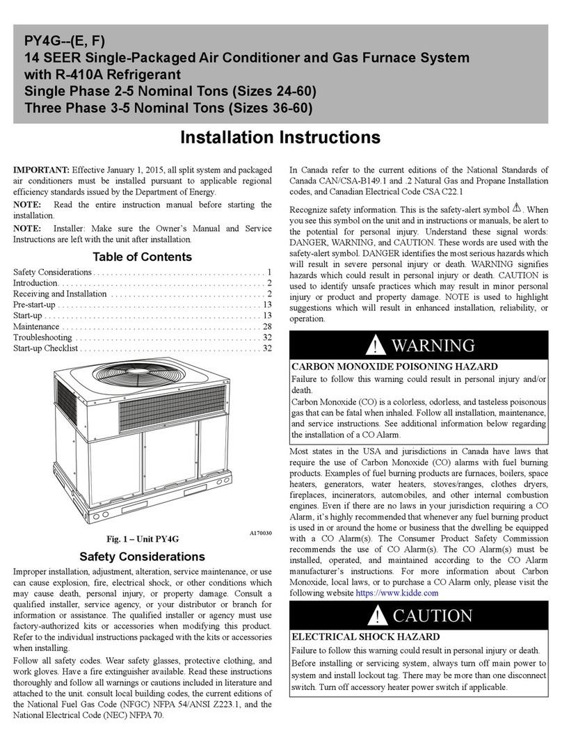
  9. Bryant 14 SEER User manual

Bryant 14 SEER User manual

Service Manual
14 and 15 SEER Small Package Products
Air Conditioners and Heat Pumps
Using R---410A Refrigerant
TABLE OF CONTENTS
PAGE
SAFETY CONSIDERATIONS 2.........................
INTRODUCTION 2...................................
INSTALLATION GUIDELINE 2........................
ACCESSORIES 3.....................................
LOW--AMBIENT COOLING GUIDELINE 4...............
ELECTRICAL 6--7....................................
Aluminum Wire 6..................................
Contactor 6.......................................
Capacitor 6.......................................
Cycle Protector 7...................................
Crankcase Heater 7.................................
PRESSURE SWITCHES 7..............................
Low--Pressure Switch 7...........................
High--Pressure Switch (AC & HP) 7.................
DEFROST THERMOSTAT 8...........................
DEFROST CONTROL BOARD 8--8......................
Defrost Control 8...............................
COPELAND SCROLL, DANFOSS SCROLL ,
LG SCROLL 10--11...................................
Compressor Failures 11..............................
Mechanical Failures 11..............................
Electrical Failures 11................................
RECIPROCATING COMPRESSOR 13...................
FAN MOTOR 13......................................
COMPRESSOR PLUG 13..............................
LOW--VOLTAGE TERMINALS 13.......................
REFRIGERATION SYSTEM 14--17......................
Refrigerant 14.....................................
Compressor Oil 14..................................
Brazing 15........................................
Liquid Line Filter Drier 16...........................
Suction Line Filter Drier 16...........................
Accumulator 16....................................
Thermostatic Expansion Valve (TXV) 17................
PISTON BODY CLEANING OR REPLACEMENT 18.......
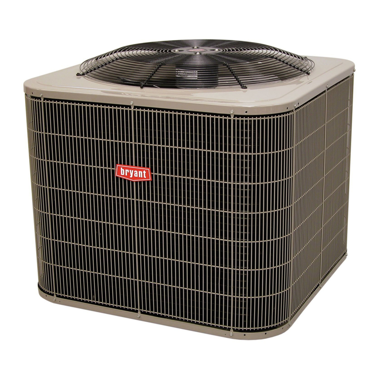
14 SEER A/C & Heat Pump
A09034
15 SEER A/C & Heat Pump
A09033
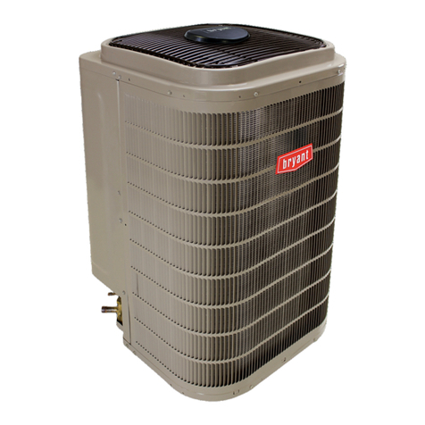
Fig. 1 – A/C and Heat Pump
PAGE
REFRIGERATION SYSTEM REPAIR 18..................
Leak Detection 18..................................
Coil Removal 19...................................
Compressor Removal and Replacement 19...............
System Clean--Up After Burnout 19....................
Evacuation 20.....................................
2
CHECK CHARGE 20..................................
TROUBLESHOOTING WITH SUPERHEAT 21.............
INDOOR AIRFLOW AND AIRFLOW ADJUSTMENTS 22--27
Refrigerant 22.....................................
Heating Check Charge Procedure 22....................
Sequence of Operation 27............................
ECM FAN MOTOR TROUBLESHOOTING 27--29..........
Time Delays 27....................................
Pressure Switches 28................................
Accumulator, Reversing Valve (RVS) 28.................
Control Box 29....................................
SINGLE STAGE 30...................................
TWO STAGE 35......................................
CARE AND MAINTENANCE 41........................
R--410A QUICK REFERENCE GUIDE 42.................
INDEX OF TABLES 47................................
My Learning Center is your central location for professional
residential HVAC training resources that help strengthen careers
and businesses. We believe in providing high quality learning
experiences both online and in the classroom.
Please contact us at mylearning@utc.com with questions regarding
access to My Learning Center.
SAFETY CONSIDERATIONS
Installation, service, and repair of these units should be attempted
only by trained service technicians familiar with standard service
instruction and training material.
All equipment should be installed in accordance with accepted
practices and unit Installation Instructions, and in compliance with
all national and local codes. Power should be turned off when
servicing or repairing electrical components. Extreme caution
should be observed when troubleshooting electrical components
with power on. Observe all warning notices posted on equipment
and in instructions or manuals.
UNIT OPERATION AND SAFETY HAZARD
Failure to follow this warning could result in personal
injury or equipment damage.
R--410A systems operate at higher pressures than standard
R--22 systems. Do not use R--22 service equipment or
components on these R--410A units. Ensure service
equipment is rated for R--410A.
!WARNING
CUT HAZARD
Failure to follow this caution may result in personal injury.
When removing access panels (see Fig. 17) or performing
maintenance functions inside your unit, be aware of sharp
sheet metal parts and screws. Although special care is taken
to reduce sharp edges to a minimum, be extremely careful
and wear appropriate clothing, safety glasses and gloves
when handling parts or reaching into the unit.
!CAUTION
Refrigeration systems contain refrigerant under pressure. Extreme
caution should be observed when handling refrigerants. Wear
safety glasses and gloves to prevent personal injury. During normal
system operations, some components are hot and can cause burns.
Rotating fan blades can cause personal injury. Appropriate safety
considerations are posted throughout this manual where potentially
dangerous techniques are addressed.
Follow all safety codes. Wear safety glasses, protective clothing,
and work gloves. Have a fire extinguisher available. Read these
instructions thoroughly and follow all warnings or cautions
included in literature and attached to the unit. Consult local
building codes, the current editions of the National Electrical Code
(NEC) NFPA 70 and NFPA 90B--Installation Warm Air Heating
and A/C Systems (Residential).
In Canada refer to the current editions of the Canadian Electrical
Code CSA C22.1.
INTRODUCTION
This document provides required system information necessary to
install, service, repair or maintain the small package products (SPP)
air conditioners and heat pumps using R--410A refrigerant.
Refer to the unit Product Data/Technical specifications for rating
information, electrical data, required clearances, additional
component part numbers and related pre--sale data. Installation
Instructions are also available per specific models.
Information in this document refers to units produced in 2015 to
current.
INSTALLATION GUIDELINE
New Construction
Specifications for these units in the new construction market
require the unit to be installed outdoors and meet all local code and
requirements. Consult the Installation Instructions for any
additional installation detail.
Add--On Replacement (Retrofit)
Specifications for these units in the add--on replacement/retrofit
market require the unit to be installed outdoors and meet all local
codes and requirements. Clearances, power supply, system static
needs to be check to ensure that the replacement unit can perform
within the design parameter desired specified in the Product Data.
15
Table 3—Compressor Information
14 SEER Air Conditioner
Unit Size 24 30 30 36 42 48 60
Type AC AC AC AC AC AC AC
Chassis Size Small Small Small Small Large Large Large
Compressor Rotary Recip Scroll
Manufacturer Oil Type PVE Hatcol 32BCE
Polyolester (POE) 3MAF Polyolester Oil (POE)
Oil Charge --- fl.oz. (intial/recharge) 27/24 30 / 27 25/21 .80 42/36 42/36 42/36
W i n d i n g R e s i s t a n c e --- o h m ( S t a r t C --- R ) 5.01 0.98 .89 0.89 0.61 0.50 0.42
W i n d i n g R e s i s t a n c e --- o h m ( S t a r t C --- S ) 3.51 1.73 1.02 1.66 1.63 0.81 0.93
W i n d i n g R e s i s t a n c e --- o h m ( S t a r t R --- S ) 8.52 2.71 191 2.55 2.23 1.31 1.35
Run Capacitor (mfd / volts) 40 / 440 40 / 440 35/370 45 / 440 45 / 440 70 / 440 70 / 440
15 SEER Air Conditioner
Unit Size 24 30 36 42 48 60
Type AC AC AC AC AC AC
Chassis Size Small Small Large Large Large Large
Compressor Scroll
Manufacturer Oil Type 3MAF Polyolester Oil (POE)
Oil Charge --- fl.oz. (intial/recharge) 25/21 25/21 40/370 42/38 42/38 42/38
W i n d i n g R e s i s t a n c e --- o h m ( S t a r t C --- R ) 1.30 1.02 0.85 0.62 0.53 0.42
W i n d i n g R e s i s t a n c e --- o h m ( S t a r t C --- S ) 1.64 1.91 1.50 1.55 1.9 1.67
W i n d i n g R e s i s t a n c e --- o h m ( S t a r t R --- S ) 2.94 2.93 2.35 2.17 2.44 2.09
Run Capacitor (mfd / volts) 35 / 370 40/370 40/370 45 / 370 30/370 40/370
14 SEER Heat Pump
Unit Size 24 30 36 42 48 60
Type HP HP HP HP HP HP
Chassis Size Small Small Large Large Large Large
Compressor Scroll
Manufacturer Oil Type 3MAF Polyolester Oil (POE)
Oil Charge -- fl.oz. (intial/recharge) 25/19 25/21 25/19 43/38 42/36 42/36
Winding Resistance --ohm (Start C--R) 1.30 1.02 0.89 0.56 0.50 0.41
Winding Resistance --ohm (Start C--S) 1.64 1.91 1.66 1.31 0.81 0.76
Winding Resistance --ohm (Start R--S) 2.94 2.93 2.55 1.86 1.31 1.16
Run Capacitor (mfd / volts) 35 / 440 40/440 45 / 440 45 / 440 70 / 440 70 / 440
15 SEER Heat Pump
Unit Size 24 30 36 42 48 60
Type HP HP HP HP HP HP
Chassis Size Small Small Large Large Large Large
Compressor Scroll
Manufacturer Oil Type 3MAF Polyolester Oil (POE)
O i l C h a r g e --- f l . o z . ( i n t i a l / r e c h a r g e ) 25/21 25/21 40/370 42/38 42/38 42/38
W i n d i n g R e s i s t a n c e --- o h m ( S t a r t C --- R ) 1.30 1.02 0.85 0.62 0.53 0.42
W i n d i n g R e s i s t a n c e --- o h m ( S t a r t C --- S ) 1.64 1.91 1.50 1.55 1.90 1.67
W i n d i n g R e s i s t a n c e --- o h m ( S t a r t R --- S ) 2.94 2.93 2.35 2.17 2.44 2.09
Run Capacitor (mfd / volts) 35 / 370 40/370 40/370 45 / 370 30/370 40/370
Brazing
This section on brazing is not intended to teach a technician how to
braze. There are books and classes which teach and refine brazing
techniques. The basic points below are listed only as a reminder.
Definition: The joining and sealing of metals using a nonferrous
metal having a melting point over 800_F/426.6_C.
Flux: A cleaning solution applied to tubing or wire before it is
brazed. Flux improves the strength of the brazed connection.
When brazing is required in the refrigeration system, certain basics
should be remembered. The following are a few of the basic rules.
1. Clean joints make the best joints. To clean:
Remove all oxidation from surfaces to a shiny
finish before brazing.
Remove all flux residue with brush and water while
material is still hot.
2. Silver brazing alloy is used on copper--to--brass,
copper--to--steel, or copper--to--copper. Flux is required
when using silver brazing alloy. Do not use low temperature
solder.
3. Fluxes should be used carefully. Avoid excessive
application and do not allow fluxes to enter into the system.
4. Brazing temperature of copper is proper when it is heated to
a minimum temperature of 800_F (426.6_C) and it is a dull
red color in appearance.
Reversing Valve
In heat pumps, changeover between heating and cooling modes is
accomplished with a valve that reverses flow of refrigerant in
system. This reversing valve device is easy to troubleshoot and
replace. The reversing valve solenoid can be checked with power
off with an ohmmeter. Check for continuity and shorting to
ground. With control circuit (24v) power on, check for correct
voltage at solenoid coil. Check for overheated solenoid.
With unit operating, other items can be checked, such as frost or
condensate water on refrigerant tubes.
16
The sound made by a reversing valve as it begins or ends defrost is
a “whooshing” sound, as the valve reverses and pressures in system
equalize. An experienced service technician detects this sound and
uses it as a valuable troubleshooting tool.
Using a remote measuring device, check inlet and outlet line
temperatures. DO NOT touch lines. If reversing valve is operating
normally, inlet and outlet temperatures on appropriate lines should
be close to each other. Any difference would be due to heat loss or
gain across valve body. Temperatures are best checked with a
remote reading electronic--type thermometer with multiple probes.
Route thermocouple leads to inside of coil area through service
valve mounting plate area underneath coil. Fig. 12 and Fig. 13
show test points (TP) on reversing valve for recording
temperatures. Insulate points for more accurate reading.
If valve is defective:
1. Shut off all power to unit and remove charge from system.
2. Remove solenoid coil from valve body. Remove valve by
cutting it from system with tubing cutter. Repair person
should cut in such a way that stubs can be easily re--brazed
back into system. Do not use hacksaw. This introduces
chips into system that cause failure. After defective valve is
removed, wrap it in wet rag and carefully unbraze stubs.
Save stubs for future use. Because defective valve is not
overheated, it can be analyzed for cause of failure when it is
returned.
3. Braze new valve onto used stubs. Keep stubs oriented
correctly. Scratch corresponding matching marks on old
valve and stubs and on new valve body to aid in lining up
new valve properly. When brazing stubs into valve, protect
valve body with wet rag to prevent overheating.
4. Use slip couplings to install new valve with stubs back into
system. Even if stubs are long, wrap valve with a wet rag to
prevent overheating.
5. After valve is brazed in, check for leaks. Evacuate and
charge system. Operate system in both modes several times
to be sure valve functions properly.
A10189
Fig. 12 – Reversing Valve
(Cooling Mode or Defrost Mode, Solenoid Energized)
Liquid Line Filter Drier
Filter driers are specifically designed for R--410A refrigerant. Only
operate with the appropriate drier using factory authorized
components.
There is a liquid line drier located inside the unit in the compressor
section. The liquid line drier also acts as a strainer.
Suction Line Filter Drier
The suction line drier is specifically designed to operate with
R--410A, use only factory authorized components. Suction line
filter drier is used in cases where acid might occur, such as burnout.
Heat pump units must have the drier installed between the
compressor and accumulator only. Remove after 10 hours of
operation. Never leave suction line filter drier in a system longer
than 72 hours (actual time).
Accumulator
The accumulator is specifically designed to operate with R--410A
pressures; use only factory--authorized components. Under some
light load conditions on indoor coils, liquid refrigerant is present in
suction gas returning to compressor. The accumulator stores liquid
and allows it to boil off into a vapor so it can be safely returned to
compressor. Since a compressor is designed to pump refrigerant in
its gaseous state, introduction of liquid into it could cause severe
damage or total failure of compressor.
The accumulator is a passive device which seldom needs replacing.
Occasionally its internal oil return orifice or bleed hole may
become plugged. Some oil is contained in refrigerant returning to
compressor. It cannot boil off in accumulator with liquid
refrigerant. The bleed hole allows a small amount of oil and
refrigerant to enter the return line where velocity of refrigerant
returns it to compressor. If bleed hole plugs, oil is trapped in
accumulator, and compressor will eventually fail from lack of
lubrication. If bleed hole is plugged, accumulator must be changed.
The accumulator has a fusible element located in the bottom end
bell. (See Fig. 14.) This fusible element will melt at 430_F/221_C
and vent the refrigerant if this temperature is reached either internal
or external to the system. If fuse melts, the accumulator must be
replaced.
To change accumulator:
1. Shut off all power to unit.
2. Recover all refrigerant from system.
3. Break vacuum with dry nitrogen. Do not exceed 5 psig.
NOTE: Refer to appropriate sections of Service Manual for
instructions.
A10188
Fig. 13 – Reversing Valve
(Heating Mode, Solenoid De--Energized)
PERSONAL INJURY HAZARD
Failure to follow this caution may result in personal injury.
Wear safety glasses, protective clothing, and gloves when
handling refrigerant.
CAUTION
!
4. Remove accumulator from system with tubing cutter.
5. Tape ends of open tubing.
6. Scratch matching marks on tubing studs and old
accumulator. Scratch matching marks on new accumulator.
Unbraze stubs from old accumulator and braze into new
accumulator.
17
7. Thoroughly rinse any flux residue from joints and paint
with corrosion--resistant coating such as zinc--rich paint.
8. Install factory authorized accumulator into system with
copper slip couplings.
9. Evacuate and charge system.
Pour and measure oil quantity (if any) from old accumulator. If
more than 20 percent of oil charge is trapped in accumulator, add
new POE or PVE oil to compressor to make up for this loss. (See
Table 3.)
430°FUSE
ELEMENT
A88410
Fig. 14 – Accumulator
Thermostatic Expansion Valve (TXV)
Selected air conditioning and heat pump units have a factory
installed thermostatic expansion valve (TXV). The TXV will be a
bi--flow, hard--shutoff with an external equalizer and a balance port
pin. A hard shut--off TXV does not have a bleed port. Therefore,
minimal equalization takes place after shutdown. TXVs are
specifically designed to operate with R--410A refrigerant, use only
factory authorized TXV’s. Do not interchange R--410A and
R--22 TXVs.
TXV Operation
The TXV is a metering device that is used in air conditioning and
heat pump systems to adjust to changing load conditions by
maintaining a preset superheat temperature at the outlet of the
evaporator coil. The volume of refrigerant metered through the
valve seat is dependent upon the following:
1. Superheat temperature is sensed by cap tube sensing bulb
on suction tube at outlet of evaporator coil. This
temperature is converted into pressure by refrigerant in the
bulb pushing downward on the diaphragm which opens the
valve via the pushrods.
2. The suction pressure at the outlet of the evaporator coil is
transferred via the external equalizer tube to the underside
of the diaphragm. This is needed to account for the indoor
coil pressure drop. Coils typically have a high pressure
drop, which requires this valve feature.
3. The pin is spring loaded, which exerts pressure on the
underside of the diaphragm. Therefore, the bulb pressure
works against the spring pressure and evaporator suction
pressure to open the valve.
If the load increases, the temperature increases at the bulb,
which increases the pressure on the top side of the
diaphragm. This opens the valve and increases the flow of
refrigerant. The increased refrigerant flow causes the
leaving evaporator temperature to decrease. This lowers the
pressure on the diaphragm and closes the pin. The
refrigerant flow is effectively stabilized to the load demand
with negligible change in superheat.
Table 4—Piston/TXV Table
Air Conditioner
Unit Size (ton) Indoor Cooling
Piston/TXV Number
14 SEER
24 59
30 (Carrier & Bryant series C
and ICP series E) 61
30 (Carrier and Bryant series D
and E and ICP series F and G) 63
36 TXV
42 73
48 80
60 84
15 SEER
24 TXV
30 TXV
36 TXV
42 TXV
48 TXV
60 TXV
Heat Pump
Unit Size (Ton)
Indoor
Cooling
Piston/TXV
Number
Outdoor
Heating
Piston
Number
(2 Qty)
14 SEER
24 TXV 32
30 TXV 35
36 TXV 40
42 TXV 46
48 80 46
60 TXV 52
15 SEER Carrier, Bryant Series A, B & E, ICP Series A & G
24
(Carrier & Bryant A & B Series
only, ICP A Series only)
TXV 32
30
(Carrier & Bryant A & B Series
only, ICP A Series only)
TXV 40
36 TXV 42
42 TXV 42
48 TXV 42
60 TXV 52
15 SEER Carrier, Bryant Heat Pump & Hybrid Heat Dual
Fuel Series C & E, ICP Heat Pump Series B & G
24 TXV 32
30 TXV 35 (1) & 38 (1)
2O’CLOCK
10 O’CLOCK
SENSING BUL
B
STRAP
SUCTION TUBE
A08083
Fig. 15 – Position of Sensing Bulb
23
Table 5—Minimum Airflow for Safe Electric Heater Operation
Air Conditioner
A/C Unit Size 24 30 36 42 48 60
14 SEER, 15 SEER
CFM 800 1000 1200 1400 1600 1750
Heat Pump
HP Unit Size 24 30 36 42 48 60
14 SEER
CFM 800 1025 1250 1400 1710 1800
15 SEER
CFM 800 1000 1200 1400 1600 1750
Table 6—Superheat Charging
Superheat charging table is derived from optimum performance point. (95_F[35_C] outdoor ambient and (80_F[27_C] dry bulb; 67_F[19_C] wet bulb indoor
condition.) Where a dash(--- ---) appears do not attempt to check charge or charge unit under these conditions using the superheat method. (Weigh in method
should be used.)
A150625
24
Table 7—Required Subcooling
Superheat charging table is derived from optimum performance point. (95_F[35_C] outdoor ambient and (80_F[27_C] dry bulb; 67_F[19_C] wet bulb indoor
condition.) Where a dash(--- ---) appears do not attempt to check charge or charge unit under these conditions using the superheat method. (Weigh in method
should be used.)
14 SEER Gas Heat /Air Conditioner
A150626
To properly check or adjust charge, conditions must be favorable for subcooling charging. Favorable conditions exist when the outdoor temperature isbetween
75_F to 115_F(24_Cand46_C), and the indoor temperature is between 70_Fand80_F(21_Cand27_C). Follow the procedure above.
14 SEER Heat Pump / Hybrid Dual Fuel
A150627
25
15 SEER Gas Heat/Electric Cool
A12578
A13171
15 SEER Heat Pump / Hybrid Dual Fuel Series Carrier, Bryant Series A, B
15 SEER Heat Pump ICP Series A
26
A170012
15 SEER Heat Pump / Hybrid Dual Fuel Series Carrier, Bryant Series C
15 SEER Heat Pump ICP Series B

This manual suits for next models

1

Other Bryant Air Conditioner manuals

Bryant 127A User manual

Bryant

Bryant 127A User manual

Bryant EVOLUTION 180B Operation manual

Bryant

Bryant EVOLUTION 180B Operation manual

Bryant 538P Series User manual

Bryant

Bryant 538P Series User manual

Bryant Legacy 582K04-07 User manual

Bryant

Bryant Legacy 582K04-07 User manual

Bryant 707C Series User manual

Bryant

Bryant 707C Series User manual

Bryant MA1A Instructions and recipes

Bryant

Bryant MA1A Instructions and recipes

Bryant 39479D8 User manual

Bryant

Bryant 39479D8 User manual

Bryant Evolution 180A User manual

Bryant

Bryant Evolution 180A User manual

Bryant 574D Instruction Manual

Bryant

Bryant 574D Instruction Manual

Bryant PURON PLUS 598B Instructions and recipes

Bryant

Bryant PURON PLUS 598B Instructions and recipes

Bryant PREFERRED 124ANS User manual

Bryant

Bryant PREFERRED 124ANS User manual

Bryant 581J User manual

Bryant

Bryant 581J User manual

Bryant 524J Series Dimensions and installation guide

Bryant

Bryant 524J Series Dimensions and installation guide

Bryant LEGACY 564B Instruction Manual

Bryant

Bryant LEGACY 564B Instruction Manual

Bryant ELECTRIC AIR CONDITIONER 561C User manual

Bryant

Bryant ELECTRIC AIR CONDITIONER 561C User manual

Bryant 189BNV EVOLUTION User manual

Bryant

Bryant 189BNV EVOLUTION User manual

Bryant 580J***D series Installation and user guide

Bryant

Bryant 580J***D series Installation and user guide

Bryant Legacy 114S User manual

Bryant

Bryant Legacy 114S User manual

Bryant DURAPAC PLUS 581B Installation and maintenance instructions

Bryant

Bryant DURAPAC PLUS 581B Installation and maintenance instructions

Bryant 165A Operation manual

Bryant

Bryant 165A Operation manual

Bryant 452W User manual

Bryant

Bryant 452W User manual

Bryant Legacy 569J 16-28 User manual

Bryant

Bryant Legacy 569J 16-28 User manual

Bryant PURON PLUS 598B User manual

Bryant

Bryant PURON PLUS 598B User manual

Bryant 580J*16D Series User manual

Bryant

Bryant 580J*16D Series User manual

Popular Air Conditioner manuals by other brands

commercial cool CPT06WB user manual

commercial cool

commercial cool CPT06WB user manual

Samsung AW07LFABA user manual

Samsung

Samsung AW07LFABA user manual

Daikin FTXP50L2V1B Operation manual

Daikin

Daikin FTXP50L2V1B Operation manual

Samsung AJ MBLDEH Series user manual

Samsung

Samsung AJ MBLDEH Series user manual

SMC Networks HEC006-A5 Operation manual

SMC Networks

SMC Networks HEC006-A5 Operation manual

Sinclair SF-08C Service manual

Sinclair

Sinclair SF-08C Service manual

Haier HTWR12VCK Use and care guide

Haier

Haier HTWR12VCK Use and care guide

Bard W48A12 installation instructions

Bard

Bard W48A12 installation instructions

Kaysun KPD-35 DR12.1 owner's manual

Kaysun

Kaysun KPD-35 DR12.1 owner's manual

Rasonic RC-S70U Operation manual & installation manual

Rasonic

Rasonic RC-S70U Operation manual & installation manual

Ingersoll-Rand Thermo King T-500R installation manual

Ingersoll-Rand

Ingersoll-Rand Thermo King T-500R installation manual

Frigidaire FAC104P1A Use & care manual

Frigidaire

Frigidaire FAC104P1A Use & care manual

Toshiba MMY-MAP0804HT8 owner's manual

Toshiba

Toshiba MMY-MAP0804HT8 owner's manual

Galletti FM User, installation & maintenance manual

Galletti

Galletti FM User, installation & maintenance manual

Hitachi RAS-18EH2 instruction manual

Hitachi

Hitachi RAS-18EH2 instruction manual

Lennox HSXA15 SERIES Homeowner's manual

Lennox

Lennox HSXA15 SERIES Homeowner's manual

Hitachi RUA-NP13ATS instruction manual

Hitachi

Hitachi RUA-NP13ATS instruction manual

Danby DPA120DBAUGDB owner's manual

Danby

Danby DPA120DBAUGDB owner's manual

manuals.online logo
manuals.online logoBrands
  • About & Mission
  • Contact us
  • Privacy Policy
  • Terms and Conditions

Copyright 2025 Manuals.Online. All Rights Reserved.