Caffini Trashlib 2 User manual

www.uprent.eu
PUMPING AND ENERGY SOLUTIONS
SŪKŅA
LIETOŠANAS
INSTRUKCIJA

Benzīna sūknis vaļējā korpusā
Tehniskie parametri:
Pielietojums Kanalizācijai un drenāžas ūdens pārsūknēšanai
Ražotājs / modelis Caffini / Trashlib 2
Maksimālā ražība 51 m3 / h
Maksimālais spiešanas augstums 30mwc
Maksimālais uzsūkšanas augstums 8m
Iesūkšanas uzgaļu diametrs 2’’
Izmešanas uzgaļu izmērs 2’’
Cieto daļiņu caurlaidība Līdz 28mm
Gabarītizmēri L x W x H 730mm x 700mm x 750mm
Svars 38kg
Dzinējs Benzīna dzinējs
Dzinēja ražotājs / modelis Honda / GX160
Dzinēja jauda / apgriezieni 3,6 kW / 3600 apgr/min
Degvielas tvertnes tilpums 3,1 litri
Degvielas maksimālais patēriņš 1,17 l/h
Pilnas jaudas maksimālais darba laiks 2h
GPS Nav aprīkots

TRASHLIB 2

Contents
1
Description, application and working principles ....................................................... 3
1.1 Description................................................................................................................... 3
1.2 Construction................................................................................................................ 4
2
Specification and dimensions......................................................................................... 5
3
Performance and curve..................................................................................................... 6
4
Safety instruction ............................................................................................................... 7
5
Transportation and lifting................................................................................................. 9
6
Pipework and installation............................................................................................... 10
6.1 Pipework..................................................................................................................... 10
7
Preparation for starting................................................................................................... 11
7.1 CHECKING THE SEAL............................................................................................. 11
7.2 Filling the pump casing .......................................................................................... 11
7.3 Check fuel in fuel tank............................................................................................. 11
7.4 Check oil level in engine......................................................................................... 12
7.5 Checking safety and environmental risks ......................................................... 12
7.6 Checking visual inspection.................................................................................... 13
7.7 Priming........................................................................................................................ 13
8
Starting................................................................................................................................ 14
9
Stopping.............................................................................................................................. 16
10
Draining the pump when there is danger of freezing.......................................... 17
11
Troubleshooting............................................................................................................ 18

1
Description, application and working principles
1.1 Description
WARNING: This manual is intended to give Important Information that must be followed
during Storage, Transportation, Installation, Operation and Maintenance of the Pump-
Set. We therefore recommend that this manual is read carefully before the Pump-Set is
put into operation. To prevent damage being caused by inappropriate or incorrect use,
or by being used outside the normal operating parameters of the Pump-set, the
Instructions in this manual must be followed. Failure to do so may lead to damage to or
premature failure of the Pump-set and may cause Injury. Any such actions will invalidate
the warranty.
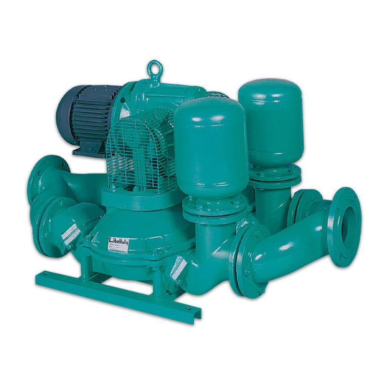
The horizontal self-prime engine-driven centrifugal pump TRASHLIB is basically a pump driven
by a petrol engine, featuring an open vane impeller to allow it to handle even liquids containing
solids. This pump can also operate satisfactorily with liquids containing dissolved gases or air. It
is suitable for handling liquids of viscosity up to 50 cSt, containing solids in suspension, and can
be used in industry, civil engineering, shipbuilding, wastewater treatment, construction and
agriculture. It must not be used in a potentially explosive atmosphere. Always quote the pump
type printed on the relevant nameplate, or the serial number, when ordering/making enquiries etc.

1.2 Construction
Main pump elements:
1 – Discharge port, 2 – Suction port, 3 – Moving handle, 4 – Drainage plug, 5 – Engine, 6 –
Tyre, 7 – pump casing, 8 – Muffler, 9 – Frame, 10 – Air filter, 11 – fuel tank, 12 – pump
filling plug.

2
Specification and dimensions
Trashlib 2
Max capacity
51m3/h
Max head
30m
Solids handling
28mm
Weight
38kg
Connection ports
2” DN50
Dimensions LxWxH
730x700x750
Petrol engine
Honda
Displacement
163 cm3
Starting
Pull start
Power
3,6 kW
Nominal speed
3600 rpm
Fuel tank capacity
3,1 L
Cooling
Air

3
Performance and curve

4
Safety instruction
This manual contains warning and safety symbols. Do not ignore the instructions. They
are provided for the benefit of your health and safety and to prevent damage to the
environment and the pump unit.
DANGER
When the danger symbol with the text DANGER is shown, it is accompanied by
information that is of great importance for the safety of everyoneconcerned.
Ignoring the information can result in injury (possibly severe) or evendeath.
WARNING
When the warning symbol with the text WARNING is shown, it is accompanied by
information that is of great importance for everyone concerned with the pump unit.
Ignoring the information can result in injury or damage (possibly severe) to the pump
unit.
The pump unit conforms to the European Machinery Directive. However, this does not
exclude the possibility of accidents if used incorrectly.
Use of the pump for an application and/or deployment of the pump in an environment
other than defined at the time of purchase is strictly prohibited and can result in a
hazardoussituation.
This is particularly true for corrosive, toxic or other hazardous liquids. The pump unit
may only be installed, operated and maintained by persons who have received
appropriate training and are aware of the associated dangers.
The installer, operator and maintenance personnel must comply with the local safety
regulations. The company management is responsible for ensuring that all work is
performed by qualified personnel in a safe manner. It is not permitted to make changes
to the pump unit without written permission from Caffini pump.
Ensure that hot/cold and rotating parts of the pump are shielded adequately to
prevent unintentional contact.
It is not permitted to start the pump if such guards are missing or damaged.
The company management must ensure that everyone who works with/on the pump unit
is aware of the type of liquid that is being pumped. These persons must know what
measures are to be taken in the event of leakage.
Dispose of any liquids that have leaked, in a responsible manner. Observe local regulations.
Never allow the pump unit to run with a blocked discharge line. The heat build-up could lead
to an explosion
WARNING
Only appropriate fire extinguishers (e.g. carbon dioxide) are to be used in case of fire
or any other situation where open flames appear inside or outside the equipment. It is
strictly prohibited to use water to put out the flames
Do not
1. Do not carry out maintenance operations during functioning.
2. Do not run the petrol or diesel engine inside a closed environment. The exhaust gases
contain carbon monoxide, an odorless and deadly poison.
3. Do not near hands or feet to the moving or rotating parts.

4. Do not hold, pour or use combustibles in presence of naked flame, and of devices like
stoves, boilers or appliances able to generate sparks.
5. Do not refill fuel in closed and scarcely ventilated environments.
6. Do not refuel during functioning. Leave the engine to cool before refueling. Keep the
combustibles in appropriate containers, safety Standards approved.
7. Do not remove the fuel tank plug while the engine is running.
8. Do not run the engine if you smell petrol or there is some other risk of explosion.
9. Do not activate the motor if fuel leaks. Do not transport the engine with petrol in the tank.
10. Do not check ignition with the spark plugs or cable of the spark plug disconnected: use
an appropriate tester.
11. Do not run the engine with the spark plug dismantled.
12. Do not hit the flywheel with sharp or metal objects as this can cause the breaking and
disconnection of metal parts during movement.
13. Do not touch silencers, cylinders or cooling fins when hot, as contact can cause burns.
14. To avoid certain parts hitting persons in case of machine falling, ensure that during the
lifting operations, no persons are within the action range of the machines for lifting. The
lifting, transport and placing operations must be carried out by qualified technical staff
and trained in the specific intervention fields.
15. Before every handling, always ensure the lifting mean with relative tools (ropes, hooks,
etc...) are suitable for lifting the load to be handled and check the required stability of the
latter
Suspended loads danger
It is forbidden to stand under the loads
It is forbidden to remove safety protections
ATTENTION, do not open with the engine running

5
Transportation and lifting
The machine can only be handled with the suction and delivery piping disconnected and with the
power supply motor still or disconnected. The machines installed on frame can be handled with
lifting appliances that can be connected to the lifting hook envisioned on the same machine, using
suitable safety systems.
The machine must be transported in horizontal position and in optimal safety conditions. Lift the
unit using only the lifting points. Before handling the machine, check dimensions and weights on
the plate. Do not stand within the action range during handling of the machine. During the start-‐
up and maintenance interventions, envision a safe transport of all components using appropriate
harness. Handling must be carried out by specialised staff to avoid damaging the machine and
causing accidents to staff. The lifting points of the various components must only be used to lift
the components for which they were supplied. Do not stand or transit underneath and near-‐by
the machine when it is lifted from the ground. To anchor the machine to the transport surface,
block the same using ropes or chains.
N.B. No additional accessory can be connected to the motor pump or electric pump unit
during the lifting or the handling.

6
Pipework and installation
6.1 Pipework
Clean pipework thoroughly before connecting it to the pump. Suction pipes must have the same
diameter as the pump’s suction port. Where possible, avoid curves, elbows or constrictions liable
to limit the flow of liquid to the pump.
Install the pump as near to the liquid to be pumped as possible. Where possible, try to reduce the
length of the suction pipe.
Suction pipe connections must be completely airtight: check pipe threads, flange gaskets, quick
couplings etc.
Beware of water hammering
WARNING
Do not allow any vehicle to run over the delivery hose.
Do not close the delivery valve abruptly because water
-hammer may occur.
This may result in heavy damage to the pump.

7
Preparation for starting
WARNING
If the pump is equipped with a vacuum pump, the pump does not have to be filled
with the pumped liquid.
DANGER
Before operating the pump, check that all parts of the system have been correctly installed
and that all safety devices are operative.
7.1 CHECKING THE SEAL
Before starting the pump, check the type of mechanical seal shown on the pump name plate.
To grease every 300 hours of work the pump’s mechanical seal.
7.2 Filling the pump casing
Fill the pump casing completely with the liquid to be pumped through the opening on the top of
the casing (1). When the pump is stopped, the casing does not empty and therefore it is not
necessary to refill it.
7.3 Check fuel in fuel tank
WARNING
Always check fuel level in fuel tank. Don’t start the pump when fuel is running low. In
this case air can get in fuel system.

WARNING
Filling up the fuel, engine MUST be switched off.
7.4 Check oil level in engine
WARNING
Hot oil and components can cause personal injury. Do not allow hot oil or hot
components to contact the skin.
Note
Perform this maintenance engine must be stopped
1. Remove engine level dipstick (1) level must be above MIN level mark
2. If necessary to fill some oil, fill it through oil dipstick hole(1) .
7.5 Checking safety and environmental risks
THE FOLLOWING ACTIONS ARE STRICTLY FORBIDDEN:
•Using the pumps in a potentially explosive atmosphere.
•Carrying out maintenance with the engine running.
•Climbing on top of the engine-driven pump to perform work of any kind.
•Working on the pump when it is connected to an active remote control.
•Before starting the trailer-mounted pump, make sure the wheels are suitably
locked.
•Do not use the engine-driven pump indoors.

7.6 Checking visual inspection
•Check pump of any leakage
•Check of any cracks
•Check if not missing or damaged parts
•Suction and discharge ports are not damaged
•etc
7.7 Priming
Attention: if the pump does not prime, do not operate it for more than 2 minutes to avoid
overheating the liquid and damaging the seal. If the pump does not prime, read paragraph
Engine driven pumps should be brought up gradually to running speed. Never change the
accelerator limit stop: at speeds higher than that for which the engine is set, the pump would
absorb more power than the engine can supply.
Never exceed the maximum speed shown on the pump name plate.
When the pump has primed:
1. Check the shaft seal for leaks.
2. Check that the current absorbed by the motor does not exceed the rated value shown on
the name plate.
3. If the pump does not seem to be operating normally, it must be stopped and the cause
found in troubleshooting section.

8
Starting
1.
Check the pump type (type plate) and the characteristics of the pump unit, such as: rpm,
operating pressure, power consumption, operating temperature, direction of rotation, NPSH,
etc.
2.
Check whether the pump unit is placed in accordance with the instructions. Pay particular
attention to the area around the pump unit. Make sure the pump unit can draw adequate
freshair.
3.
Check whether the prescribed safety provisions are in place.
4.
Connect the hoses
5.
Perform preparation for starting
6.
Turn the engine start-Stop switch to position “ON” (1)
7.
Open fuel lever (2)
8.
If engine is cold, close choke lever (3)
9.
Pull starter handle (4).

10.
When motor is started open choke lever (3). Engine pick up nominal speed and start running
smoothly.
WARNING
If vibration occurs during starting, stop the pump immediately and eliminate the
cause before starting again.
WARNING
.
If the pump vacuum lift is set too high, cavitation in the pump set is
possible and this can
be recognized by High levels of vibration, a crackling
noise in the pump, decreased capacity
and pressure. If this condition is
allowed to persist for long period
s it will cause damage the pump set.
Continued running of the pump set in this condition will invalidate the
warranty
WARNING
Pump not allowed operate without pumping liquid more then 2 minutes. Its can
damage mechanical seal.

9
Stopping
1. Turn the engine start-Stop switch to position “OFF” (1). Observe whether the system comes
to a gradual, smooth stop
2. Close Fuel throttle (2).
3. When you suspect that the liquid is beginning to freeze, drain the pump while the medium is
still in the liquid state

10
Draining the pump when there is danger of freezing
WARNING
If there is a danger of freezing, a pump used to pump a liquid that may freeze must be
drained (while at a standstill).
1.
Turn off the engine and open draining port (1).
2.
Close drainage port (1), after complete water drainage.

11
Troubleshooting
WARNING
In the event of a malfunction or abnormal operation, shut off the pump or
pump unit immediately to prevent a dangerous situation and/or damage
(possibly severe) to the pump or pump unit.
Inform to responsible persons. Determine the cause of the malfunction.
Resolve the problem before restarting the pump
Problem
Possible cause
Verifications and solutions
Pump does not prime
Delivery pipe under pressure
Bleed delivery pipe.
Impeller may be worn or broken
Disassemble pump casing and check
impeller for wear
Suction strainer, where applicable,
may be clogged
Remove obstructions
Excessive suction lift
Reduce suction lift
Air entering through seal
Disassemble seal and clean it
Impeller clogged by foreign matter
Disassemble casing and remove
foreign matter
Pump does not deliver
liquid
Head required by the system is
greater than the rated head of the
pump
Revise system design or select a
different pump
Excessive flow resistance along
suction line
Revise distribution of elbows, valves,
constrictions etc.; where necessary,
increase diameter of pipework
Impeller clogged by foreign matter
Disassemble casing and remove
foreign matter
Suction/delivery pipes may be
obstructed or clogged
Locate the obstructed or clogged
area and clean
Pump does not deliver
enough liquid
Air leaks in suction line.
Check joints are airtight and inspect
suction pipe.
Impeller and/or wear plate may be
worn.
Replace them by disassembling the
pump
Diameter of the suction pipe too
small
Replace suction pipe.
Pump does not
provide enough
pressure
Viscosity of the liquid is higher than
expected
Contact the pump manufacturer once
you have measured the viscosity of
the liquid.
Viscosity for centrifugal pumps
should not exceed 50 cSt
Pump absorbs too
much power
Pump operates under conditions
that are different from those
specified in the contract
Check operating conditions of pump
and compare them to those on the
pump’s nameplate
Density of the liquid is higher than
planned
Measure density of the liquid and
compare it with the agreed value
Incorrect unit alignment
Check unit is correctly aligned
There may be friction inside the
pump between rotating and non-
rotating components
Disassemble pump casing and check
for scratches on surfaces
Table of contents
Other Caffini Water Pump manuals
Popular Water Pump manuals by other brands

Waterite
Waterite VELO-FLO Installation and owner's manual

Harbor Freight Tools
Harbor Freight Tools DRUMMOND 63323 Owner's manual & safety instructions

Süd Solar
Süd Solar GENUA 01128 instruction manual

Grundfos
Grundfos CMBE 1-44 Installation and operating instructions

Nakayama
Nakayama PRO NP2035 manual

ARO
ARO TWO-BALL NM2202B-X Operator's manual